
Related Manuals for TASKING INFINEON TC377TE


Summary of Contents for TASKING INFINEON TC377TE
- Page 1 INFINEON TC377TE COMPACT EMULATION ADAPTER HARDWARE USER MANUAL V1.5, September 2024 www.tasking.com...
- Page 2 Use included power cord and power supply The enclosed power supply has been approved for use by TASKING. Please contact TASKING if you need to consider an alternative power.
-
Page 3: Table Of Contents
Contents Introduction ......................4 Options ....................... 5 Operation ......................6 Mechanical information ..................7 BGA Assembly ....................9 Accessories ....................10 User Notes ...................... 11 www.tasking.com... -
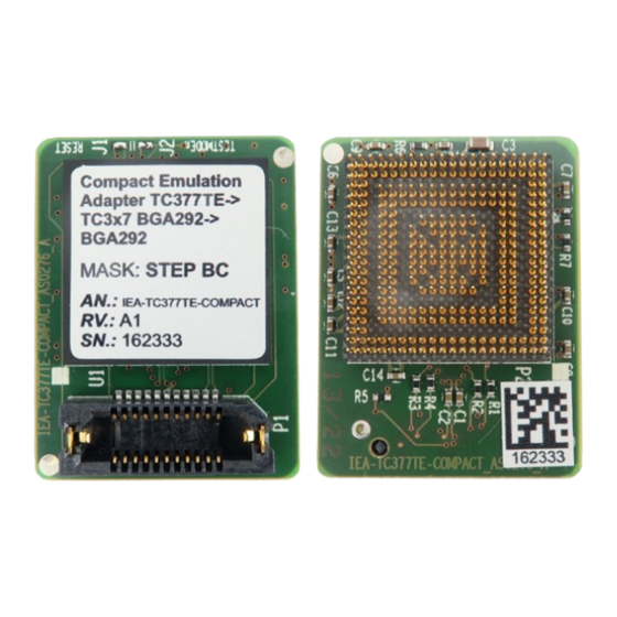
Page 4: Introduction
Introduction Infineon TC377TE Compact Emulation Adapter is custom designed to achieve a minimum vertical size of the BGA292 adaptation. It provides full trace capabilities for: · TC327LP · TC337LP · TC367DP · TC377TP (BGA) microcontrollers where the trace port is not available or lacks the full trace capability. -
Page 5: Options
Solder part, which is being soldered on the embedded target side. The available Solder part and the Extender are listed in the table below. Extender (optional) Solder part Package (Pitch) Type (Ordering code) (Ordering code) TC327, TC337, TC367, BGA292 IA292LFBGA-EXTENDER IA292LFBGA-SOLDER TC377 BGA adaptation Extender (optional) Solder part www.tasking.com... -
Page 6: Operation
Signal Direction is described from the BlueBox perspective. Blue color marks the trace signals. Be aware that debug and trace signals from the Emulation Adapter superset device are not connected to the target board. They are exposed only to the connectors on the Emulation adapter. www.tasking.com... -
Page 7: Mechanical Information
Side view of the Emulation Adapter, one Extender and Solder part (each Extender adds approx. 3,25mm) Unit (mm) Ordering code IEA-TC397XE Compact 29.1 22.4 Extender Side view of the Extender Top view of the Extender Unit (mm) Ordering code IA292LFBGA-EXTENDER 3.25 www.tasking.com... - Page 8 Solder part Side view of the Solder part Top view of the Solder part Unit (mm) Ordering code IA292LFBGA-SOLDER 3.12 To view Emulation Adapter schematics, use the short link isystem.com/schematics. www.tasking.com...
-
Page 9: Bga Assembly
Emulation Adapter. Keep the number of Extenders C at minimum since every Extender degrades the signal integrity of the electrical signals. 3. Connect the Emulation Adapter D to: · Solder part B or · Extender C BGA Adaptation setup www.tasking.com... -
Page 10: Accessories
Ordering Code Description IC70003 iC7max BlueBox IC57000 iC5700 BlueBox IC57031 iC5700 Hub (3 x FNet & FBridge) IC57040 CAN/LIN IC57041 ADIO Active Probes Ordering code Description IC71164 / IC57164 Infineon AGBT Active Probe More information about our products via sales@tasking.com. www.tasking.com... -
Page 11: User Notes
User Notes This page is intentionally left blank. www.tasking.com... - Page 12 Visit our website for: · Support - support.tasking.com · Getting started - isystem.com/start · Knowledge Base - kb.tasking.com www.tasking.com www.tasking.com...
Need help?
Do you have a question about the INFINEON TC377TE and is the answer not in the manual?
Questions and answers