
Related Manuals for TASKING iSystem Cypress CYT2B9


Summary of Contents for TASKING iSystem Cypress CYT2B9
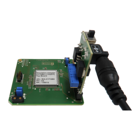
- Page 1 Cypress CYT2B9 Emulation Adapter Hardware User Manual V2.6, November 2023 isystem.com/start...
- Page 2 General safety instructions Please read the following safety precautions carefully before putting this device to use to avoid any personal injuries, damage to the instrument, or to the target system. Use this instrument only for its intended purpose as specified by this manual to prevent potential hazards. Use included power cord and power supply The enclosed power supply has been approved for use by iSYSTEM.
-
Page 3: Table Of Contents
Contents Introduction ............................4 Package content ..........................5 Adaptation packages content ......................6 Operation ............................... 8 Adaptation setups ........................... 9 Screws ..............................................11 Configuration ............................12 Connectors .............................. 16 Power supply package ......................... 17 Standalone operation ........................... 18 Mechanical information ......................19 Accessories ............................ -
Page 4: Introduction
Introduction Cypress CYT2B9 Emulation Adapter is based on the 176-pin CYT2B98CA superset device and provides full trace capabilities for the · 64-pin · 80-pin · 100-pin · 144-pin Traveo II CYT2B9 Adaptation, where trace port is not available or lacks the full trace capability. The Emulation Adapter might differ in some peripherals from the target device;... -
Page 5: Package Content
Package content Cypress CYT2B9 Emulation Adapter is delivered with all components required for Standalone operation. Adaptation package for the Target board and the Power adapter must be ordered separately. Power supply package Cypress CYT2B9 Emulation Adapter Power converter Power adapter Ordering code: Ordering code: Ordering code:... -
Page 6: Adaptation Packages Content
Adaptation packages content Target Adaptation Conversion boards connect between the Emulation Adapter and the matching Solder part which is being soldered on the Target side. Pin number Conversion board Type Solder part IEA-CYT2B9-ATQ64 Fixed IA64ATQ-SOLDER IEA-CYT2B9-ATQ64W Flex IA64ATQ-SOLDER IEA-CYT2B9-ATQ80 Fixed IA80ATQ-SOLDER IEA-CYT2B9-ATQ80W Flex... - Page 7 Measurement board The Measurement board connects between the Emulation Adapter and the Conversion board. Embedded targets often do not have access to all the MCU pins / connected signals to connect with measurement equipment (oscilloscope, logic analyzer), its use provides easy access to all MCU pins.
-
Page 8: Operation
Operation Emulation Adapter offers the following setups: · Fixed Adaptation · Flex Adaptation(with Wire adapter) Top/bottom side of the Emulation Adapter Introduction to Emulation Adapter (video) How to connect Hardware (video) isystem.com/ea-intro isystem.com/connect-hardware... -
Page 9: Adaptation Setups
Adaptation setups Fixed Adaptation... - Page 10 Flex Adaptation...
-
Page 11: Screws
Screws Slot screw The Slot screw (30mm) is used to fix the Conversion board to the Solder part. The setup be- comes mechanically more robust.Screw the Conversion board to the Solder part first, before the Emulation Adapter is attached on top and watch out not to break out the Solder part, e.g., if you accidentally hit the Emulation Adapter from the side. -
Page 12: Configuration
Configuration J1: Target reset configuration Jumper J1 connects the Emulation Adapter reset line and the user target board reset line and is populated by default. EA also features a Reset push button (SW1). If having problems establishing the initial debug session with the Emulation Adapter, remove J1 and try again. - Page 13 J4 - J13: Trace port configuration Soldered jumpers are by default placed to connect ARM CoreSight 20 connector trace signals to port P18 (J9 – J13). If P18 on user target board is used for any other purpose than trace, Emulation Adapter allows changing the trace source to port P22 (J4 –...
- Page 14 winIDEA configuration By default, P18 port pins (P18_3 – P18_7) or P22 port pins (P22_0 – P22_4) are set as GPIO pins. To configure these pins as trace pins in winIDEA, open Hardware menu / CPU Options / Analyzer tab and add a script in the SoC Initialization section.
- Page 15 P2: Power supply configuration Emulation Adapter Power supply is configured via the unshrouded 26-pin 2.54 mm header (P2). Signal direction Signal Signal Signal direction Target board VDDA CVDDA Emulation device Target board VREFH CVREFH Emulation device Not Connected Not Connected Target board VDDIO_1 CVDDIO_1...
-
Page 16: Connectors
Connectors P1: CoreSight 20 connector CoreSight 20 connector P1 exposes debug and trace signals and has the following pinout on the Emulation Adapter side: Signal Signal CVDDA TMS_SWDIO TCK_SWDCLK TDO_SWO RESETn TRACECLK TRACEDATA[0] TRACEDATA[1] TRACEDATA[2] TRACEDATA[3] Debug and Trace CoreSight 20 connector pinout Signal Direction is described from the BlueBox perspective. -
Page 17: Power Supply Package
Power supply package A Power supply package, which is delivered with the Emulation Adapter, is required when: · The Emulation Adapter is used as a standalone device . · The target board doesn’t provide an accurate supply voltage. · The target board doesn’t provide sufficient current for the Emulation Adapter operation. The Power converter can supply either 3.3 V or 5 V. -
Page 18: Standalone Operation
Standalone operation Emulation Adapter is delivered with all components required for a Standalone operation. Power supply Use enclosed IEA-PS Emulation Adapter Power converter and adapter. Clock source If user target’s crystal circuit microcontroller oscillator (if available) is not an adequate clock source, insert appropriate crystal into the Q1 socket, replace the default 10pF C24 and C25 ca- pacitors when necessary and place jumpers J2 and J3 in 2-3 position. -
Page 19: Mechanical Information
Mechanical information Solder part solder pad view Top view of the Solder part Side view of the Solder part Side view of the Emulation adapter complete setup - QFP Fixed Adaptation Top view of the Emulation Adapter Top view of the Conversion board... - Page 20 Solder parts In the case of soldering the Solder part manually, it’s highly recommended to prolong the solder pad E on the outer side (e.g., for 1.5–2 mm) during the PCB design. Note that without this modi- fication, it’s very difficult to solder the Solder part manually. Recommended PCB footprint dimensions: Unit (mm) IA64ATQ-SOLDER...
-
Page 21: Accessories
Accessories Ordering Code Description IC5700 iC5700 BlueBox IC5000 iC5000 BlueBox IC57031 IOM6 Hub (3 x FNet & FBridge) IC57040 IOM6 CAN/LIN IC57041 IOM6 ADIO Debug Adapters Listed Debug Adapters provide tracing functionality. Ordering Code Description IC50118-2 20-pin 1.27 mm CoreSight Debug Adapter IC50118-LV 20-pin 1.27 mm Low Voltage CoreSight Debug Adapter More information about our products on... -
Page 22: User Notes
User Notes This page is intentionally left blank. - Page 23 Visit our website for: · Support - isystem.com/support · Tutorials - isystem.com/start · Knowledge Base - kb.isystem.com www.isystem.com...
Need help?
Do you have a question about the iSystem Cypress CYT2B9 and is the answer not in the manual?
Questions and answers