Table of Contents
Advertisement
Quick Links
INSTALLATION AND OPERATION INSTRUCTIONS
OWNER / INSTALLER: For your safety this manual must be carefully and thoroughly read and understood before
installing, operating or servicing this heater. This heater is intended for use with either Natural Gas or Propane
Gas. It must be installed by a qualified service person or a licensed contractor in accordance with National and
local codes.
▲WARNING: Improper installation, adjustment, alteration, service, or maintenance can cause property damage,
injury or death. Read the installation, operation and maintenance instructions thoroughly before installing or
servicing this equipment. For assistance or additional information, consult a qualified installer, service agency or
the gas supplier.
INSPECT all combustion air openings into the building and, if necessary, clear if they become blocked by dust.
FOR YOUR SAFETY: If the heater is installed without a flue, exhaust fans MUST be operating on an appropriate
cycle when heaters are operating to avoid a high concentration of carbon monoxide. When used without fresh
air, this heater may give off carbon monoxide, an odorless and poisonous gas. CARBON MONOXIDE POISONING
MAY LEAD TO DEATH. Early signs of carbon monoxide poisoning resemble the flue with headaches, dizziness and
nausea. If you experience these signs, GET FRESH AIR IMMEDIATELY! Have the heaters serviced as soon as
possible and check the ventilation in the house.
These heaters are designed for non residential space heating applications and may operate with the use of
either Natural Gas or Liquid Propane (LP) Gas. Check the heater's nameplate to determine the correct gas type
before proceeding with installation.
!INSTALLER: This manual is the property of the owner. Please present this manual to the owner when you leave
the job site.
IF YOU SMELL GAS:
! DO NOT try to light any appliance.
! DO NOT touch any electrical switch; DO NOT use any
telephone in your building.
! IMMEDIATELY call your gas supplier from a neighbour's
telephone. Follow the gas supplier's instructions. If you
cannot reach your gas supplier, call the fire department.
!IMPORTANT: SAVE THIS MANUAL FOR FUTURE REFERENCE.
Phone 01473 830551 Fax: 01473 832055 E-mail:
OVERHEAD RADIANT TUBE HEATERS
Models: ADU25, ADU30, ADU35, ADU40, ADU45,
ADL25, ADL30, ADL35, ADL40, ADL45
Single Stage Pull Through System (Negative Pressure)
FOR YOUR SAFETY
Gas Fired Products (UK) Ltd.
Chapel Lane, Claydon, Ipswich, Suffolk IP6 0JL, England
DO NOT store or use petrol or other flammable
vapors and liquids in the vicinity of this or any
other appliance.
info@spaceray.co.uk www.spaceray.com.uk
Form #44201100
Oct 2019
Advertisement
Chapters
Table of Contents

Subscribe to Our Youtube Channel
Related Manuals for Space-Ray ADU25


Summary of Contents for Space-Ray ADU25
- Page 1 INSTALLATION AND OPERATION INSTRUCTIONS OVERHEAD RADIANT TUBE HEATERS Models: ADU25, ADU30, ADU35, ADU40, ADU45, ADL25, ADL30, ADL35, ADL40, ADL45 Single Stage Pull Through System (Negative Pressure) OWNER / INSTALLER: For your safety this manual must be carefully and thoroughly read and understood before installing, operating or servicing this heater.
-
Page 2: Table Of Contents
TABLE OF CONTENTS SECTION DESCRIPTION PAGE 1.0) Safety ..............................2 2.0) Installer Responsibility ........................2 3.0) General Information .......................... 2 4.0) Minimum Clearances to Combustibles................... 4 5.0) Specifications ............................. 5 6.0) Packing List ............................7 7.0) Dimensions – U Tube Configurations .................... 13 7.1) Heater Assembly Overview –... -
Page 3: Safety
Ventilation requirements are addressed further in these instructions. Although these heaters may be used in many applications other than space heating (e.g., process heating), Space-Ray will not recognize the warranty for any use other than space heating. Form #44201100... - Page 4 This heater is not an explosion proof heater. Where the possibility of exposure to volatile and low flash point materials exists, it could result in property damage or death. This heater must not be installed in a spray booth where the heater can operate during the spraying process. Consult your local fire marshal or insurance company. Linear Configuration Series Only: Since linear configuration tube heaters are always hotter at the control end than at the flue terminal end, always observe the minimum recommended mounting heights.
-
Page 5: Minimum Clearances To Combustibles
“specify the maximum permissible stacking height to maintain the required clearances from the heater to combustibles.” Space-Ray recommends posting these signs adjacent to the heater thermostat or other suitable location that will provide enhanced visibility. -
Page 6: Specifications
No. 39 Burner Baffle Plate PN 4260360C Fan Air Restrictor Plate None Electrical Supply 230V~50Hz 125W Fuse Externally Dimensions ADU25: 5.385m x 0.465m ADL25: 10.065m x 0.34m Weight ADU25: 47kg ADL25: 46kg Gas Connection R - ½ Flue Size Ø100mm... - Page 7 Table 5 MODEL ADU40/ADL40-N ADU40/ADL40-L Heat Input 42.2kW Hs 38.0kW Hi Appliance Type (II A2, B 2H3P Appliance Category 2H3P Adjusted for 2H G20 20mbar 3P G31 37mbar Setting Pressure 12.5mbar 25mbar Injector Ø5.0mm Ø3.3mm Burner Baffle Plate PN 4260360T Fan Air Restrictor Plate None Electrical Supply...
-
Page 8: Packing List
6.0) PACKING LIST 6.1 ADU25 The appliances are supplied as follows: Table 7 REF. NO. PART NO. DESCRIPTION ADU25 Carton (containing the following) Fastenings Pack (not shown) Burner Box Assembly 44438010 Fan Assembly – 3” (less air plate) 42764000 U-Bend... - Page 9 ADU30/35 The appliances are supplied as follows: Table 8 REF. NO. PART NO. DESCRIPTION ADU30 ADU35 Carton (containing the following) Fastenings Pack (not shown) Burner Box Assembly 44438020 Fan Assembly – 4” (with air plate) 42913000 U-Bend 42898100 Hanger Bracket 42873000 U-Bolts (included in fastenings pack) 30462980...
- Page 10 ADU40/45 The appliances are supplied as follows: Table 9 REF. NO. PART NO. DESCRIPTION ADU40 ADU45 Carton (containing the following) Fastenings Pack (not shown) Burner Box Assembly 44438510 Fan Assembly – 4” (less air plate) 42913000 U-Bend 42898100 Hanger Bracket 42873000 U-Bolts (included in fastenings pack) 30462980...
-
Page 11: 4A 42873000 U-Bolts (Included In Fastenings Pack)
ADL25 The appliances are supplied as follows: Table 10 REF. NO. PART NO. MODEL ADL25 Carton (containing the following) Fastenings Pack (not shown) Burner Box Assembly 44438010 Fan Assembly – 3” (less air plate) 43318100 Hanger Brackets 42770000 U-Bolts (included in fastenings pack) 30462990 Torctite Coupling 42766000... - Page 12 ADL30/35 The appliances are supplied as follows: Table 11 REF. NO. PART NO. MODEL ADL30 ADL35 Carton (containing the following) Fastenings Pack (not shown) Burner Box Assembly 44438020 Fan Assembly – 4” (with air plate) 44438030 Fan Assembly – 4” (less air plate) 43318100 Hanger Bracket 42873000...
- Page 13 ADL40/45 The appliances are supplied as follows: Table 12 REF. NO. PART NO. MODEL ADL40 ADL45 Carton (containing the following) Fastenings Pack (not shown) Burner Box Assembly 44438510 Fan Assembly – 4” (less air plate) 43318100 Hanger Bracket 42873000 U-Bolts (included in fastenings pack) 30462980 Torctite Coupling 41932100...
-
Page 14: Dimensions - U Tube Configurations
7.0) DIMENSIONS – U TUBE CONFIGURATIONS Fig. 9 Fig. 10 Form #4420110 Oct 2019 -13-... - Page 15 Fig. 11 Form #44201100 -14- Oct 2019...
-
Page 16: Heater Assembly Overview - U Tube Configurations
7.1) HEATER ASSEMBLY OVERVIEW – U TUBE CONFIGURATIONS Fig. 12 Form #4420110 Oct 2019 -15-... - Page 17 Fig. 13 Form #44201100 -16- Oct 2019...
- Page 18 Fig. 14 Form #4420110 Oct 2019 -17-...
-
Page 19: Dimensions - Linear Tube Configurations
8.0) DIMENSIONS – LINEAR TUBE CONFIGURATIONS Fig. 15 Form #44201100 -18- Oct 2019... -
Page 20: Heater Assembly Overview - Linear Tube Configurations
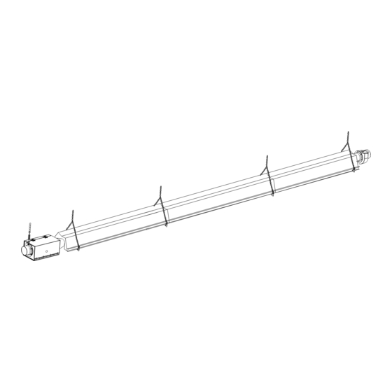
8.1) HEATER ASSEMBLY OVERVIEW - LINEAR TUBE CONFIGURATIONS The heater lengths for each input are shown in Section 5.0). Insure that all reflector screws and clips are in place to prevent the reflectors from separating during expansion and contraction of the heater. The heater should be suspended to provide a slope of 0.25 degree up to the fan. - Page 21 Fig. 17 Form #44201100 -20- Oct 2019...
- Page 22 Fig. 18 Form #4420110 Oct 2019 -21-...
-
Page 23: Typical Suspension Methods
The appliance should be located with respect to building construction and other equipment to permit access to the appliance for servicing etc. Space-Ray recommends that the body sections be suspended using chains with turnbuckles. This will allow slight adjustments after assembly and heater expansion/ contraction during operation. -
Page 24: Burner Box Support Details
9.1) BURNER BOX SUPPORT DETAILS The Burner Box must be supported with a welded chain after overall heater suspension is complete. This is to prevent burner from sagging. Assemble bracket and turnbuckle to inlet end of burner as shown. Fig. 20 Adjust the turnbuckle until control box is level. -
Page 25: U-Tube Heater Assembly
3. Space the hanger brackets according to the dimensions shown in the figures below for the first tube section. Note: The distances are measured from center of the holes of each support/hanger bracket. See figure 21 below for ADU25 and Figure 21a for ADU30/35/40/45. (Note for ADU25 install all three hanger brackets). Fig. 21... - Page 26 Fig. 21a I. Place tubes over the hanger brackets with the welded seam facing down toward the ground. Failure to assemble the tube with the seam facing down will void the manufacturer’s warranty. II. Secure the tubes to each support/hanger bracket using U-bolt clamps and 5/16-18 nuts provided. See Details A or B of Fig.
- Page 27 Fig. 21c Fig. 21d 6. For models ADU 40/45 suspend the hanger bracket for the second section of tube, raise the tubes into position and join the tube sections together using Torctite couplings as described in Section 10.2 “Tube Coupling Details”. Fasten the tubes onto the hanger bracket. See figure 21e, f and g below for installation sequence.
- Page 28 Fig. 21f Fig. 21g 7. Insert turbulators (where required) into the tube sections as described below. Form #4420110 Oct 2019 -27-...
- Page 29 I. Assemble the turbulators together by interlocking the slotted ends. II. Slide these into the tubes at the U-bend as shown for U-Models. III. Align the turbulator end flush with end of tube. Note: Refer to the table below for the number of turbulators required for each heater model. Table 13.
- Page 30 Dimension First Reflector First reflector Second Second Third from first length overlap Reflector reflector Reflector hanger to end Length overlap Length of reflector ADU25 76mm 2438mm 116mm 2438mm ADU30/35 214mm 3035mm 396mm 2540mm ADU40/45 214mm 3035mm 182mm 2540mm 182mm 1511mm Fig.
- Page 31 Fig. 21k 11. Attach the reflector spacer brackets at each tube support/hanger bracket. using the #10-24 machine screws supplied in fastening kit. See figure 21l below: Fig. 21l 12. Place the upper reflector panels over each of the reflector spacer brackets. Repeat the same reflector positions and overlap dimensions as specified in table 14, see step 9 above.
- Page 32 13. Secure the upper reflector panels to the reflector spacer brackets as shown in figure 21n below: I. Screw through the reflector with the #10 self drilling screws into the reflector spacer bracket. II. Repeat this at each hanger bracket specified in figure 21n. Fig.
-
Page 33: Linear Heater Assembly
15. Attach burner box and fan assembly as shown in Sections 10.3 and 10.4. 16. Tighten all screws securing clamps and brackets installed earlier. Place end reflector caps and secure using screws (supplied in fastening kits) as shown in Fig 21p below: Fig. - Page 34 III. Place tubes over the hanger brackets with the welded seam facing down toward the ground. Failure to assemble the tube with the seam facing down will void the manufacturer’s warranty. IV. Secure the tubes to each support/hanger bracket using U-bolt clamps and 5/16-18 nuts provided. See Fig.
- Page 35 6. Insert turbulators (where required) into the tube sections as described below. IV. Assemble the turbulators together by interlocking the slotted ends. V. Slide these into the tubes at the end of the heater as shown for Linear Models. VI. Align the turbulator end flush with end of tube. Note: Refer to the table below for the number of turbulators required for each heater model.
- Page 36 Table 16. Model ADL25 3035 3035 3035 ADL30/35 3035 3035 3035 ADL40/45 3035 3035 3035 3035 All Dimensions in mm. Fig. 22e 8. With the lower reflector panels in place secure the reflectors to the hanger brackets on both sides of the reflector as shown in figure 21f.
- Page 37 Fig. 22g 10. Place the upper reflector panels over each of the reflector spacer brackets. Repeat the same reflector positions and overlap dimensions as specified in table 16, see step 9 above. To align reflectors precisely to the ends of the lower reflector, hold the end cap in place against the lower reflector slide the upper reflector to rest against it.
-
Page 38: Tube Coupling Details
12. Place side panels over the sides of both reflector panels between each tube support/hanger bracket and at the ends of the heater. Secure these in place using the side panel holder brackets and two #10 x 1/2” sheet metal screws supplied in fastenings kit. See Figure. 22j below: Fig. - Page 39 Place the compression coupling over the end of the tube. Use the small hole at the centerline of the coupling to check that the coupling is inserted correctly. Partially tighten the bolt nearest the end of the tube (approximately half closed). Fig.
-
Page 40: Attaching Burner Box Assembly
10.3) ATTACHING BURNER BOX ASSEMBLY Fig. 24 1. Place a Torctite Coupling over the end of the Radiant Tube (refer to Section 10.2 “Tube Coupling Details”). Assemble the Burner Box to the Radiant Tube ensuring that it engages fully into the Torctite Coupling and is positioned vertically. -
Page 41: Gas Connections And Regulations
11.0) GAS CONNECTIONS AND REGULATIONS IMPORTANT BEFORE CONNECTING THE GAS TO THE HEATER Connect to the supply tank or manifold in accordance with state or local building codes. Authorities having jurisdiction should be consulted before the installation is made. Check that the gas fuel on the burner rating plate matches the fuel for the application. Check that the gas supply piping has the capacity for the total gas consumption of the heaters and any other equipment connected to the line. - Page 42 Fig. 26 Fig. 27 Fig. 28 Radiant tube heaters will expand and contract during operation. Therefore it is essential to provide a flexible metallic hose, which must conform, to national or Local Regulations, to connect the appliance to the gas supply. Minimum size to be ½" (12.7mm) bore. The gas pipe, flexible hose and connections must be self supporting.
-
Page 43: Instructions For Pressure Test Gauge Connection
11.1) INSTRUCTIONS FOR PRESSURE TEST GAUGE CONNECTION CHECKING GAS PRESSURES Switch off the gas and electricity and gas supply to the appliance. NOTE: Turn off manual shutoff at gas line otherwise gas comes out. Connect a manometer to the test nipple protruding from the rear panel of the Control Box (adjacent to the Air Inlet Adaptor). - Page 44 2. After testing pressure and adjusting the regulator, turn off all electrical power to the system, remove manometer tubes, turn OUTLET test screw clockwise to seal pressure port. Tighten to 1.0 Nm torque minimum. Turn on system power. Fig. 29a Fig.
-
Page 45: Electrical Connections
12.0) ELECTRICAL CONNECTIONS The electrical wiring to this heater must be installed in accordance with the latest or current National Regulations and any Local Regulations, which apply. Electrical supply 230V~50Hz 125W Current rating 0.55 Fuse externally 1. Using a suitable cable connector and twin core and earth PVC covered flexible supply cable, (0.5 mm National or Local standard specification) connect the fan leads to the 3 pin plug provided (fastenings pack) as follows:- Brown (red) - Page 46 Multiple Heaters per Thermostat connection diagram Fig. 32 Notes: The method of connection to the electrical supply must facilitate complete isolation and should preferably be via a fused double pole isolator having a constant separation of at least 3mm in all poles and supplying the appliance ONLY.
-
Page 47: Venting And Fresh Air For Combustion
13.0) VENTING AND FRESH AIR FOR COMBUSTION These appliances may be installed with an exhaust flue fitted or without an exhaust flue fitted. A. FLUELESS (UNFLUED) The installation room should have a volume of at least 10m/m kw of installed nominal heat input of the radiant heater. - Page 48 AIR SUPPLY Air supply openings are required to admit air and shall be located below the radiant heaters. The total area of the unobstructed cross-sections of all the air supply openings shall not be smaller than the total area of the unobstructed cross-sections of all the exhaust openings. Slits and gaps of fixed cross-section can also be used as air supply openings.
- Page 49 Fig. 34 16.1 Type A Outside (ducted) combustion air supply. When installed in a dusty or polluted atmosphere, the heater should be fitted with a ducted supply of clean fresh air. A length of 100mm flexible ducting should be installed between the Control Box Air Inlet and any rigid ducting and be secured to the Air Inlet with hose clips.
- Page 50 Fig. 35 Form #4420110 Oct 2019 -49-...
- Page 51 16.4 TypeC The following figure shows the typical arrangements for concentric vertical flues, see Table 18 for 90° bend equivalent lengths. The bends shown in the illustrations connecting the combustion air intake to the concentric ducts is calculated into the overall length. For example a system with one additional 150/100mm Ø...
-
Page 52: Heater Operation
Type C fresh air connector 16.6 The connectors for the Type C fresh air are supplied as an accessory. The installation steps for the Type C connector are shown in figure 38a below. Fig. 36a 14.0) HEATER OPERATION Form #4420110 Oct 2019 -51-... -
Page 53: Sequence Of Operation
14.1) SEQUENCE OF OPERATION The chart below shows the sequence of operation for the normal operating cycle. Fig. 37 If the flame is not sensed during sequence T3 then the heater will go to lockout. It is essential that all new pipework installations are purged and tested for soundness with a suitable leak detection fluid prior to attempting to ignite any appliance. -
Page 54: Cleaning And Annual Maintenance
15.0) CLEANING AND ANNUAL MAINTENANCE This heater must be cleaned and serviced annually by a qualified contractor before the start of each heating season and at any time excessive accumulation of dust and dirt is observed. Maximum heating efficiency and clean combustion will be maintained by keeping the heater clean. - Page 55 Main Burner and Orifice: Check the Main burner and orifice; remove any dirt or debris including spider webs. See Sections 18.2 and 18.3 . Electrical Wiring: Check that all the electrical connections are sound and that the wiring is undamaged. Replace damaged wires as necessary.
-
Page 56: Troubleshooting Guide
17.0) TROUBLESHOOTING GUIDE Form #4420110 Oct 2019 -55-... - Page 57 Form #44201100 -56- Oct 2019...
-
Page 58: Replacing Parts
18.0) REPLACING PARTS Only use genuine Space-Ray replacement parts. Parts are available from the factory for replacement by a licensed person. Refer to the Replacement Parts Guide in Section 21.0 for all replacement parts. IMPORTANT: Disconnect gas and electricity supplies to the appliance before carrying out any repair work. This work can be carried out at high level using a purposes designed access tower, but it is preferable that this work should be carried out at ground level. -
Page 59: Removing Main Burner
18.2) REMOVING MAIN BURNER Fig. 39 1. Unscrew the two M4 x 25 setscrews from the Burner Bracket and remove the Burner Clamp. 2. Unscrew the Burner from the Injector Fitting 3. Lift the burner out of the Control Box. 4. -
Page 60: Removing Ignition Control
18.4) REMOVING IGNITION CONTROL Fig. 41 1. Remove the screws securing the cover panel to the Ignition Control Module. 2. Disconnect the 12 way Molex electrical connector and the white HT ignition spark/flame sensor lead from the Ignition Control. 3. Slide out the Ignition Control. 18.5) REMOVING AIR SWITCH Fig. -
Page 61: Removing Gas Valve And Manifold Assembly
18.6) REMOVING GAS VALVE AND MANIFOLD ASSEMBLY Fig. 43 1. Remove the screws securing the cover panel to the Ignition Control Module and disconnect the 12 way Molex electrical connector. 2. Disconnect the white HT ignition spark/flame sensor lead from the ignition module. 3. -
Page 62: Removing Air Inlet Plate
18.8) REMOVING AIR INLET PLATE Fig. 45 1. Disconnect tubing from both brass pressure test fittings. 2. Remove brass nut from pressure test fitting. 3. Disassemble components from the control box. 18.9) REMOVING THE FAN Fig. 46 1. Disconnect the electrical wires from the fan (see Section 12.0 for connection details. 2. -
Page 63: Conversion Instructions
19.0) CONVERSION INSTRUCTIONS CONVERSION FROM CAT. 2H (Natural Gas) TO CAT. 3P (LPG) Remove the Injector from the Injector Fitting (see Section 18.3 and replace it with the alternative Injector supplied with conversion kit. Check that the size reference marked on the Injector agrees with that listed in the Specifications table (Section 5.0) for the appliance model in question. -
Page 64: Replacement Parts Guide
Part No. Qty. 4262036 Label Neon 4262035 Label, Fan/Power Supply 4260420 Label, Warning - GB/IE 43344120GB Label, Clearances to Combustibles 42848130GB Label, Nameplate 4260440 Label, Operating Instructions - GB 4262000 Label, Space-Ray Logo 44201100 Installation/Operation Manual Form #4420110 Oct 2019 -63-... - Page 65 Form #44201100 -64- Oct 2019...
- Page 66 Fan Assembly Description Item No. Part No. Qty. Fan Unit – Airflow #45BTFR 4262256 Fan Unit – Airflow #52BTFR (ADL/ADU 40 & 45 only) 4262255 4260132 Gasket 42741170 Air Restrictor Plate (76.2mm dia.opening) Connector – (for 76.2mm dia. tube) 4260370 Connector –...
- Page 67 Gas Fired Products (UK) Ltd. Chapel Lane, Claydon, Ipswich, Suffolk IP6 0JL, England Phone 01473 830551 Fax: 01473 832055 E-mail: info@spaceray.co.uk www.spaceray.com.uk Form #44201100 -66- Oct 2019...
Need help?
Do you have a question about the ADU25 and is the answer not in the manual?
Questions and answers