Table of Contents
Advertisement
Quick Links
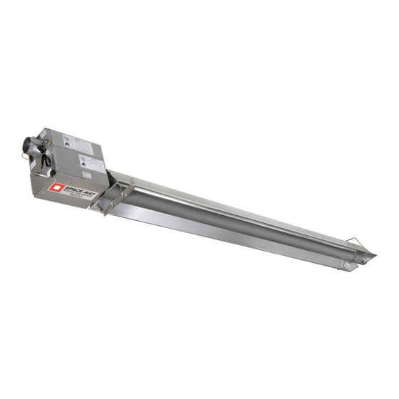
INSTALLATION AND OPERATION INSTRUCTIONS
INFRARED RADIANT POULTRY TUBE HEATER
Single and Two Stage Push Through System (Positive Pressure)
(Hot Rolled Steel)
PCS75 (N5,L5,N7,L7)
PCS100 (N5,L5,N7,L7)
PCS125 (N5,L5,N7,L7)
PCS150 (N5,L5,N7,L7
OWNER / INSTALLER: For your safety this manual must be carefully and thoroughly read and understood before
installing, operating or servicing this heater. This heater is intended for use with either Natural Gas or Propane
Gas. It must be installed by a qualified service person or a licensed contractor in accordance with state and local
codes. In the absence of these codes, the installation must conform to the National Fuel Gas Code ANSI Z223.1
(latest edition), also known as NFPA54 or the Natural Gas and Propane Installation Code CSA B149.1 in Canada.
▲WARNING: Improper installation, adjustment, alteration, service, or maintenance can cause property damage,
injury or death. Read the installation, operation and maintenance instructions thoroughly before installing or
servicing this equipment. For assistance or additional information, consult a qualified installer, service agency or
the gas supplier.
INSPECT all combustion air openings into the building and, if necessary, clear as they become blocked by litter,
dust, feathers or other matter.
FOR YOUR SAFETY: Exhaust fans MUST be operating on an appropriate cycle when heaters are operating to
avoid a high concentration of carbon monoxide. When used without fresh air, this heater may give off carbon
monoxide, an odorless and poisonous gas. CARBON MONOXIDE POISONING MAY LEAD TO DEATH. Early signs of
carbon monoxide poisoning resemble the flue with headaches, dizziness and nausea. If you experience these
signs, GET FRESH AIR IMMEDIATELY! Have the heaters serviced as soon as possible and check the ventilation in
the house.
These heaters are designed for agricultural applications and may operate with the use of either Natural Gas or
Liquid Propane (LP) Gas. Check the heater's nameplate to determine the correct gas type before proceeding
with installation.
!INSTALLER: This manual is the property of the owner. Please present this manual to the owner when you leave
the job site.
IF YOU SMELL GAS:
! DO NOT try to light any appliance.
! DO NOT touch any electrical switch; DO NOT use any
telephone in your building.
! IMMEDIATELY call your gas supplier from a neighbor's
telephone. Follow the gas supplier's instructions. If you
cannot reach your gas supplier, call the fire department.
Scan warranty QR code on the right to
register your product.
!IMPORTANT: SAVE THIS MANUAL FOR FUTURE REFERENCE.
Post Office Box 36485 (28236) • 1700 Parker Drive (28208) • Charlotte, North Carolina
Phone (704) 372-3488 • Fax (704) 332-5843 • www.spaceray.com • email: info@spaceray.com
Models:
(Aluminized Steel)
PCA75 (N5,L5,N7,L7)
PCA100 (N5,L5,N7,L7)
PCA125 (N5,L5,N7,L7)
PCA150 (N5,L5,N7,L7)
FOR YOUR SAFETY
DO NOT store or use gasoline or other
flammable vapors and liquids in the vicinity of
this or any other appliance.
SPACE-RAY
Haga clic aquí para ver
este manual en español.
Form 43343060
April 2022
Advertisement
Table of Contents
Troubleshooting

Related Manuals for Space-Ray PCA Series


Summary of Contents for Space-Ray PCA Series
- Page 1 !IMPORTANT: SAVE THIS MANUAL FOR FUTURE REFERENCE. SPACE-RAY Post Office Box 36485 (28236) • 1700 Parker Drive (28208) • Charlotte, North Carolina Phone (704) 372-3488 • Fax (704) 332-5843 • www.spaceray.com • email: info@spaceray.com...
-
Page 2: Table Of Contents
TABLE OF CONTENTS SECTION DESCRIPTION PAGE 1.0) SAFETY ..............................2 2.0) INSTALLER RESPONSIBILITY ......................2 3.0) GENERAL INFORMATION ........................2 4.0) MINIMUM CLEARANCES TO COMBUSTIBLES ................. 4 5.0) SPECIFICATIONS ..........................5 6.0) PACKING LIST ............................. 5 6.1) ACCESSORY PACKAGES ........................8 7.0) TYPICAL ASSEMBLY LAYOUTS –... -
Page 3: Safety
1.0) SAFETY This heater is a self-contained infrared radiant tube heater designed for use in poultry applications. Safety information required during installation and operation of this heater is provided in this manual and the labels on the product. The installation, service and maintenance of this heater must be performed by a contractor qualified in the installation and service of gas fired heating equipment. - Page 4 Although these heaters may be used in many applications other than space heating (e.g., process heating), Space-Ray will not recognize the warranty for any use other than space heating. This heater is not an explosion proof heater. Where the possibility of exposure to volatile and low flash point materials exists, it could result in property damage or death.
-
Page 5: Minimum Clearances To Combustibles
NFPA54 requires that the installer must post signs that will “specify the maximum permissible stacking height to maintain the required clearances from the heater to combustibles.” Space-Ray recommends posting these signs adjacent to the heater thermostat or other suitable location that will provide enhanced visibility. -
Page 6: Specifications
* Orifice sizes are for altitudes from 0 to 2,000 feet (0 to 610 m). ** MOUNT HEATERS AS HIGH AS POSSIBLE. Minimums are shown as a guideline for human comfort and uniform energy distribution for complete building heating applications. Consult your Space-Ray representative for the particulars of your installation requirements. - Page 7 BURNER PACKAGE NUMBERS SINGLE STAGE CONTROLS TWO STAGE CONTROLS MODEL NO. PART NO. GAS TYPE MODEL NO. PART NO. GAS TYPE PCS/A 75-N5 44165010 NATURAL PCS/A 75/50-N7 44165510 NATURAL PCS/A 100-N5 44165030 NATURAL PCS/A 100/65-N7 44165530 NATURAL PCS/A 125-N5 44165050 NATURAL PCS/A 125/80-N7 44165550...
- Page 8 STANDARD ACCESSORIES Part # Description 30285000 Manual Cut Off Valve – CSA listed ball valve ½” (packaged with control unit) 30302360 Gas connector, 5/8” OD x 36” (packaged with control unit) 44129500 Kit, Fresh Air Intake – Ceiling 44129510 Kit, Fresh Air Intake – Sidewall (includes 4” fresh air intake cap) 43341000 Kit, Reflector End Panels (packaged with control unit) 42924100...
-
Page 9: Accessory Packages
C. PCA (Aluminized Steel System) Body Package Descriptions (Package Part Number is indicated on the outside of each corresponding carton.) 20Ft. 30Ft. 40Ft. 50Ft. Systems System System System System 20 Ft. pkg 30 Ft. pkg 40 Ft. pkg 50 Ft. pkg PCA Body Packages –Aluminized 44055200 44055300... - Page 10 B. U-Bend Package, Part #43208021 (Option for U Configuration Series Only) Contains: U-Bend, #42913020……QTY–1 Tube Coupling, #30462980……QTY–1 Wire Hanger, #43980010……QTY–1 31” Tube Support/Hanger Bracket, #43318500……QTY–1 #10-16 x ½ Self-Drilling Screws, #02189020……QTY–2 C. U-Bend Reflector Package, Part #43488000 (Option for U Configuration Series Only) Contains: U-Bend Reflector, #43490000……QTY–1 U-Bend End Reflector, #43490050……QTY–1...
- Page 11 F. Fresh Air Inlet (Through Ceiling) Package, Part #44129500 Contains: a) 4” Air Intake Assembly, #44129000……QTY–1 b) 4” x 30” Flexible Hose, #30675020 QTY-1 c) 4” Screw Clamp, #30676049 QTY-2 d) #12 x ¾” Sheet Metal Screws, #02240010……QTY–4 G. Fresh Air Inlet (Through Sidewall) Package, Part #44129510 Contains: a) 4”...
-
Page 12: Typical Assembly Layouts - Straight Configuration
7.0) TYPICAL ASSEMBLY LAYOUTS – STRAIGHT CONFIGURATION EMITTER LENGTH 2 Ft. Turbulator MODEL Min. Max. Sections PCS/PCA 75 20 Ft. 30 Ft. PCS/PCA 100 30 Ft. 40 Ft. PCS/PCA 125 30 Ft. 50 Ft. PCS/PCA 150 40 Ft. 60 Ft. Form 43343060 April 2022 -11-... -
Page 13: Typical Assembly Layouts - With Optional U Bend
7.1) TYPICAL ASSEMBLY LAYOUTS – WITH OPTIONAL U BEND MODEL EMITTER LENGTH BODY LENGTH* PCS/PCA 75 20 Ft. 10 Ft. PCS/PCA 100, 125, 150 40 Ft. 20 Ft. PCS/PCA 150 60 Ft. 30 Ft. * Plus U-Bend NOTES: 1. In all configurations, the control unit must be connected directly to a 10 ft. aluminized steel body section in all systems. -
Page 14: Dimensions - Straight Configuration
8.0) DIMENSIONS – STRAIGHT CONFIGURATION Form 43343060 April 2022 -13-... -
Page 15: Dimensions - With Optional U Bend
8.1) DIMENSIONS – WITH OPTIONAL U BEND Form 43343060 -14- April 2022... -
Page 16: Heater Assembly / Joining Of Tube Sections
8.2) HEATER ASSEMBLY / JOINING OF TUBE SECTIONS Form 43343060 April 2022 -15-... - Page 17 Form 43343060 -16- April 2022...
-
Page 18: Typical Suspension Methods
6. Heaters must not be supported by gas or electric supply lines and must be suspended from a permanent structure with adequate load capacity. Space-Ray recommends that the body sections be suspended using chains with turnbuckles. This will allow slight adjustments after assembly and heater expansion/ contraction during operation. -
Page 19: Assembly Of Tube Sections
Consult your Space-Ray Representative if you have any questions prior to the installation concerning particulars of your application. -
Page 20: Assembly Of Extension Section
5. Suspend the chain to attach the wire hanger and the tube support bracket. Insert the tube into the wire hanger and then raise the tube support bracket end up to the suspension chain, use “S” hooks to attach the wire hanger and tube support bracket to the chain. - Page 21 See typical assembly overview (Section 8.0) for typical complete assembly. Assemble additional extension sections as required for all systems. (See Sections 7.0), and 8.0) for typical layout details.) Join the tube sections together and secure with tube couplings as described below: The following coupling tightening instructions MUST be followed properly to ensure the integrity of the tube connections.
-
Page 22: Inserting Turbulators
8. Check to ensure that the hardware is completely closed and the band is seated on the reaction block and interference pins as illustrated above. 9. Once all the heater body sections are attached, make sure that the heater system is level. If it is not, slight adjustments can be made using the turnbuckles. -
Page 23: Adding Body Reflectors
10.3) ADDING BODY REFLECTORS 1. Slide the reflectors on the tube support/hanger brackets and through the wire hangers. 2. The tube at the coupling joints must be covered. Slide the reflectors together and provide an overlap of two (2”) inches for the first reflector overlap after the control unit. All remaining reflector overlaps will be approximately one (1”) inch. -
Page 24: Adding 180º U-Bend (20 Ft, 40 Ft And 60 Ft Systems Only)
10.4) ADDING 180º U-BEND (20 FT, 40 FT AND 60 FT SYSTEMS ONLY) 1. Hang body sections parallel with each other. The centerline distance from tube at each body section should be 18” as shown. 2. Join tube ends of body sections and the U-Bend together and secure with tube couplings as described in Section 10.1). -
Page 25: Attaching Burner Box Assembly
11.0) ATTACHING BURNER BOX ASSEMBLY 1. Attach the burner box and gasket to end of tube flange and secure with 1/4-20 locknuts. 2. Assemble the optional end reflector flush with the end of the main body reflector. Secure by sliding speed clips onto the reflector edges. -
Page 26: 11.1) Connecting The Tiss System
11.1) CONNECTING THE TISS SYSTEM Description: The TISS (Tube Integrity Safety System) is designed to shut the main burner off in the event that a burnout occurs in the first 10ft. section of firing tube. Note: When replacing the firing tube a new TISS wire assembly PN 44176510 (spring and spring retainer clamp not included) must also be installed. - Page 27 3. Hold the spring retainer clamp and pull the TISS wire assembly to end of reflector at overlap joint. Slide spring retainer clamp over end of reflector as shown. Step 3 4. After attachment of the TISS, check to make sure that there is sufficient tension on the wire. Follow the diagram below to increase or decrease the tension as necessary.
- Page 28 ANGLE MOUNTED HEATERS ONLY 5. If heaters are to be angle mounted, the TISS wire holder clamp must first be re-positioned as shown using the bottom hole pattern of the clamp. Follow procedures described earlier for all other adjustments. Step 5 Failure to re-position the wire clamp at the bottom hole pattern will shorten the life expectancy of the TISS wire assembly.
-
Page 29: Gas Connections And Regulations
12.0) GAS CONNECTIONS AND REGULATIONS IMPORTANT BEFORE CONNECTING THE GAS TO THE HEATER 1. Connect to the supply tank or manifold in accordance with the latest edition of National Fuel Gas Code (ANSI Z223.1), and local building codes. Authorities having jurisdiction should be consulted before the installation is made. - Page 30 US ONLY: Connector MUST be installed in “” configuration. Use only the 36” long connector that was furnished with this heater. US ONLY: A gas connector certified for use on a tubular type infrared heater per the standard for Connectors for Gas Appliances, ANSI Z21.24/CSA 6.10 is supplied for installation in US only.
-
Page 31: Instructions For Pressure Test Gauge Connection
13.0) INSTRUCTIONS FOR PRESSURE TEST GAUGE CONNECTION SUPPLY PRESSURE 1. The installer will provide a 1/8” N.P.T. tapped plug, accessible for test gauge connection immediately upstream of the gas supply connection to the heater. OUTLET GAS PRESSURE CHECK AND ADJUSTMENTS Gauges that measure pressure in pounds per square inch are not accurate enough to measure or set the manifold pressure. - Page 32 Figure 1 TO ADJUST REGULATOR (two stage gas valves): Turn on power and energize main gas valve solenoid. Do not energize the HI solenoid. Remove regulator cover screw from the low outlet pressure regulator (see Figure 2 below) and turn screw ...
-
Page 33: Electrical Connections
GAS PRESSURE TABLE SUPPLY PRESSURE MANIFOLD PRESSURE GAS TYPE High Low (2-stage only) Minimum* Maximum Natural Gas 3.5” W.C. 1.4” W.C. 5” W.C. 14” W.C. Propane Gas 10.0” W.C. 4.0” W.C. 11” W.C. 14” W.C. *Minimum permissible gas supply pressure for purpose of input adjustment. 7”... -
Page 34: Single Stage (N5/L5) Internal And Thermostat Connections
14.1) SINGLE STAGE (N5/L5) INTERNAL AND THERMOSTAT CONNECTIONS SINGLE STAGE CONTROLS - INTERNAL CONNECTION WIRING DIAGRAM SINGLE STAGE CONTROLS - SCHEMATIC WIRING IGNITION MODULE TERMINAL DESIGNATIONS DIAGRAM 24VAC/R 24 VAC Supply to Module TH/W Thermostat Input PS/W Pressure Switch Input System Ground Valve Power Valve Ground... - Page 35 SINGLE STAGE CONTROLS - THERMOSTAT WIRING DIAGRAMS SINGLE STAGE CONTROLS L. LINE VOLTAGE (120V) THERMOSTAT CONNECTIONS – SINGLE HEATER M. LINE VOLTAGE (120V) THERMOSTAT CONNECTIONS – MULTIPLE HEATERS Form 43343060 -34- April 2022...
-
Page 36: Two Stage (N7/L7) Internal And Thermostat Connections
N. LOW VOLTAGE (24V) THERMOSTAT CONNECTIONS – SINGLE HEATERS O. LOW VOLTAGE (24V) THERMOSTAT CONNECTIONS – MULTIPLE HEATERS (utilizing a fan center relay) 14.2) TWO STAGE (N7/L7) INTERNAL AND THERMOSTAT CONNECTIONS TWO STAGE CONTROLS - INTERNAL CONNECTION WIRING DIAGRAM Form 43343060 April 2022 -35-... - Page 37 TWO STAGE CONTROLS - SCHEMATIC WIRING IGNITION MODULE TERMINAL DESIGNATIONS DIAGRAM 24VAC/R 24 VAC Supply to Module TH/W Thermostat Input PS/W Pressure Switch Input System Ground Valve Power Valve Ground 120/240 VAC Input (Hot) Blower Output TWO STAGE CONTROLS - THERMOSTAT WIRING DIAGRAMS TWO STAGE CONTROLS Form 43343060 -36-...
- Page 38 A. LOW VOLTAGE (24V) THERMOSTAT CONNECTIONS – SINGLE HEATERS B. LOW VOLTAGE (24V) THERMOSTAT CONNECTIONS – MULTIPLE HEATERS Form 43343060 April 2022 -37-...
-
Page 39: Recommended Thermostat Sensor Location
C. LOW VOLTAGE (24V) 3 WAY MANUAL SWITCH CONNECTIONS – MULTIPLE HEATERS 14.3) RECOMMENDED THERMOSTAT SENSOR LOCATION The thermostat sensor should be located approximately 10ft from side of the heater as shown in Figure 1 and at distances from burner box as shown in chart of Figure 2 below. Ideally this should also be located between the feed and drink lines. - Page 40 Figure 1 Figure 2 Form 43343060 April 2022 -39-...
-
Page 41: Remote Operation Signal Communication
14.4) REMOTE OPERATION SIGNAL COMMUNICATION This optional remote heater operation signal communication is available for both the single and two stage heater models. Each heater must be connected to its individual signal LED. The wire connection is made as indicated below in the respective wiring diagram. Signal voltage: 24Vac Maximum wire length: 300 ft Minimum wire gauge: 20ga... - Page 42 Wire connections (two stage controls) on push burner are as below: Form 43343060 April 2022 -41-...
-
Page 43: Venting
15.0) VENTING This is a category lll appliance. A. BASIC FLUE VENTING — Venting must comply with the latest edition of the National Fuel Gas Code (ANSI Z223.1-latest edition) or the authority having jurisdiction. Other venting references are in the equipment volume of the ASHRAE Handbook. - Page 44 SINGLE HEATER VENTING (VERTICAL THROUGH THE ROOF) 1. When venting the heater to outside of building through a roof, use single-wall metal pipe. This is to be constructed of galvanized sheet metal or other approved noncombustible corrosion-resistant material as allowed by state or local codes. 2.
- Page 45 6. A minimum clearance of 6 inches must be maintained between the outside wall and vent cap (18” clearance will provide stability under high wind conditions). 7. The horizontal venting system shall not terminate: • Less than 4 ft. (1.2m) below, 4 ft. (1.2m) horizontally from or 1 ft. (30cm) above any door, operable window or gravity air inlet into any building.
-
Page 46: Air For Combustion
16.0) AIR FOR COMBUSTION If indoor combustion air is to be supplied for a tightly enclosed area, one square inch of free area opening shall be provided below the heater for each 1,000 Btu/hr of heater input. When outside air is used, the opening below the heater shall be one square inch of free area for each 4,000 Btu/hr of heater input. -
Page 47: Air For Combustion - Through Ceiling
16.2) AIR FOR COMBUSTION – THROUGH CEILING If the heater is installed less than 2 ft. from the ceiling, a flexible transition section must be used to allow for expansion/contraction of straight tube heaters. Install the fresh air intake assembly (supplied in accessory Kit no. 44129500) shown below. -
Page 48: Lighting And Shutdown Instructions
17.0) LIGHTING AND SHUTDOWN INSTRUCTIONS 1. Turn on the gas and electrical supply. 2. Set the thermostat to call for heat. The blower motor will energize. 3. Ignition should occur after the 15-second pre-purge. 4. If the burner fails to light, or flame is not detected during the first trial for ignition (a period of approximately 15 seconds) the gas valve is de-energized and the control goes through an inter-purge delay of approximately 60 seconds before another ignition attempt. -
Page 49: Sequence Of Operation - Two Stage (N7/L7)
Note: When the PCS / PCA is operated by a thermostat interrupting the line voltage (120V) to the heater then the post purge function is disabled. If the flame is not sensed during sequence T3 then the burner will automatically begin re-ignition sequence T2. The ignition sequence will be repeated three times with a 60 second inter-purge. -
Page 50: Control Component Location
19.0) CONTROL COMPONENT LOCATION Form 43343060 April 2022 -49-... -
Page 51: Cleaning And Annual Maintenance
20.0) CLEANING AND ANNUAL MAINTENANCE This heater must be cleaned and serviced annually by a qualified contractor before the start of each heating season and at any time excessive accumulation of dust and dirt is observed. Maximum heating efficiency and clean combustion will be maintained by keeping the heater clean. -
Page 52: Troubleshooting Guide - Single Stage (N5/L5)
21.0) TROUBLESHOOTING GUIDE – SINGLE STAGE (N5/L5) Form 43343060 April 2022 -51-... - Page 53 TROUBLESHOOTING GUIDE – SINGLE STAGE (CONTINUED) Form 43343060 -52- April 2022...
- Page 54 TROUBLESHOOTING GUIDE – SINGLE STAGE (CONTINUED) Form 43343060 April 2022 -53-...
-
Page 55: Troubleshooting Guide - Two Stage (N7/L7)
21.1) TROUBLESHOOTING GUIDE – TWO STAGE (N7/L7) Form 43343060 -54- April 2022... - Page 56 TROUBLESHOOTING GUIDE – TWO STAGE (CONTINUED) Form 43343060 April 2022 -55-...
- Page 57 TROUBLESHOOTING GUIDE – TWO STAGE (CONTINUED) Form 43343060 -56- April 2022...
-
Page 58: Replacing Parts
22.0) REPLACING PARTS Only use genuine Space-Ray replacement parts. Parts are available from the factory for replacement by a licensed person. Refer to the Replacement Parts Guide in Section 24.0) for all replacement parts. 22.1) REMOVAL OF MAIN BURNER AND ELECTRODES The main burner can be inspected without removing the burner housing from the heat exchanger tube. -
Page 59: Removing Gas Valve And Manifold Assembly
22.2) REMOVING GAS VALVE AND MANIFOLD ASSEMBLY 22.3) AIR SWITCH PRESSURE CHECK Form 43343060 -58- April 2022... -
Page 60: Ignition System Checks
1. Open hinged access panel. 2. Add tubing to connect the air switch tubing P1 + and P2 - with the connector tees and the probes P1+ and P2+. 3. Connect plastic tubing of a digital or inclined water manometer with a 0-2” scale onto the connector tees. 4. -
Page 61: Installation Data
IGNITION MODULE DIAGNOSTICS Flame Fault If at any time the main valve fails to close completely and maintains a flame, the full time flame sense circuit will detect it and energize the combustion blower. Should the main valve later close completely removing the flame signal, the combustion blower will power off following the post purge period. -
Page 62: Replacement Parts Guide
24.0) REPLACEMENT PARTS GUIDE BURNER BOX Item No. Part No. Description Qty. Fasteners 02295040 PHTCS #6-32 x 3/8" 02266010 Speed Clips (for air inlet plate) 02261030 HHTCS #8-32 x 3/8" (green coated) 02242050 PHTCS #8-32 x 3/8" 02242070 PHTCS #8-32 x 1/2” 02123170 RHMS #8-32 x 3/4"... - Page 63 Labels/Manual 42848070 Label, Nameplate – Single Stage 42848090 Label, Nameplate – Two Stage 42013000 Label, Logo (Space-Ray) (Not Shown) 43344080 Label, Clearances to Combustibles 42874020 Label, Wire Connection Diagram – Single Stage 42874030 Label, Wire Connection Diagram – Two Stage...
- Page 64 Form 43343060 April 2022 -63-...
- Page 65 ALL ILLUSTRATIONS ARE INTENDED TO GIVE THE GENERAL IMPRESSION OF UNITS ONLY. OTHER COMBINATIONS OF 5 FT. AND 10 FT. SECTIONS, AND ONES WITH OR WITHOUT THE ELBOW PACKAGE ARE POSSIBLE. PLEASE CONSULT WITH YOUR SPACE-RAY SALES REPRESENTATIVE. WE RESERVE THE RIGHT TO ALTER ANY SPECIFICATION WITHOUT NOTICE. Form 43343060...
-
Page 66: Warnings Card
25.0) WARNINGS CARD Copies of this card may be ordered at no charge under part no. 43344990 for installation near the heater. Form 43343060 April 2022 -65-... - Page 67 GAS-FIRED PRODUCTS LIMITED WARRANTY LIMITED WARRANTY Gas-Fired Products, Inc. (GFP), the manufacturer, warrants the original owner of any Space-Ray Poultry Heating Product that it will be free from defects in material or workmanship under normal use and service. The heater(s) shall be installed, used and maintained strictly in accordance with the manufacturer’s instructions.
- Page 68 For the name of your nearest distributor in case of claim under this warranty, contact: Space-Ray Poultry Heating Products / Gas-Fired Products, Inc. / 1700 Parker Drive., P.O. Box 36485 / Charlotte, NC 28236 / Phone: (704) 372-3488 / Fax: (704) 332-5843 / email: info@spaceray.com.
Need help?
Do you have a question about the PCA Series and is the answer not in the manual?
Questions and answers