Space-Ray LTU SERIES Installation And Operation Instructions Manual
Ltu / lts series infrared radiant tube heater
Hide thumbs
Also See for LTU SERIES:
Table of Contents
Advertisement
INSTALLATION AND OPERATION INSTRUCTIONS
OWNER / INSTALLER: For your safety this manual must be carefully and thoroughly read
and understood before installing, operating or servicing this heater.
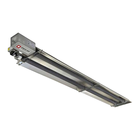
INFRARED RADIANT TUBE HEATER
LTU SERIES:
LTS SERIES:
^ INSTALLER: This manual is the property of the owner. Please present this manual to
the owner when you leave the job site.
WARNING: Improper installation, adjustment, alteration, service, or maintenance can
cause property damage, injury or death. Read the installation, operation and maintenance
instructions thoroughly before installing or servicing this equipment.
^ IMPORTANT: SAVE THIS MANUAL FOR FUTURE REFERENCE.
Post Office Box 36485
Phone (704) 372-3485
Models:
(40, 50, 60, 75, 80, 90, 100, 110, 120, 125,
130, 140, 150, 160, 175, 180, 200, 225, 250)
(40, 50, 60, 75, 80, 90, 100, 110, 120, 125,
130, 140, 150, 160, 175, 180, 200, 225, 250)
SPACE-RAY
305 Doggett Street
(28236)
Fax (704) 332-5843
www.spaceray.com
Charlotte, North Carolina
(28203)
email:
info@spaceray.com
Form #43155260
Mar–05
Advertisement
Table of Contents

Subscribe to Our Youtube Channel
Related Manuals for Space-Ray LTU SERIES


Summary of Contents for Space-Ray LTU SERIES
-
Page 1: Installation And Operation Instructions
OWNER / INSTALLER: For your safety this manual must be carefully and thoroughly read and understood before installing, operating or servicing this heater. INFRARED RADIANT TUBE HEATER Models: LTU SERIES: (40, 50, 60, 75, 80, 90, 100, 110, 120, 125, 130, 140, 150, 160, 175, 180, 200, 225, 250) LTS SERIES:... -
Page 2: Table Of Contents
TABLE OF CONTENTS DESCRIPTION PAGE 1.0) General Information ..........................2 2.0) LTU 40-250 Series — Specifications ..................... 3 3.0) LTU 40-75 Series — Packing List......................4 3.1) LTU 80-250 Series — Packing List ......................4 4.0) LTU (40-75)-30 Series — Dimensions ....................6 4.1) LTU (80-130)-30 Series —... -
Page 3: General Information
225-250 models. Heaters may be mounted at various heights and angles depending on the application. If you have any questions, please consult your local Space-Ray representative. Every heater shall be located with respect to building construction and other equipment so as to permit access to the heater. -
Page 4: Ltu 40-250 Series - Specifications
2.0) LTU 40-250 SERIES — SPECIFICATIONS Minimum Heat Total Orifice Size Mounting Height Btu/hr Exchanger Heater Flue Restrictor Model No. Input Length Length Plate I.D. & Part # Natural Gas Propane Gas Horizontal 45º Angle LTU40 40,000 1” #42741040 10’ 9’... -
Page 5: Ltu 40-75 Series - Packing List
3.0) LTU 40-75 SERIES — PACKING LIST Control/Draft Inducer Package CONTROL/DRAFT INDUCER Control Box Assembly ..........(Refer to Package Part Numbers at right) PACKAGE NUMBERS: Draft Inducer Assembly (with 4” Starting Collar) ..(Refer to Package Part Numbers at right) MODEL NO. - Page 6 Body Package Descriptions (Package Number is indicated on the outside of each corresponding carton.) LTU 80–130 (30’ TUBE) Each 30’ LTU tube heater contains one 15’ Body Package as listed below. (1) #42881000, 15 Ft. Body Package containing: (QTY=1) a) #42914000, Pre-assembled 15’ ALC steel U-tube (two 24-hole flanges) with Reflector (QTY=1) b) #42895000, Control End Reflector (QTY=1)
-
Page 7: Ltu (40-75)-30 Series - Dimensions
4.0) LTU (40-75)-30 SERIES — DIMENSIONS 4.1) LTU (80-130)-30 SERIES — DIMENSIONS Form #43155260 –6– Mar–05... -
Page 8: Ltu (125-175)-40 Series - Dimensions
4.2) LTU (125-175)-40 SERIES — DIMENSIONS 4.3) LTU (180-250)-50 SERIES — DIMENSIONS 4.4) LTU 80-250 SERIES — DIMENSIONS Form #43155260 Mar–05 –7–... -
Page 9: Ltu 40-75 Series - Heater Assembly
5.0) LTU 40-75 SERIES — HEATER ASSEMBLY Loosen the reflector clamps on the tube support/hanger brackets as shown on the next page. Do not relocate the tube support/hanger brackets, especially at the control box end of the heater. Slide the end of the main reflector back to the first tube support/hanger bracket. Place the flanges of the control end reflector flush with the end of the main body reflector. - Page 10 Form #43155260 Mar–05 –9–...
-
Page 11: Ltu 80-175 Series - Heater Assembly
5.1) LTU 80-175 SERIES — HEATER ASSEMBLY Place the flanges of the control end reflector (packaged with the 15’ body section) flush with the end of the body reflector. Secure by sliding the speed clips onto the reflector edges. Evenly space the speed clips on the sides and top of the reflector to provide a snug fit. -
Page 12: Ltu 125-250 Series - Joining Of Body Sections
5.2) LTU 125-250 SERIES — JOINING OF BODY SECTIONS MODELS LTU(125–175)-40 These models require the use of an additional 5 ft. body section, as shown on the heater dimension sheet. MODELS LTU(180–250)-50 These models require the use of an additional 10 ft. body section, as shown on the heater dimension sheet. -
Page 13: Ltu (180-250)-50 Series - Typical Assembly Layout
5.3) LTU (180-250)-50 SERIES — TYPICAL ASSEMBLY LAYOUT IMPORTANT Form #43155260 –12– Mar–05... -
Page 14: Lts 40-250 Series - Specifications
6.0) LTS 40-250 SERIES — SPECIFICATIONS Minimum Orifice Size Mounting Height Btu/hr Flue Restrictor Model No. Input Plate I.D. & Part # Natural Gas Propane Gas Horizontal 45º Angle LTS 40 40,000 1” #42741040 10 ft. 9 ft. (0.120) (0.073) LTS 50 50,000 1-1/8”... -
Page 15: Lts 40-250 Series - Packing List
7.0) LTS 40-250 SERIES — PACKING LIST Control/Draft Inducer Package CONTROL/DRAFT INDUCER PACKAGE NUMBERS: Control Box Assembly ......................MODEL NO. PART NO. Draft Inducer & Junction Box Assembly ................— NATURAL GAS — LTS40-N5 #43187010 4” x 6” Starting Collar (#42892000) ................ - Page 16 LTS 40-175 Body Package Descriptions (Package Number is indicated on the outside of each corresponding carton.) SYSTEM LENGTH 15’ 20’ 25’ 30’ 35’ 40’ 45’ 50’ (1) #43337040, Start/End 10 Ft. Body Package – includes: Quantity = a) #43182060, Pre-assembled 10’ ALC Steel Tube (one 24-hole flange) with reflector (QTY=1) b) #30462980, Tube Coupling...
- Page 17 LTS 225-250 Body Package Descriptions (Package Number is indicated on the outside of each corresponding carton.) SYSTEM LENGTH 50’ 55’ 60’ 65’ 70’ 75’ 80’ (1) #43337050, Starting 10 Ft. Body Package – includes: Quantity = a) #43182023, Pre-assembled 10’ ATC Steel Tube (two 6-hole flanges) with reflector (QTY=1) b) #43320000, End Reflector (QTY=1)
-
Page 18: Accessory Packages
8.0) ACCESSORY PACKAGES A) Elbow Accessory Package, Part #43208010 (Option for LTS Series Only) Contains: Elbow, #431750010……QTY–1 #10-16 x ½ Self-Drilling Screws, #02189020……QTY–2 Tube Coupling, #30462980……QTY–1 B) Corner Reflector Accessory Package, Part #43342000 (Option for LTS Series Only) Contains: Corner Reflector Assembly, #43345000……QTY–1 Speed Clips, #02266010……QTY–4 C) Exhaust Hood Package, Part #42924000 Contains:... -
Page 19: Lts 40-250 Series - Typical Layouts
9.0) LTS 40-250 SERIES — TYPICAL LAYOUTS Straight U Shape L Shape Z Shape EMITTER LENGTH MODEL Min. Max. LTS 40 15 Ft. 20 Ft. LTS 50 15 Ft. 30 Ft. LTS 60 20 Ft. 30 Ft. LTS 75 20 Ft. 30 Ft. -
Page 20: Lts 180-250 Series - Typical Assembly Layouts
9.1) LTS 180-250 SERIES — TYPICAL ASSEMBLY LAYOUT 10.0) LTS 40-250 SERIES — DIMENSIONS Form #43155260 Mar–05 –19–... -
Page 21: Lts 40-250 Series - Heater Assembly / Joining Of Body Sections
11.0) LTS 40-250 SERIES — HEATER ASSEMBLY / JOINING OF BODY SECTIONS During field assembly of the LTS series heater body sections, the recommended procedure is as follows: Before hanging heater sections, first determine the actual layout of the system (see Section 9 for details). Consideration must also be taken for flue pipe, fresh air ducting, gas piping, etc. -
Page 22: Lts 225-250 Series - Joining Of Body Sections
COUPLING (side view) 11.1) LTS 225-250 SERIES — JOINING OF BODY SECTIONS The control box must be attached to a 6-hole flange on the 10 ft. Starting Body Package (this body package has a 6-hole flange at both ends of the tube). The other 6-hole flange must be connected to a 24-hole flange on the body package for LTS225-250models. -
Page 23: Adding Optional 90º Elbow (Lts Only)
10FT Secondary Body Section 10FT Starting Body Section 12.0) ADDING OPTIONAL 90º ELBOW (LTS ONLY) The optional 90º elbow must be located a minimum of 10 ft. after the control box. Hang the body sections in a 90º ("L") shaped pattern. Allow spacing for the elbow. The distance from one end of the elbow to the centerline of the opposite leg is 13"... -
Page 24: Adding Optional Corner Reflector (Lts Only)
12.1) ADDING OPTIONAL CORNER REFLECTOR (LTS ONLY) Place the corner reflector over the reflectors of both body sections. Secure by sliding speed clips on the reflector edges. One speed clip is required for each side of reflector. The corner reflector can be used only when the long axis of the heater is level and mounted in a horizontal position. Form #43155260 Mar–05 –23–... -
Page 25: Attaching Control Box Assembly
13.0) ATTACHING CONTROL BOX ASSEMBLY Attach the control box and gasket to end of tube flange and secure with 1/4-20 locknuts. NOTE: The control box must be mounted to a 10 ft. aluminized steel body section for 40-200 MBtu/hr models, or to a 10 ft. Alumi-Therm steel body section for 225-250 MBtu/hr models, regardless of configuration used. -
Page 26: Attaching Draft Inducer Assembly
NOTE: The draft inducer can be mounted in a vertical, a 45º, or a horizontal position. Refer to the diagram on Multiple Hanging and Draft Inducer Positions (Section 15.1). Disconnect the piece of SJO cable (if equipped) from the junction box and discard. This is used only on LTU series heaters. -
Page 27: Multiple Hanging & Draft Inducer Positions
15.0) MULTIPLE HANGING & DRAFT INDUCER POSITIONS — LTU (40-75)-30 SERIES The heater can be mounted horizontally or up to an angle of 45º maximum from horizontal. When the heater is to be angle mounted, make sure the draft inducer assembly is on the lower side of the heater. Make sure the long axis of heater is level. - Page 28 Form #43155260 Mar–05 –27–...
-
Page 29: Typical Suspension Methods
Heaters must not be supported by gas or electric supply lines and must be suspended from a permanent structure with adequate load capacity. Space-Ray recommends that the body sections be hung by chains with turnbuckles. This will allow slight adjustments after assembly and heater expansion/ contraction during operation. -
Page 30: Inclined Mounting Instructions (Lts Only)
15.3) INCLINED MOUNTING INSTRUCTIONS (LTS ONLY) These inclined mounting instruction relate to LTS series heaters (straight tubes) that do not utilize the elbow accessory. These heaters have been tested and design certified by the CSA for 2”/12” pitch (10º) inclined mounting of the heater from the control box to the draft inducer assembly as shown in the following diagram. -
Page 31: Minimum Clearances To Combustibles
NFPA54 requires that the installer must post signs that will “specify the maximum permissible stacking height to maintain the required clearances from the heater to combustibles.” Space-Ray recommends posting these signs adjacent to the heater thermostat or other suitable location that will provide enhanced visibility. -
Page 32: Gas Connections And Regulations
17.0) GAS CONNECTIONS AND REGULATIONS Connect to the supply tank or manifold in accordance with the latest edition of National Fuel Gas Code (ANSI Z223.1), and local building codes. Authorities having jurisdiction should be consulted before the installation is made. (In Canada, refer to the latest edition of CAN Standard B.149-1 &... -
Page 33: Instructions For Pressure Test Gauge Connection
17.1) INSTRUCTIONS FOR PRESSURE TEST GAUGE CONNECTION SUPPLY PRESSURE The installer will provide a 1/8” N.P.T. plugged tapping, accessible for test gauge connection immediately upstream of the gas supply connection to the heater. MANIFOLD PRESSURE Turn the gas valve to the “OFF” position. Remove the 1/8” plug from the combination gas valve at the outlet pressure tap and connect a 1/8”... -
Page 34: Electrical Connections
18.0) ELECTRICAL CONNECTIONS All electric wiring shall conform to the latest edition of the National Electrical Code (ANSI/NFPA No. 70), or the code legally authorized in the locality where the installation is made. The unit must be electrically grounded in accordance with the National Electrical Code (ANSI/NFPA No. 70-latest edition). In Canada, refer to current standard C22.1 Canadian Electrical Code Part 1. -
Page 35: Venting
NOTES: If any of the original wire as supplied with the appliance must be replaced, it must be replaced with wiring material having a temperature rating of at least 105ºC. (18 Ga. CSA 600V Type TEW) When connecting the supply circuit to the heater, wiring material having a minimum size of 14 AWG and a temperature rating of at least 90ºC shall be used. - Page 36 SINGLE HEATER VENTING (HORIZONTAL THROUGH SIDEWALL) When venting the heater horizontally through a combustible outside sidewall, the same requirements listed previously for venting Vertical Through The Roof apply except as follows: A vent passing through a combustible wall must pass through a 2-inch clearance thimble (Air-Jet #4VT or #6VT or Ameri-Vent #4EWT or #6EWT) or other thimbles that are listed by a nationally recognized testing agency.
- Page 37 BASIC FLUE VENTING Connections into a Manifold Connections into a Common Vent THE FOLLOWING ILLUSTRATIONS AND TABLE OF VENT SIZES FOR COMMON VENTING OF MULTIPLE HEATERS ARE IN ACCORDANCE WITH THE NATIONAL FUEL GAS CODE ANSI Z223.1-LATEST EDITION, NFPA #54-LATEST EDITION, EQUIPMENT VOLUME OF 1988 ASHRAE HANDBOOK, CURRENT CAN/CGA-B149.1/2-M86 INSTALLATION CODE, AND AGA PUBLICATION NO.
-
Page 38: Air For Combustion
19.1) AIR FOR COMBUSTION If indoor combustion air is to be supplied for a tightly enclosed area, one square inch of free area opening shall be provided below the heater for each 1,000 Btu/hr of heater input. Adequate clearances around the perforated fresh air plate must be maintained at all times. -
Page 39: Lighting And Shutdown Instructions
20.0) LIGHTING AND SHUTDOWN INSTRUCTIONS Turn on the gas supply. Set the thermostat to call for heat. Ignition should occur after the 30-second air purge. If ignition fails, the unit will spark for approximately 21 seconds and go into safety lockout. Turn the thermostat (power) off for 60 seconds to take the system out of lockout. -
Page 40: Sequence Of Operation
22.0) SEQUENCE OF OPERATION THERMOSTAT (or Controller) CALLS FOR HEAT (GREEN light ON) DRAFT INDUCER STARTS (Purge Period) INSUFFICIENT AIRFLOW — SYSTEM SHUTS OFF (RED light OFF) DIAPHRAGM AIR SWITCH ON (RED light ON) FAILURE TO IGNITE — IF NO SPARK, SYSTEM GOES INTO LOCKOUT SYSTEM GOES INTO LOCKOUT (AMBER light OFF) -
Page 41: Troubleshooting Guide Of Direct Spark Ignition System
23.0) TROUBLESHOOTING GUIDE OF DIRECT SPARK IGNITION SYSTEM –START– TURN GAS SUPPLY ON. SET THERMOSTAT TO CALL FOR HEAT. Υ Check line voltage. Power To Control Module? Υ Low voltage transformer. (25 vac nominal) Υ Thermostat and wiring. Υ Diaphragm air switch. Ignition Module 30-Second Υ... -
Page 42: Motor And Blower Wheel Check
24.0) MOTOR AND BLOWER WHEEL CHECK If draft inducer motor fails to run: A) Check power supply to junction box. B) Check for loose or broken motor lead wire. C) Check to see that blower wheel turns freely and is not rubbing housing. Blower wheel may have worked loose from shaft and jammed against housing. -
Page 43: 28.0) Replacement Parts Guide
28.0) REPLACEMENT PARTS GUIDE MODELS: LTU 40-75 DRAFT INDUCER COMPONENTS ITEM NO. PART NO. DESCRIPTION 42917000 Draft Inducer Assembly 03721000 Motor, JB1R061N 30347000 Motor Spacer (4 per motor) 42740000 Motor Plate 03723000 Blower Wheel 43221000 Draft Inducer Gasket 42744000 Sensing Tube, Draft Inducer 42742000 Sensing Tube Bracket 42739000... - Page 44 MODELS: LTU 40-75 CONTROL COMPONENTS ITEM NO. PART NO. DESCRIPTION 03988150 Plastic Vacuum Air Tube, 15” long 42750000 Cabinet Assembly 42751000 Access Panel 42752000 Air Inlet Plate (Perforated) 42447000 Sight Glass 30186201 Air Switch, set @0.11” W.C., #RSS-495-307 30279000 Transformer, AT120B1051 42709000 Terminal Block Shield 30281000...
- Page 45 MODELS: LTS 40-250 and LTU 80-250 DRAFT INDUCER COMPONENTS ITEM NO. PART NO. DESCRIPTION 42917010 Draft Inducer Assembly, 180M–250M Btu/hr models 42917000 Draft Inducer Assembly, 40M–75M Btu/hr models 03723020 Blower Wheel, Beckett 03723000 Blower Wheel, Revcor 03988120 Plastic Vacuum Air Tube, 12” long 42739010 Blower Housing Sub-Assembly 42740000...
- Page 46 Form #43155260 Mar–05 –45–...
- Page 47 MODELS: LTS 40-250 and LTU 80-250 CONTROL COMPONENTS ITEM NO. PART NO. DESCRIPTION 03868010 3/8” Connector 42874000 Connection Wire Diagram (not shown) 30295000 Electrode PSE-GF1 (Igniter/Sensor) 30314120 Ignition Cable, 14” long 30324000 Terminal Block, EK-104 30331040 Spark Module, S87J-1034 30220020 Monitoring Light, Red 30220030 Monitoring Light, Amber...
- Page 48 Form #43155260 Mar–05 –47–...
- Page 49 MODELS: LTU 40-75 LTU BODY COMPONENTS ITEM NO. PART NO. DESCRIPTION 02266010 Reflector Speed Clip 42769011 Reflector Clamp with screw 42770000 “U” Bolt Clamp, 3” OD Tube 02127110 “U” Bolt Hex Nut, 5/16-18 (2 per “U” Bolt) 42773000 Tube Support/Hanger Bracket, 18” (3 per heater) 42763080 Reflector, 8’...
- Page 50 MODELS: LTU 80-175 LTU BODY COMPONENTS ITEM NO. PART NO. DESCRIPTION 02266010 Reflector Speed Clip 42769011 Reflector Clamp with screw 42873000 “U” Bolt Clamp, 4” OD Tube 02127110 “U” Bolt Hex Nut, 5/16-18 (2 per “U” Bolt) 42898000 Tube Support/Hanger Bracket, 28” (5 per heater) 42921000 Tube Flange Gasket 42894080...
- Page 51 MODELS: LTU 180-250 LTU BODY COMPONENTS ITEM NO. PART NO. DESCRIPTION 02266010 Reflector Speed Clip 42769011 Reflector Clamp with screw 42873000 “U” Bolt Clamp, 4” OD Tube 02127110 “U” Bolt Hex Nut, 5/16-18 (2 per “U” Bolt) 42898000 Tube Support/Hanger Bracket, 28” (5 per heater) 42921000 Tube Flange Gasket 42894080...
- Page 52 MODELS: LTS 40-175 LTS BODY COMPONENTS ITEM NO. PART NO. DESCRIPTION 02266010 Reflector Speed Clip 42769011 Reflector Clamp with screw 42873000 “U” Bolt Clamp, 4” OD Tube 02127110 5/16-18 Hex Nut (2 per “U” Bolt) 43318000 Tube Support/Hanger Bracket - - 13” (2 per 5 ft. or 10 ft. body section) 43319050 Reflector - - 4’-11½”...
- Page 53 ALL ILLUSTRATIONS ARE INTENDED TO GIVE THE GENERAL IMPRESSION OF UNITS ONLY. OTHER COMBINATIONS OF 5 FT. AND 10 FT. SECTIONS, AND ONES WITH OR WITHOUT THE ELBOW PACKAGE ARE POSSIBLE. PLEASE CONSULT WITH YOUR SPACE-RAY SALES REPRESENTATIVE. WE RESERVE THE RIGHT TO ALTER ANY SPECIFICATION WITHOUT NOTICE.
- Page 54 SPACE-RAY ® Post Office Box 36485 305 Doggett Street Charlotte, North Carolina (28236) (28203) Phone (704) 372-3485 Fax (704) 332-5843 www.spaceray.com email: info@spaceray.com Form #43155260 Mar–05 –53–...
Need help?
Do you have a question about the LTU SERIES and is the answer not in the manual?
Questions and answers