Table of Contents
Advertisement
Quick Links
INSTALLATION AND OPERATION INSTRUCTIONS
OWNER / INSTALLER: For your safety this manual must be carefully and thoroughly read and
understood before installing, operating, or servicing this heater.
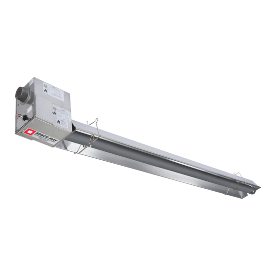
INFRARED RADIANT TUBE HEATER
Single and Two Stage Push Through System (Positive Pressure)
PTS-SS SERIES: (40, 50, 60, 75, 100, 125, 150) N5/L5/N7/L7
PTU-SS SERIES: (40, 50, 60, 75, 100, 125, 150) N5/L5/N7/L7
! INSTALLER: This manual is the property of the owner. Please present this manual to the
owner when you leave the job site.
▲WARNING: Improper installation, adjustment, alteration, service, or maintenance can
cause property damage, injury, or death. Read the installation, operation, and maintenance
instructions thoroughly before installing or servicing this equipment.
IF YOU SMELL GAS:
! DO NOT try to light any appliance.
! DO NOT touch any electrical switch; DO NOT use any
telephone in your building.
! IMMEDIATELY call your gas supplier from a neighbor's
telephone. Follow the gas supplier's instructions. If you
cannot reach your gas supplier, call the fire department.
Scan warranty QR code on the right to
register your product.
!IMPORTANT: SAVE THIS MANUAL FOR FUTURE REFERENCE.
Post Office Box 36485 (28236) • 1700 Parker Drive (28208) • Charlotte, North Carolina
Phone (704) 372-6391 • Fax (704) 332-5843 • www.spaceray.com • email: info@spaceray.com
CAR/TRUCK WASH FACILITIES
Models:
FOR YOUR SAFETY
SPACE-RAY
DO NOT store or use gasoline or other
flammable vapors and liquids in the vicinity of
this or any other appliance.
Form 43155270
July 2023
Advertisement
Table of Contents
Troubleshooting

Related Manuals for Space-Ray PTS-SS Series


Summary of Contents for Space-Ray PTS-SS Series
- Page 1 Single and Two Stage Push Through System (Positive Pressure) Models: PTS-SS SERIES: (40, 50, 60, 75, 100, 125, 150) N5/L5/N7/L7 PTU-SS SERIES: (40, 50, 60, 75, 100, 125, 150) N5/L5/N7/L7 ! INSTALLER: This manual is the property of the owner. Please present this manual to the owner when you leave the job site.
-
Page 2: Table Of Contents
TABLE OF CONTENTS SECTION DESCRIPTION PAGE 1.0) Safety ..............................1 2.0) Installer Responsibility ........................1 3.0) General Information ........................... 1 4.0) Minimum Clearances to Combustibles ................... 3 5.0) Specifications............................4 6.0) Packing List ............................5 6.1) Accessory Packages ........................12 7.0) Typical Layouts –... -
Page 3: Safety
1.0) SAFETY This heater is a self-contained infrared radiant tube heater. Safety information required during installation and operation of this heater is provided in this manual and the labels on the product. The installation, service and maintenance of this heater must be performed by a contractor qualified in the installation and service of gas fired heating equipment. - Page 4 Consult your local fire marshal or insurance company. PTS-SS Series Only: Since straight tube heaters are always hotter at the control end than at the flue terminal end, always observe the minimum recommended mounting heights shown on the specification sheets and in Section 5.0) of this manual.
-
Page 5: Minimum Clearances To Combustibles
NFPA54 requires that the installer must post signs that will “specify the maximum permissible stacking height to maintain the required clearances from the heater to combustibles.” Space-Ray recommends posting these signs adjacent to the heater thermostat or other suitable location that will provide enhanced visibility. -
Page 6: Specifications
14 ft. * MOUNT HEATERS AS HIGH AS POSSIBLE. Minimums are shown as a guideline for human comfort and uniform energy distribution for complete building heating applications. Consult your Space-Ray representative for the particulars of your installation requirements. Model Identification:... -
Page 7: Packing List
6.0) PACKING LIST A. PTS/PTU-SS Burner Package Ref. Part # Each Control Package Includes: Qty. See chart. Burner Box Assembly (Refer to the following chart for Package Part Numbers) 43343332 Installation and Operation Manual -not shown- 42907040 Control Fastener Kit - comprising of: 02189020 Screw, #10 x 1/2”... - Page 8 B. PTS-SS 40-150 Series Body Package Descriptions – ALC Tubes/ Aluminum Reflectors (Package Part Number is indicated on the outside of each corresponding carton.) 10 Ft. 20 Ft. 30 Ft. 40 Ft. 50 Ft. Systems System System System System System PTS-SS Body Packages 10 Ft.
- Page 9 C. PTS-SS 40-150 Series Body Package Descriptions – SS 409 ALC Tubes/ Aluminum Reflectors (Package Part Number is indicated on the outside of each corresponding carton.) 10 Ft. 20 Ft. 30 Ft. 40 Ft. 50 Ft. Systems System System System System System PTS-SS Body Packages...
- Page 10 E. PTS-SS 40-150 Series Body Package Descriptions – SS 409 ALC Tubes/ SS Reflectors (Package Part Number is indicated on the outside of each corresponding carton.) 10 Ft. 20 Ft. 30 Ft. 40 Ft. 50 Ft. Systems System System System System System PTS-SS Body Packages...
- Page 11 U-BEND PACKAGE COMPONENTS: Item 20 – 50Ft. Systems Part No. Description 43208060 43318510 31” Tube Support/Hanger Bracket – SS 42913020 U-Bend 30462981 Tube Coupling – SS 02189020 Screw, Hex Washer Head Self-Drill #10 42873500 U-Bolt - SS 02127120 Hex Nut, 5/16-18 SS 02266010 Speed Clip 43490000 Horizontal U-Bend Reflector 43490050 U-Bend End Reflector...
- Page 12 G. PTU-SS 40-150 Series Body Package Descriptions - SS 409 ALC Tubes/ Aluminum Reflectors (Package Part Number is indicated on the outside of each corresponding carton.) 20 Ft. 30 Ft. 40 Ft. 50 Ft. Systems System System System System PTU-SS Body Packages 20 Ft.
- Page 13 U-BEND PACKAGE COMPONENTS: Item 20 – 50 Ft. Systems Part No. Description 43208062 43318510 31” Tube Support/Hanger Bracket – SS 42913020 U-Bend 30462981 Tube Coupling – SS 02189020 Screw, Hex Washer Head Self-Drill #10 42873500 U-Bolt - SS 02127120 Hex Nut, 5/16-18 SS 02266010 Speed Clip 43490005 Horizontal U-Bend Reflector - SS 43490055 U-Bend End Reflector - SS...
-
Page 14: Accessory Packages
6.1) ACCESSORY PACKAGES A. Elbow Accessory Package, Part #43208010 (Option for PTS Series Only) Contains: Elbow, #43175000……QTY–1 #10-16 x ½ Self-Drilling Screws, #02189020……QTY–2 Tube Coupling, #30462980……QTY–1 B. Corner Reflector Accessory Package, Part #43342000 (Option for PTS Series Only) Contains: Corner Reflector Assembly, #43345000……QTY–1 Speed Clips, #02266010……QTY–4 C. - Page 15 ALC Tube/SS Reflector, Part #43208062 Contains: 31” Tube Support/Hanger Bracket – SS, #43318510…. QTY -1 U-Bend, #42913020……QTY -1 Tube Coupling – SS, #30462981…..QTY – 1 #10-16 x ½ Self-Drilling Screws, #02189020……QTY -8 U-Bolt - SS, #42873500……QTY –2 Hex Nut 5/16 -18 - SS, #02127120….. QTY -4 Speed Clip, #02266010…..QTY –...
- Page 16 PTS-SS Body Extension Packages ALC Tube/Aluminum Reflector Body Packages Optional Extension Packages 10Ft 20Ft 30Ft 40Ft 50Ft 10Ft 20Ft System Length Package Package Package Package Package Extension Extension Extension 44134120 44134220 10’ 44134200 44134120 44134220 44135220 20’ 44135200 44134120 44134220 44135220 30’...
-
Page 17: Typical Layouts - Pts/Ptu Series
7.0) TYPICAL LAYOUTS – PTS/PTU SERIES EMITTER LENGTH BODY LENGTH MODEL MODEL Min. Max. Min. Max. PTS-SS 40 10 Ft. 20 Ft. PTU-SS 40 10 Ft. 10 Ft. PTS-SS 50 20 Ft. 40 Ft. PTU-SS 50 10 Ft. 20 Ft. PTS-SS 60 20 Ft. -
Page 18: Typical Assembly Layout - (Pts Shown)
7.1) TYPICAL ASSEMBLY LAYOUT – (PTS SHOWN) Form 43155270 -16- July 2023... -
Page 19: Dimensions - Pts Series
8.0) DIMENSIONS – PTS SERIES Typical Dimensions Up to 50 Ft. Shown. Form 43155270 July 2023 -17-... -
Page 20: Dimensions - Ptu Series
8.1) DIMENSIONS – PTU SERIES Typical Dimensions Up to 50 Ft. Shown. Form 43155270 -18- July 2023... -
Page 21: Heater Assembly / Joining Of Tube Sections
8.2) HEATER ASSEMBLY / JOINING OF TUBE SECTIONS Form 43155270 July 2023 -19-... - Page 22 Form 43155270 -20- July 2023...
-
Page 23: Typical Suspension Methods
6. Heaters must not be supported by gas or electric supply lines and must be suspended from a permanent structure with adequate load capacity. Space-Ray recommends that the body sections be suspended using chains with turnbuckles. This will allow slight adjustments after assembly and heater expansion/ contraction during operation. -
Page 24: Angle Mounting Of Heaters
Consult your Space-Ray Representative if you have any questions prior to the installation concerning particulars of your application. -
Page 25: Assembly Of Tube Sections
2. Based on the location of the wire hangers and spacing between the suspension points, it might be necessary to use additional reflector retainers to support the reflector system. Please order additional Reflector Retainer (#43980250), Reflector Retainer Spring - SS (#30519040), Hex Washer Head Self-Drill #10 (#02189020), and Speed Clips (#0226010) for each 10 ft. -
Page 26: Assembly Of Extension Section
5. Suspend the chains to attach both wire hangers. Insert the tube into the first wire hanger and then raise the flanged end up to the suspension chain. Use “S” hooks to attach the wire hangers and fasten the wire hanger clamp to the hanger at the flanged end of the tube. - Page 27 Join the tube sections together and secure with tube couplings as described below: The following coupling tightening instructions MUST be followed properly to ensure the integrity of the tube connections. Two #10 self-drilling screws MUST be installed at every coupling as shown in the instructions below.
-
Page 28: Inserting Turbulators
9. Once all the heater body sections are attached, make sure that the heater system is level. If it is not, slight adjustments can be made using the turnbuckles. (See Section 9.0) Important: NEVER reuse a coupling. Always install a new coupling only and torque as per instructions above and the diagrams below. -
Page 29: Adding Body Reflectors
10.3) ADDING BODY REFLECTORS 1. Slide the reflectors through the wire hangers. 2. The tube at the coupling joints must be covered. Slide the reflectors together and provide an overlap of two (2”) inches for each reflector overlap. This will allow for the natural expansion and contraction of the heater when in operation. -
Page 30: Adding Optional 90º Elbow (Pts Only)
11.0) ADDING OPTIONAL 90º ELBOW (PTS ONLY) 1. The optional 90º elbow must be located a minimum of 10 ft. after the burner box. 2. Hang the body sections in a 90º ("L") shaped pattern. Allow spacing for the elbow. The distance from one end of the elbow to the centerline of the opposite leg is 13"... -
Page 31: Adding 180º U-Bend (Ptu Only)
11.2) ADDING 180º U-BEND (PTU ONLY) 1. Hang body sections parallel with each other. The centerline distance from tube at each body section should be 18” as shown. 2. Join tube ends of body sections and the U-Bend together and secure with tube couplings as described in Section 10.1). -
Page 32: Adding Optional U-Bend Reflector (Ptu Only)
11.3) ADDING U-BEND REFLECTOR (PTU ONLY) 1. Place the U-Bend Reflector over the reflectors of each body section with the end resting next to the tube wire hangers as shown. 2. Slide the speed clips on the reflector edges towards the end of the body section reflectors. Two speed clips are required for each side of the U-Bend Reflector. - Page 33 The burner box weighs 38 lbs. Use caution when handling it. Failure to install the burner box in an upright position and lights facing the floor will void the manufacturer’s warranty. Form 43155270 July 2023 -31-...
-
Page 34: Connecting The Tiss System
11.5) CONNECTING THE TISS SYSTEM Description: The TISS (Tube Integrity Safety System) is designed to shut the main burner off in the event that a burnout occurs in the first 10ft. section of the firing tube. Note: When replacing the firing tube, a new TISS wire assembly PN 44176510 (spring and spring retainer clamp not included) must also be installed. - Page 35 3. Hold the spring retainer clamp and pull the TISS wire assembly to end of reflector at overlap joint. Slide spring retainer clamp over end of reflector as shown. Step 3 4. After attachment of the TISS, check to make sure that there is sufficient tension on the wire. Follow the diagram below to increase or decrease the tension as necessary.
- Page 36 ANGLE MOUNTED HEATERS ONLY 5. If heaters are to be angle mounted, the TISS wire holder clamp must first be re-positioned as shown using the bottom hole pattern of the clamp. Follow procedures described earlier for all other adjustments. Step 5 Failure to re-position the wire clamp at the bottom hole pattern will shorten the life expectancy of the TISS wire assembly.
-
Page 37: Gas Connections And Regulations
12.0) GAS CONNECTIONS AND REGULATIONS IMPORTANT BEFORE CONNECTING THE GAS TO THE HEATER 1. Connect to the supply tank or manifold in accordance with the latest edition of National Fuel Gas Code (ANSI Z223.1), and local building codes. Authorities having jurisdiction should be consulted before the installation is made. - Page 38 US ONLY: Connector MUST be installed in “” configuration. Use only the 36” long connector that was furnished with this heater. US ONLY: A gas connector certified for use on a tubular type infrared heater per the standard for Connectors for Gas Appliances, ANSI Z21.24/CSA 6.10 is supplied for installation in US only.
-
Page 39: Instructions For Pressure Test Gauge Connection
13.0) INSTRUCTIONS FOR PRESSURE TEST GAUGE CONNECTION SUPPLY PRESSURE 1. The installer will provide a 1/8” N.P.T. tapped plug, accessible for test gauge connection immediately upstream of the gas supply connection to the heater. OUTLET GAS PRESSURE CHECK AND ADJUSTMENTS Gauges that measure pressure in pounds per square inch are not accurate enough to measure or set the manifold pressure. - Page 40 Figure 1 TO ADJUST REGULATOR (two stage gas valves): Turn on power and energize main gas valve solenoid. Do not energize the HI solenoid. Remove regulator cover screw from the low outlet pressure regulator (see Figure 2 below) and turn screw ...
-
Page 41: Electrical Connections
GAS PRESSURE TABLE SUPPLY PRESSURE MANIFOLD PRESSURE GAS TYPE High Low (2-stage only) Minimum* Maximum Natural Gas 3.5” W.C. 1.4” W.C. 5” W.C. 14” W.C. Propane Gas 10.0” W.C. 4.0” W.C. 11” W.C. 14” W.C. * Minimum permissible gas supply pressure for purpose of input adjustment. 7”... -
Page 42: Single Stage (N5/L5) Internal And Thermostat Connections
14.1) SINGLE STAGE (N5/L5) INTERNAL AND THERMOSTAT CONNECTIONS SINGLE STAGE CONTROLS - INTERNAL CONNECTION WIRING DIAGRAM SINGLE STAGE CONTROLS - SCHEMATIC WIRING IGNITION MODULE TERMINAL DESIGNATIONS DIAGRAM 24VAC/R 24 VAC Supply to Module TH/W Thermostat Input PS/W Pressure Switch Input System Ground Valve Power Valve Ground... - Page 43 SINGLE STAGE CONTROLS - THERMOSTAT WIRING DIAGRAMS SINGLE STAGE CONTROLS G. LINE VOLTAGE (120V) THERMOSTAT CONNECTIONS – SINGLE HEATER Form 43155270 July 2023 -41-...
- Page 44 H. LINE VOLTAGE (120V) THERMOSTAT CONNECTIONS – MULTIPLE HEATERS LOW VOLTAGE (24V) THERMOSTAT CONNECTIONS – SINGLE HEATERS J. LOW VOLTAGE (24V) THERMOSTAT CONNECTIONS – MULTIPLE HEATERS (utilizing a fan center relay) Form 43155270 -42- July 2023...
-
Page 45: Two Stage (N7/L7) Internal And Thermostat Connections
14.2) TWO STAGE (N7/L7) INTERNAL AND THERMOSTAT CONNECTIONS TWO STAGE CONTROLS - INTERNAL CONNECTION WIRING DIAGRAM TWO STAGE CONTROLS - SCHEMATIC WIRING IGNITION MODULE TERMINAL DESIGNATIONS DIAGRAM 24VAC/R 24 VAC Supply to Module TH/W Thermostat Input PS/W Pressure Switch Input System Ground Valve Power Valve Ground... - Page 46 TWO STAGE CONTROLS - THERMOSTAT WIRING DIAGRAMS TWO STAGE CONTROLS A. LOW VOLTAGE (24V) THERMOSTAT CONNECTIONS – SINGLE HEATERS Form 43155270 -44- July 2023...
- Page 47 B. LOW VOLTAGE (24V) THERMOSTAT CONNECTIONS – MULTIPLE HEATERS Form 43155270 July 2023 -45-...
-
Page 48: Venting
C. LOW VOLTAGE (24V) 3 WAY MANUAL SWITCH CONNECTIONS – MULTIPLE HEATERS 15.0) VENTING This is a category lll appliance. A. BASIC FLUE VENTING — Venting must comply with the latest edition of the National Fuel Gas Code (ANSI Z223.1-latest edition) or the authority having jurisdiction. Other venting references are in the equipment volume of the ASHRAE Handbook. - Page 49 Heat Maximum Fresh air Max. combination of Maximum vent length ft. Model exchanger intake length ft (4” fresh air and vent ft. (4” diameter) length ft diameter) (4” diameter) PTS/U-SS 40 PTS/U-SS 40 PTS/U-SS 50,60 PTS/U-SS 50,60 PTS/U-SS 50,60 PTS/U-SS 75 PTS/U-SS 75 PTS/U-SS 75 PTS/U-SS 100...
- Page 50 SINGLE HEATER VENTING (HORIZONTAL THROUGH SIDEWALL) When venting the heater horizontally through a combustible outside sidewall, the same requirements listed previously for venting Vertical Through The Roof apply except as follows: 1. A vent passing through a combustible wall must pass through an approved clearance thimble (Air-Jet #4VT or Ameri-Vent #4EWT or other thimbles) that are listed by a nationally recognized testing agency;...
- Page 51 MULTIPLE HEATER VENTING (CONNECTIONS INTO A COMMON VENT OR MANIFOLD) Requirements for venting of multiple heaters are the same as described for SINGLE HEATER VENTING except as follows: 1. The common vent size and total vent height is normally determined by the number of heaters per common vent, length of horizontal connector runs, and connector fall.
- Page 52 Multiple Heater Vertical Venting Arrangement Multiple Heater Horizontal Venting Arrangement VENT SIZING TABLE — Multiple Heater Venting Number of Heaters Horizontal and vertical Vertical Only PTS/PTU-SS 40 4” 4” 4” 4” PTS/PTU-SS 50 4” 4” 4” 5” PTS/PTU-SS 60 4” 4”...
-
Page 53: Air For Combustion
B. INDIRECT VENTING (UNVENTED HEATERS) — This heater requires ventilation in the building to dilute the products of combustion and provide fresh air for efficient combustion. Where unvented heaters are used, gravity or mechanical means shall be provided to supply and exhaust at least 4 CFM per 1,000 Btu/hr input of installed heaters. - Page 54 In multiple heater applications, the combustion air intake may be ducted individually or common ducted in the same configuration as shown for venting in Section 15.0). For combustion air intake duct sizing, please refer to the Vent Sizing Table and use the diameter indicated, based on the number of heaters per duct. All vent terminations and Combustion Air Intake Terminations must be at least 6”...
-
Page 55: Lighting And Shutdown Instructions
17.0) LIGHTING AND SHUTDOWN INSTRUCTIONS 1. Turn on the gas and electrical supply. 2. Set the thermostat to call for heat. The blower motor will energize. 3. Ignition should occur after the 15-second pre-purge. 4. If the burner fails to light, or flame is not detected during the first trial for ignition (a period of approximately 15 seconds) the gas valve is de-energized and the control goes through an inter-purge delay of approximately 60 seconds before another ignition attempt. - Page 56 Note: When the PTS / PTU is operated by a thermostat interrupting the line voltage (120V) to the heater then the post purge function is disabled. If the flame is not sensed during sequence T3 then the burner will automatically begin re-ignition sequence T2. The ignition sequence will be repeated three times with a 60 second inter-purge.
-
Page 57: Control Component Location
19.0) CONTROL COMPONENT LOCATION Form 43155270 July 2023 -55-... -
Page 58: Cleaning And Annual Maintenance
20.0) CLEANING AND ANNUAL MAINTENANCE This heater must be cleaned and serviced annually by a qualified contractor before the start of each heating season and at any time excessive accumulation of dust and dirt is observed. Maximum heating efficiency and clean combustion will be maintained by keeping the heater clean. -
Page 59: Troubleshooting Guide - Single Stage (N5/L5)
21.0) TROUBLESHOOTING GUIDE – SINGLE STAGE (N5/L5) Form 43155270 July 2023 -57-... - Page 60 TROUBLESHOOTING GUIDE – SINGLE STAGE (CONTINUED) Form 43155270 -58- July 2023...
- Page 61 TROUBLESHOOTING GUIDE – SINGLE STAGE (CONTINUED) Form 43155270 July 2023 -59-...
-
Page 62: Troubleshooting Guide - Two Stage (N7/L7)
21.1) TROUBLESHOOTING GUIDE – TWO STAGE (N7/L7) Form 43155270 -60- July 2023... - Page 63 TROUBLESHOOTING GUIDE – TWO STAGE (CONTINUED) Form 43155270 July 2023 -61-...
- Page 64 TROUBLESHOOTING GUIDE – TWO STAGE (CONTINUED) Form 43155270 -62- July 2023...
-
Page 65: Replacing Parts
22.0) REPLACING PARTS Only use genuine Space-Ray replacement parts. Parts are available from the factory for replacement by a licensed person. Refer to the Replacement Parts Guide in Section 24.0) for all replacement parts. 22.1) REMOVAL OF MAIN BURNER AND ELECTRODES The main burner can be inspected without removing the burner housing from the heat exchanger tube. -
Page 66: Removing Gas Valve And Manifold Assembly
22.2) REMOVING GAS VALVE AND MANIFOLD ASSEMBLY 22.3) AIR SWITCH PRESSURE CHECK Form 43155270 -64- July 2023... -
Page 67: Ignition System Checks
1. Open hinged access panel. 2. Add tubing to connect the air switch tubing P1 + and P2 - with the connector tees and the probes P1+ and P2+. 3. Connect plastic tubing of a digital or inclined water manometer with a 0-2” scale onto the connector tees. 4. -
Page 68: Installation Data
IGNITION MODULE DIAGNOSTICS Flame Fault If at any time the main valve fails to close completely and maintains a flame, the full time flame sense circuit will detect it and energize the combustion blower. Should the main valve later close completely removing the flame signal, the combustion blower will power off following the post purge period. -
Page 69: Replacement Parts Guide
24.0) REPLACEMENT PARTS GUIDE BURNER BOX Item No. Part No. Description Qty. Fasteners 02295040 PHTCS #6-32 x 3/8" 02266010 Speed Clips (for air inlet plate) 02261030 HHTCS #8-32 x 3/8" (green coated) 02242050 PHTCS #8-32 x 3/8" 02242070 PHTCS #8-32 x 1/2” 02123170 RHMS #8-32 x 3/4"... - Page 70 Labels/Manual 42848000 Label, Nameplate – Single Stage 42848110 Label, Nameplate – Two Stage 42013000 Label, Logo (Space-Ray) (Not Shown) 43344070 Label, Clearances to Combustibles 42874120 Label, Wire Connection Diagram – Single Stage 42874130 Label, Wire Connection Diagram – Two Stage...
- Page 71 Form 43155270 July 2023 -69-...
- Page 72 BODY COMPONENTS Item Part No. Description 43980021 Wire Hanger – 30 Deg Angle Mounting - SS 43980151 Wire Hanger Clamp – SS 02200100 Bolt, Round HD SQR Neck 5/16-18 x 4-1/2” - SS 02354000 Nut, Hex Flange HD 5/16-18 SS 43980300 Retainer –...
- Page 73 1) Screws, Nuts and Washers are standard hardware items and can be purchased at any local hardware store. 2) Please order by PART NUMBER – not by Item Number. 3) Replacement Part Prices are available when ordering. 4) Please refer to the complete Model Number when ordering. ALL ILLUSTRATIONS ARE INTENDED TO GIVE THE GENERAL IMPRESSION OF UNITS ONLY.
-
Page 74: Warnings Card
25.0) WARNINGS CARD Copies of this card may be ordered at no charge under part no. 43344990 for installation near the heater. Scan warranty QR code on the right to register your product. Form 43155270 -72- July 2023...
Need help?
Do you have a question about the PTS-SS Series and is the answer not in the manual?
Questions and answers