Table of Contents
Advertisement
Quick Links
INSTALLATION AND OPERATION INSTRUCTIONS
OWNER / INSTALLER:
read and understood before installing, operating or servicing this heater.
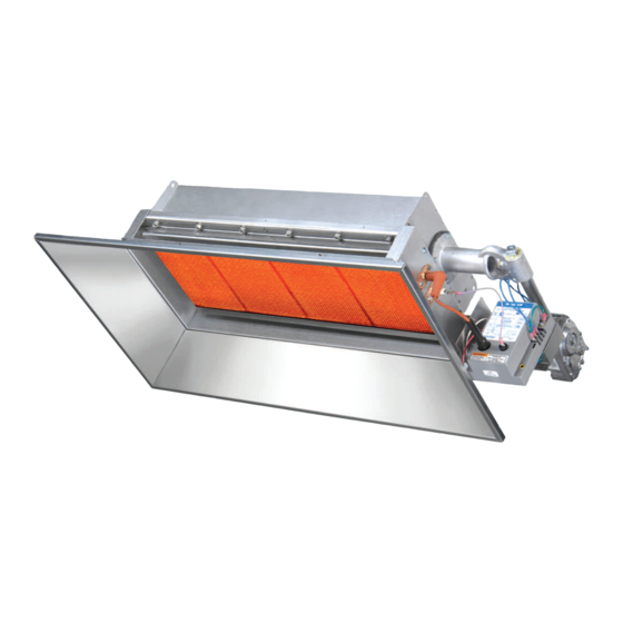
INFRARED RADIANT CERAMIC HEATER
! INSTALLER:
This manual is the property of the owner. Please present this manual
to the owner when you leave the job site.
Improper installation, adjustment, alteration, service, or maintenance can cause
property damage, injury or death. Read the installation, operation and maintenance
instructions thoroughly before installing or servicing this heater.
In locations used for the storage of combustible materials, signs must be posted to
specify the maximum permissible stacking height to maintain the required clearances
from the heater to the combustibles. Signs must either be posted adjacent to the
heater thermostats or in the absence of such thermostats, in a conspicuous location.
NOT FOR RESIDENTIAL USE.
This heater is not approved in any residential application. This includes (but is not
limited to) the home, living quarters, attached garages, etc. Installation in residential
indoor spaces may result in property damage, asphyxiation, and serious injury or
death.
Scan warranty QR code on the right to
register your product.
!IMPORTANT: SAVE THIS MANUAL FOR FUTURE REFERENCE.
Post Office Box 36485
Phone (704) 372-6391 Fax (704) 332-5843 www.spaceray.com email:
For your safety this manual must be carefully and thoroughly
Models: RSCA3, RSCA6, RSCA10
UNVENTED (For Indoor Installation Only)
SPACE-RAY
1700 Parker Drive
(28236)
Charlotte, North Carolina
(28208)
info@spaceray.com
Form #43219000
May 2021
Advertisement
Table of Contents

Related Manuals for Space-Ray RSCA Series


Summary of Contents for Space-Ray RSCA Series
- Page 1 Scan warranty QR code on the right to register your product. !IMPORTANT: SAVE THIS MANUAL FOR FUTURE REFERENCE. SPACE-RAY Post Office Box 36485 1700 Parker Drive Charlotte, North Carolina (28236) (28208) Phone (704) 372-6391 ...
-
Page 2: Table Of Contents
WHAT TO DO IF YOU SMELL GAS: DO NOT try to light any appliance. Extinguish any open flame. Open windows. DO NOT touch any electrical switch. DO NOT use any telephone in your building. Immediately call your gas supplier from a neighbor’s telephone. Follow the gas supplier's instructions. -
Page 3: Safety
SAFETY This heater is a self-contained infrared radiant ceramic heater. Safety information required during installation and operation of this heater is provided in this manual and the labels on the product. The installation, service and maintenance of this heater must be performed by a contractor qualified in the installation and service of gas fired heating equipment. - Page 4 8 feet. Although these heaters may be used in many applications other than space heating (e.g., process heating), Space-Ray will not recognize the warranty for any use other than space heating. Form #43219000...
-
Page 5: Minimum Clearances To Combustibles
This heater is for Indoor Installation only and can be used in Unvented mode. The term Unvented actually means Indirect Vented. While the products of combustion are expelled into the building, national codes require 4 CFM/1000 BTU of heater input ventilation in the building to dilute these products of combustion. This ventilation may be provided by gravity or mechanical means. - Page 6 A critical safety factor to consider before installation is the clearances to combustible materials. Clearance to combustibles is defined as the minimum distance you must have between the infrared surface, or reflector, and the combustible item. Considerations must also be made for moving objects around the infrared heater. The following is a partial list of items to maintain clearances from: Combustible Items Include: Moving Objects Include:...
-
Page 7: Rsca Specifications
1/2" NPT (Female) *MOUNT HEATERS AS HIGH AS POSSIBLE. Minimums are shown as a guideline for human comfort and uniform energy distribution for complete building heating applications. Consult your Space-Ray representative for the particulars of your installation requirements. Form #43219000... -
Page 8: Rsca Dimensions
RSCA DIMENSIONS HANGING The heater can be mounted with the reflector horizontal or angled up to 45º from horizontal. When the heater is to be angle mounted, make sure the gas manifold assembly is on the lower side of the heater. Coil chains (No. 2 or larger) or rigid supports may be used to mount the heater, which must be suspended from a permanent structure with adequate load capacity. -
Page 9: Optional Parabolic Reflector Extension Assembly
OPTIONAL PARABOLIC REFLECTOR EXTENSION ASSEMBLY The heater is completely factory assembled and requires no field assembly. If the optional parabolic reflector extension is utilized, locate and identify the end panels and side panels as shown in the following diagram. Attach the side panels as shown. Attach the end panels so that the end flanges of the end panels overlap the side panels. - Page 10 1. Connect to the supply tank or manifold in accordance with the latest edition of National Fuel Gas Code (ANSI Z223.1), and local building codes. Authorities having jurisdiction should be consulted before the installation is made. 2. All gas supply lines must be located in accordance with the required clearances to combustibles below the heater as listed on the nameplate of the heater.
-
Page 11: Instructions For Pressure Test Gauge Connection
INSTRUCTIONS FOR PRESSURE TEST GAUGE CONNECTION SUPPLY PRESSURE 1. The installer will provide a 1/8" N.P.T. plugged tapping, accessible for test gauge connection immediately upstream of the gas supply connection to the heater. OUTLET GAS PRESSURE CHECK AND ADJUSTMENTS (HONEYWELL 1-STAGE GAS VALVES) 1. - Page 12 OUTLET GAS PRESSURE CHECK AND ADJUSTMENTS (WHITE-RODGERS 1 STAGE) GAS VALVES Gauges that measure pressure in pounds per square inch are not accurate enough to measure or set the manifold pressure. All measurements MUST BE made when the heater and all other gas burning equipment that is connectied to the gas supply system are operating at maximum capacity.
- Page 13 Turn off all electrical power to the system to connect manometer hoses. Turn the pressure test screw in the center of the boss not more than one turn counterclockwise. Attach a 5/16” hose and manometer over the tapered outlet pressure boss on the valve (see figure below). If regulator needs to be adjusted, see instructions below.
-
Page 14: Electrical Connections
ELECTRICAL CONNECTIONS 1. All electric wiring shall conform to the latest edition of the National Electrical Code (ANSI/NFPA No. 70), or the code legally authorized in the locality where the installation is made. 2. The unit must be electrically grounded in accordance with the National Electrical Code (ANSI/NFPA No. 70-latest edition). - Page 15 FIELD CONNECTION AND THERMOSTAT WIRING DIAGRAMS LINE VOLTAGE (120V) THERMOSTAT CONNECTIONS – SINGLE HEATER PER THERMOSTAT B. LINE VOLTAGE (120V) THERMOSTAT CONNECTIONS – MULTIPLE HEATERS PER THERMOSTAT C. LOW VOLTAGE (24V) THERMOSTAT CONNECTIONS – MULTIPLE HEATERS PER THERMOSTAT – (POWER SUPPLIED FROM FAN CENTER RELAY) D.
-
Page 16: Ventilation
E. TYPICAL THERMOSTAT WIRING INSTALLATIONS FOR STANDING PILOT (N1, N1A, L1 OR N1B, L1B CONTROLS) IGNITION SYSTEM VENTILATION Where unvented infrared heaters are used, natural or mechanical means shall be provided to supply and exhaust at least 4 cfm per 1000 Btu per hr input of installed heaters. Exhaust openings for removing flue products shall be above the level of the heaters. -
Page 17: Lighting And Shutdown Instructions
If gravity ventilation is used, the required square feet of inlet and outlet vent area (depending on height and temperature difference) is as follows: RSCA3 = 0.4 s/f RSCA6 = 0.8 s/f RSCA10 = 1.6 s/f The General Ventilation Rules outlined in ASHRAE GUIDE AND DATA BOOK should be observed when locating vents. -
Page 18: Sequence Of Operation
SEQUENCE OF OPERATION The chart below shows the sequence of operation for the normal operating cycle of the heater equipped with direct spark ignition system when connected to a permanent 120V power supply and the heater is turned on and off by a remote 120V thermostat. -
Page 19: 16) Ignition System Checks
a) Lower the heater to the floor or other suitable working surface. b) Remove the reflector from the reflector mounting panels or collar. c) Disconnect the electrode cable and flame sensor cable, or pilot burner tubing. d) Remove the reflector mounting panels from the heater body e) Remove the emitter face from the heater body. -
Page 20: Replacing Parts
TO CHECK FLAME SENSOR CIRCUIT (Fenwal #35-6087D1-038 module only) The flame current is the current that passes through the flame from the sensor to the ground. The minimum flame current necessary to keep the system from lockout is 0.7 micro-amps. a. -
Page 21: Replacement Parts Guide
REPLACEMENT PARTS GUIDE MODELS: RSCA3-(N1, L1, N1B, L1B Item No. Part No. Description 42129000 Plenum Box Assembly 42192000 Emitter Kit (includes items 3 & 4) 40446080 End Gasket (Qty. 2) 40446130 Side Gasket (Qty. 2) 42133000 Screen Retainer (Qty. 2) 40670050 Reverb Screen (Pilot) 40710020... - Page 22 IMPORTANT: Please order by Part Number, not by Item Number. Refer to complete Model Number when ordering. All replacement parts available when ordering. MODEL NUMBER SUFFIXES: N = Natural Gas L = Propane Gas 1 or 1A = Self-Generating (750mv) Standing Pilot with Honeywell Gas Valve = Self-Generating (750mv) Standing Pilot with SIT Gas Valve 5B = Direct Spark Ignition (Fenwal module) with Honeywell Gas Valve 5C = Direct Spark Ignition (Fenwal module) with White-Rodgers Gas Valve...
- Page 23 MODELS: RSCA3-(N5B, L5B, N5C, L5C) Item No. Part No. Description 42129000 Plenum Box Assembly 42192000 Emitter Kit (includes items 3 & 4) 40446080 End Gasket (Qty. 2) 40446130 Side Gasket (Qty. 2) 42133000 Screen Retainer (Qty. 2) 41748030 Reverb Screen 40710020 End Reverb Baffle 40621000...
- Page 24 Form #43219000 May 2021...
- Page 25 MODELS: RSCA6-(N1A, L1, N1B, L1B) Item No. Part No. Description 40714000 Plenum Box Assembly 41218000 Emitter Kit (includes items 3 & 4) 40446080 End Gasket (Qty. 2) 40446090 Side Gasket (Qty. 2) 40608000 Screen Retainer (Qty. 2) 40670030 Reverb Screen (pilot) 40710020 End Reverb Baffle 40621000...
- Page 26 Form #43219000 May 2021...
- Page 27 MODELS: RSCA6-(N5B, L5B, N5C, L5C) Item No. Part No. Description 40714000 Plenum Box Assembly 41218000 Emitter Kit (includes items 3 & 4) 40446080 End Gasket (Qty. 2) 40446090 Side Gasket (Qty. 2) 40608000 Screen Retainer (Qty. 2) 41748010 Reverb Screen 40710020 End Reverb Baffle 40621000...
- Page 28 Form #43219000 May 2021...
- Page 29 MODELS: RSCA10-(N5B, L5B, N5C, L5C) Item No. Part No. Description 40742000 Plenum Box Assembly 41219000 Emitter Kit (includes items 3 & 4) 40446080 End Gasket (Qty. 2) 40446110 Side Gasket (Qty. 2) 40747000 Screen Retainer (Qty. 2) 41748020 Reverb Screen 41156000 Reverb Baffle Assembly (ignition end) 40710020...
- Page 30 Form #43219000 May 2021...
-
Page 31: Warnings Card
WARNINGS CARD This card is furnished with each heater. Additional copies may be ordered under part no. 43344990. Form #43219000 May 2021... - Page 32 LIMITED WARRANTY: Gas-Fired Products, Inc., the manufacturer, warrants to the original owner of any Space-Ray infrared gas heater that said heater will be free from defects in material or workmanship under normal use and service. The heater(s) shall be installed, used and maintained strictly in accordance with the manufacturer's instructions. The manufacturer's sole obligation under this warranty shall be limited to furnishing replacement parts, F.O.B.
Need help?
Do you have a question about the RSCA Series and is the answer not in the manual?
Questions and answers