Table of Contents
Advertisement
Quick Links
INSTALLATION AND OPERATION INSTRUCTIONS
OWNER / INSTALLER: For your safety this manual must be carefully and thoroughly read and
understood before installing, operating or servicing this heater.
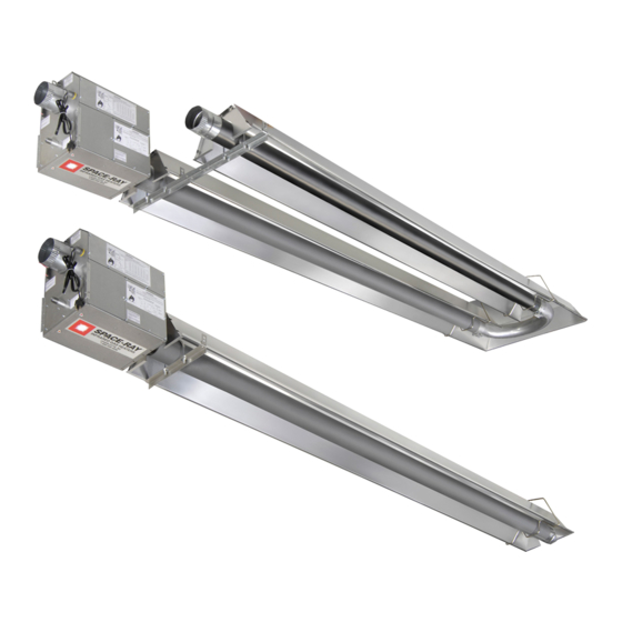
INFRARED RADIANT TUBE HEATER
Two Stage Push Through System (Positive Pressure)
PTS SERIES:
PTU SERIES:
!INSTALLER: This manual is the property of the owner. Please present this manual to the
owner when you leave the job site.
▲WARNING: Improper installation, adjustment, alteration, service, or maintenance can
cause property damage, injury or death. Read the installation, operation and maintenance
instructions thoroughly before installing or servicing this equipment.
IF YOU SMELL GAS:
! DO NOT try to light any appliance.
! DO NOT touch any electrical switch; DO NOT use any
telephone in your building.
! IMMEDIATELY call your gas supplier from a neighbor's
telephone. Follow the gas supplier's instructions. If you
cannot reach your gas supplier, call the fire department.
!IMPORTANT: SAVE THIS MANUAL FOR FUTURE REFERENCE.
Post Office Box 36485 (28236) • 305 Doggett Street (28203) • Charlotte, North Carolina
Phone (704) 372-6391 • Fax (704) 332-5843 • www.spaceray.com • email: info@spaceray.com
Models:
(40, 50, 75, 100, 125, 150, 175, 200) – N7/L7
(40, 50, 75, 100, 125, 150, 175, 200) – N7/L7
FOR YOUR SAFETY
SPACE-RAY
DO NOT store or use gasoline or other
flammable vapors and liquids in the vicinity of
this or any other appliance.
Form #43343530
Mar 09
Advertisement
Table of Contents

Related Manuals for Space-Ray PTS40-N7


Summary of Contents for Space-Ray PTS40-N7
-
Page 1: Installation And Operation Instructions
!IMPORTANT: SAVE THIS MANUAL FOR FUTURE REFERENCE. SPACE-RAY Post Office Box 36485 (28236) • 305 Doggett Street (28203) • Charlotte, North Carolina Phone (704) 372-6391 • Fax (704) 332-5843 • www.spaceray.com • email: info@spaceray.com... -
Page 2: Table Of Contents
TABLE OF CONTENTS SECTION DESCRIPTION PAGE 1.0) Safety ..............................2 2.0) Installer Responsibility ........................2 3.0) General Information........................... 2 4.0) Minimum Clearances to Combustibles................... 4 5.0) Specifications............................5 6.0) Packing List............................5 6.1) Accessory Packages .......................... 9 7.0) Typical Layouts – PTS/PTU Series....................11 7.1) Typical Assembly Layout.........................12 8.0) -
Page 3: Safety
1.0) SAFETY This heater is a self-contained infrared radiant tube heater. Safety information required during installation and operation of this heater is provided in this manual and the labels on the product. The installation, service and maintenance of this heater must be performed by a contractor qualified in the installation and service of gas fired heating equipment. - Page 4 Although these heaters may be used in many applications other than space heating (e.g., process heating), Space-Ray will not recognize the warranty for any use other than space heating. This heater is for Indoor Installation and Covered Patio Installation only and can be used in either Vented or Unvented mode.
-
Page 5: Minimum Clearances To Combustibles
NFPA54 requires that the installer must post signs that will “specify the maximum permissible stacking height to maintain the required clearances from the heater to combustibles.” Space-Ray recommends posting these signs adjacent to the heater thermostat or other suitable location that will provide enhanced visibility. -
Page 6: Specifications
18 ft. 16 ft. * MOUNT HEATERS AS HIGH AS POSSIBLE. Minimums are shown as a guideline for human comfort and uniform energy distribution for complete building heating applications. Consult your Space-Ray representative for the particulars of your installation requirements. Type... - Page 7 BURNER PACKAGE NUMBERS NATURAL GAS PROPANE GAS MODEL NO. PART NO. MODEL NO. PART NO. PTS/U 40/25-N7 ....#44149510 PTS/U 40/25-L7....#44149520 PTS/U 50/30-N7 ....#44149530 PTS/U 50/30-L7....#44149540 PTS/U 75/50-N7 ....#44149550 PTS/U 75/50-L7....#44149560 PTS/U 100/65-N7....#44149570 PTS/U 100/65-L7 ....#44149580 PTS/U 125/80-N7....#44149590 PTS/U 125/80-L7 ....#44149600 PTS/U 150/100-N7 ....
- Page 8 C. PTS 40-200 Series Body Package Descriptions – ALC Option (Aluminized Calorized) (Package Part Number is indicated on the outside of each corresponding carton.) 10Ft. 20Ft. 30Ft. 40Ft. 50Ft. Systems System System System System System PTS Body Packages – Aluminized/ Aluminized or 10 Ft.
- Page 9 Body Fastener Kit (included in body packages) 42907190 42907210 42907210 42907221 42873000 U-Bolt 02127110 Hex Nut, 5/16-18 02189020 HWHSM Screw, #10-16 x ½” TEKS U-Bend Package 43208020 43208020 43208020 43208020 42913020 U-Bend 43318500 31” Tube Support/Hanger Bracket 30462980 Tube Coupling 02189020 HWHSM Screw, #10-16 x ½”...
-
Page 10: Accessory Packages
Body Fastener Kit (included in body packages) 42907190 42907210 42907210 42907221 42873000 U-Bolt 02127110 Hex Nut, 5/16-18 02189020 HWHSM Screw, #10-16 x ½” TEKS U-Bend Package 43208020 43208020 43208020 43208020 42913020 U-Bend 43318500 31” Tube Support/Hanger Bracket 30462980 Tube Coupling 02189020 HWHSM Screw, #10-16 x ½”... - Page 11 C. Corner Reflector Accessory Package, Part #43342000 (Option for PTS Series Only) Contains: Corner Reflector Assembly, #43345000……QTY–1 Speed Clips, #02266010……QTY–4 D. U-Bend Package, Part #43208020 (Option for PTU Series Only) Contains: U-Bend, #42913020……QTY–1 #10-16 x ½ Self-Drilling Screws, #02189020……QTY–2 Tube Coupling, #30462980……QTY–1 31”...
-
Page 12: Typical Layouts - Pts/Ptu Series
7.0) TYPICAL LAYOUTS – PTS/PTU SERIES EMITTER LENGTH BODY LENGTH MODEL MODEL Min. Max. Min. Max. PTS 40/25 10 Ft. 20 Ft. PTU 40/25 10 Ft. 10 Ft. PTS 50/30 20 Ft 40 Ft. PTU 50/30 10 Ft. 20 Ft. PTS 75/50 20 Ft. -
Page 13: Typical Assembly Layout
7.1) TYPICAL ASSEMBLY LAYOUT Form #43343530 -12- Mar 09... -
Page 14: Dimensions - Pts Series
8.0) DIMENSIONS – PTS SERIES Typical Dimensions Up to 60 Ft. Shown. Form #43343530 Mar 09 -13-... -
Page 15: Dimensions - Ptu Series
8.1) DIMENSIONS – PTU SERIES Typical Dimensions Up to 50 Ft. Shown. Form #43343530 -14- Mar 09... -
Page 16: Heater Assembly / Joining Of Tube Sections
8.2) HEATER ASSEMBLY / JOINING OF TUBE SECTIONS Form #43343530 Mar 09 -15-... - Page 17 Form #43343530 -16- Mar 09...
-
Page 18: Typical Suspension Methods
6. Heaters must not be supported by gas or electric supply lines and must be suspended from a permanent structure with adequate load capacity. Space-Ray recommends that the body sections be suspended using chains with turnbuckles. This will allow slight adjustments after assembly and heater expansion/ contraction during operation. -
Page 19: Assembly Of Tube Sections
10.0) ASSEMBLY OF TUBE SECTIONS During field assembly of the heater body sections, the recommended procedure is as follows: 1. Before hanging heater sections, first determine the actual layout of the system (see Sections 7.0) & 8.0) for details). Consideration must also be taken for flue pipe, fresh air ducting, gas piping, clearances to combustibles, etc. -
Page 20: Assembly Of Extension Section
10.1) ASSEMBLY OF EXTENSION SECTION See typical assembly overview (Section 8.0) for typical complete assembly. Assemble additional extension sections as required for all systems. (See Sections 7.0), and 8.0) for typical layout details.) Join the tube sections together and secure with tube couplings as described below: The following coupling tightening instructions MUST be followed properly to ensure the integrity of the tube connections. -
Page 21: Inserting Turbulators
4. Slide the next tube into the coupling. 5. Make sure both tube ends are butted together. 6. Finish tightening both bolts to 40-60 ft.lbs. torque to ensure a complete seal. 7. Use the two Self-drilling screws through the pre-punched holes to secure the tubes in the coupling. 8. -
Page 22: Adding Body Reflectors
MODEL 2 Ft. Turbulator Sections PTS/U 40/25 PTS/U 50/30 PTS/U 75/50 PTS/U 100/65 PTS/U 125/80 PTS/U 150/100 PTS/U 175/110 PTS/U 200/125 10.3) ADDING BODY REFLECTORS 1. Slide the reflectors on the tube support/hanger brackets and through the wire hangers. 2. The tube at the coupling joints must be covered. Slide the reflectors together and provide an overlap of two (2”) inches for the first reflector overlap after the control unit. -
Page 23: Adding Optional 90º Elbow (Pts Only)
11.0) ADDING OPTIONAL 90º ELBOW (PTS ONLY) 1. The optional 90º elbow must be located a minimum of 10 ft. after the burner box. 2. Hang the body sections in a 90º ("L") shaped pattern. Allow spacing for the elbow. The distance from one end of the elbow to the centerline of the opposite leg is 13"... -
Page 24: Adding 180º U-Bend (Ptu Only)
11.2) ADDING 180º U-BEND (PTU ONLY) 1. Hang body sections parallel with each other. The centerline distance from tube at each body section should be 18” as shown. 2. Join tube ends of body sections and the U-Bend together and secure with tube couplings as described in Section 10.1). -
Page 25: Attaching Burner Box Assembly
12.0) ATTACHING BURNER BOX ASSEMBLY 1. Attach the burner box and gasket to end of tube flange and secure with 1/4-20 locknuts. 2. Assemble the optional end reflector flush with the end of the main body reflector. Secure by sliding speed clips onto the reflector edges. -
Page 26: Connecting The Tiss System
12.1) CONNECTING THE TISS SYSTEM Description: The TISS (Tube Integrity Safety System) is designed to shut the main burner off in the event that a burnout occurs in the first 10ft. section of firing tube. Note: When replacing the firing tube a new TISS wire assembly PN 44176010 (spring and spring retainer clamp not included) must also be installed. - Page 27 3. Hold the spring retainer clamp and pull the TISS wire assembly to end of reflector at overlap joint. Slide spring retainer clamp over end of reflector as shown. Step 3 4. After attachment of the TISS, check to make sure that there is sufficient tension on the wire. Follow the diagram below to increase or decrease the tension as necessary.
- Page 28 ANGLE MOUNTED HEATERS ONLY 5. If heaters are to be angle mounted, the TISS wire holder clamp must first be re-positioned as shown using the bottom hole pattern of the clamp. Follow procedures described earlier for all other adjustments. Step 5 Form #43343530 Mar 09 -27-...
-
Page 29: Gas Connections And Regulations
13.0) GAS CONNECTIONS AND REGULATIONS IMPORTANT BEFORE CONNECTING THE GAS TO THE HEATER 1. Connect to the supply tank or manifold in accordance with the latest edition of National Fuel Gas Code (ANSI Z223.1), and local building codes. Authorities having jurisdiction should be consulted before the installation is made. - Page 30 US ONLY: Connector MUST be installed in “⊃” configuration. Use only the 36” long connector that was furnished with this heater. US ONLY: A gas connector certified for use on a tubular type infrared heater per the standard for Connectors for Gas Appliances, ANSI Z21.24/CSA 6.10 is supplied for installation in US only.
-
Page 31: Instructions For Pressure Test Gauge Connection
14.0) INSTRUCTIONS FOR PRESSURE TEST GAUGE CONNECTION SUPPLY PRESSURE 1. The installer will provide a 1/8” N.P.T. tapped plug, accessible for test gauge connection immediately upstream of the gas supply connection to the heater. MANIFOLD PRESSURE – COMBINATION GAS VALVE IS FACTORY SET 1. -
Page 32: Electrical Connections
15.0) ELECTRICAL CONNECTIONS 1. All electric wiring shall conform to the latest edition of the National Electrical Code (ANSI/NFPA No. 70), or the code legally authorized in the locality where the installation is made. 2. The unit must be electrically grounded in accordance with the National Electrical Code (ANSI/NFPA No. 70-latest edition). - Page 33 INTERNAL CONNECTION WIRING DIAGRAM — Direct Spark Ignition Plaque à Tube Integrity bornes Safety System) Schéma de circuit de connexion pressostat Plaque à Robinet bornes à gaz Fusible Moteur d'amorce d'aspiration Transformateur bobine primaire 120ÊV bobine secondaire 24ÊV Haute tension Écartement d'électrode Bloc d'allumage...
- Page 34 FIELD CONNECTION AND THERMOSTAT WIRING DIAGRAMS A. LOW VOLTAGE (24V) THERMOSTAT CONNECTIONS – SINGLE HEATERS B. LOW VOLTAGE (24V) THERMOSTAT CONNECTIONS – MULTIPLE HEATERS Form #43343530 Mar 09 -33-...
-
Page 35: Venting
16.0) VENTING A. BASIC FLUE VENTING — Venting must comply with the latest edition of the National Fuel Gas Code (ANSI Z223.1-latest edition) or the authority having jurisdiction. Other venting references are in the equipment volume of the ASHRAE Handbook. Heat Maximum Fresh air Max. - Page 36 SINGLE HEATER VENTING (VERTICAL THROUGH THE ROOF) 1. When venting the heater to outside of building through a roof, use single-wall metal pipe. This is to be constructed of galvanized sheet metal or other approved noncombustible corrosion-resistant material as allowed by state or local codes. 2.
- Page 37 5. When venting through a sidewall, the horizontal vent pipe shall fall not less than 1/2 inch per 20 feet from the start of the vent system to the vent terminal. All portions of the vent pipe shall be supported to prevent sagging.
- Page 38 Multiple Heater Vertical Venting Arrangement Multiple Heater Horizontal Venting Arrangement VENT SIZING TABLE — Multiple Heater Venting Number of Heaters Horizontal and vertical Vertical Only PTS/PTU 40/25 4” 4” 4” 4” PTS/PTU 50/30 4” 4” 4” 5” PTS/PTU 75/50 4” 4”...
-
Page 39: Air For Combustion
B. INDIRECT VENTING (UNVENTED HEATERS) — This heater requires ventilation in the building to dilute the products of combustion and provide fresh air for efficient combustion. Where unvented heaters are used, gravity or mechanical means shall be provided to supply and exhaust at least 4 CFM per 1,000 Btu/hr input of installed heaters. - Page 40 In multiple heater applications, the combustion air intake may be ducted individually or common ducted in the same configuration as shown for venting in Section 16.0). For combustion air intake duct sizing, please refer to the Vent Sizing Table and use the diameter indicated, based on the number of heaters per duct. (Part No.
-
Page 41: Lighting And Shutdown Instructions
18.0) LIGHTING AND SHUTDOWN INSTRUCTIONS 1. Turn on the gas and electrical supply. Rotate the gas valve knob counter-clockwise to the “ON” position. 2. Set the thermostat to call for heat. The blower motor will energize. 3. Ignition should occur after the 15-second pre-purge. 4. -
Page 42: Sequence Of Operation
19.0) SEQUENCE OF OPERATION The chart below shows the sequence of operation for the normal operating cycle of the PTS/PTU when connected to a permanent 120V power supply and the heater is turned on and off by a remote 24V thermostat. Note: If the flame is not sensed during sequence T3 then the burner will automatically begin re-ignition sequence T2. -
Page 43: Control Component Location
20.0) CONTROL COMPONENT LOCATION Form #43343530 -42- Mar 09... -
Page 44: Cleaning And Annual Maintenance
21.0) CLEANING AND ANNUAL MAINTENANCE This heater must be cleaned and serviced annually by a qualified contractor before the start of each heating season and at any time excessive accumulation of dust and dirt is observed. Maximum heating efficiency and clean combustion will be maintained by keeping the heater clean. -
Page 45: Troubleshooting Guide
22.0) TROUBLESHOOTING GUIDE Form #43343530 -44- Mar 09... - Page 46 Form #43343530 Mar 09 -45-...
- Page 47 Form #43343530 -46- Mar 09...
-
Page 48: Replacing Parts
23.0) REPLACING PARTS Only use genuine Space-Ray replacement parts. Parts are available from the factory for replacement by a licensed person. Refer to the Replacement Parts Guide in Section 25.0) for all replacement parts. 23.1) REMOVAL OF MAIN BURNER AND ELECTRODES The main burner can be inspected without removing the burner housing from the heat exchanger tube. -
Page 49: Removing Gas Valve And Manifold Assembly
23.2) REMOVING GAS VALVE AND MANIFOLD ASSEMBLY 23.3) AIR SWITCH PRESSURE CHECK Form #43343530 -48- Mar 09... -
Page 50: Ignition System Checks
1. Open hinged access panel. 2. Add tubing to connect the air switch tubing P1 + and P2 - with the connector tees and the probes P1+ and P2+. 3. Connect plastic tubing of a digital or inclined water manometer with a 0-2” scale onto the connector tees. 4. -
Page 51: Installation Data
IGNITION MODULE DIAGNOSTICS Flame Fault If at any time the main valve fails to close completely and maintains a flame, the full time flame sense circuit will detect it and energize the combustion blower. Should the main valve later close completely removing the flame signal, the combustion blower will power off following the post purge period. -
Page 52: Replacement Parts Guide
25.0) REPLACEMENT PARTS GUIDE BURNER BOX Item No. Part No. Description Qty. Fasteners 02295040 PHTCS #6-32 x 3/8" 02266010 Speed Clips (for air inlet plate) 02261030 HHTCS #8-32 x 3/8" (green coated) 02242050 PHTCS #8-32 x 3/8" 02242080 PHTCS #8-32 x 1-1/4” 02242070 PHTCS #8-32 x 1/2”... - Page 53 Air Switch (set point @ .65”WC, BLUE LABEL) models 75/50 & 100/65 30186270 Air Switch (set point @ .34”WC, GREEN LABEL) models 125/80 and above Labels/Manual 42848110 Label, Nameplate (Space-Ray) 42013000 Label, Logo (Space-Ray) (Not Shown) 43344070 Label, Clearances to Combustibles 42874030 Label, Wire Connection Diagram 42875000 Label, Warning (installation/configuration/chemical)
- Page 54 Tube Integrity Plaque à Safety Switch) bornes Schéma de circuit de connexion pressostat Plaque à bornes Robinet à gaz Fusible Moteur d'amorce d'aspiration Transformateur bobine primaire 120ÊV bobine secondaire 24ÊV Haute tension Écartement d'électrode Bloc d'allumage 3,2Êmm Vers les autres radiateurs Circuit d'origine Lampes témoins...
- Page 55 ALL ILLUSTRATIONS ARE INTENDED TO GIVE THE GENERAL IMPRESSION OF UNITS ONLY. OTHER COMBINATIONS OF 5 FT. AND 10 FT. SECTIONS, AND ONES WITH OR WITHOUT THE ELBOW PACKAGE ARE POSSIBLE. PLEASE CONSULT WITH YOUR SPACE-RAY SALES REPRESENTATIVE. WE RESERVE THE RIGHT TO ALTER ANY SPECIFICATION WITHOUT NOTICE. Form #43343530...
Need help?
Do you have a question about the PTS40-N7 and is the answer not in the manual?
Questions and answers