Space-Ray LTU Series Installation And Operation Instructions Manual
Ltu/lts series infrared radiant tube heater
Hide thumbs
Also See for LTU Series:
Table of Contents
Advertisement
INSTALLATION AND OPERATION INSTRUCTIONS
OWNER / INSTALLER: For your safety this manual must be carefully and thoroughly read and
understood before installing, operating or servicing this heater.
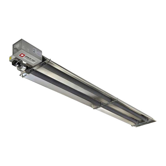
INFRARED RADIANT TUBE HEATER
Single Stage Pull Through System (Negative Pressure)
LTU SERIES:
LTS SERIES:
!INSTALLER: This manual is the property of the owner. Please present this manual to the
owner when you leave the job site.
▲WARNING: Improper installation, adjustment, alteration, service, or maintenance can
cause property damage, injury or death. Read the installation, operation and maintenance
instructions thoroughly before installing or servicing this equipment.
IF YOU SMELL GAS:
! ! ! ! DO NOT
DO NOT try to light any appliance.
DO NOT
DO NOT
! ! ! ! DO NOT
DO NOT touch any electrical switch; DO NOT
DO NOT
DO NOT
telephone in your building.
! ! ! ! IMMEDIATELY
IMMEDIATELY call your gas supplier from a neighbor's
IMMEDIATELY
IMMEDIATELY
telephone. Follow the gas supplier's instructions. If you
cannot reach your gas supplier, call the fire department.
!IMPORTANT: SAVE THIS MANUAL FOR FUTURE REFERENCE.
!IMPORTANT:
!IMPORTANT:
!IMPORTANT:
Post Office Box 36485 (28236) • 305 Doggett Street (28203) • Charlotte, North Carolina
Phone (704) 372-6391 • Fax (704) 332-5843 • www.spaceray.com • email: info@spaceray.com
Models:
(80, 90, 100, 110, 120, 125, 130, 140, 150, 160,
175, 180, 200, 225, 250) – N5/L5
(40, 50, 60, 75, 80, 90, 100, 110, 120, 125, 130,
140, 150, 160, 175, 180, 200, 225, 250) – N5/L5
FOR YOUR SAFETY
FOR YOUR SAFETY
FOR YOUR SAFETY
FOR YOUR SAFETY
DO NOT
DO NOT
DO NOT use any
SAVE THIS MANUAL FOR FUTURE REFERENCE.
SAVE THIS MANUAL FOR FUTURE REFERENCE.
SAVE THIS MANUAL FOR FUTURE REFERENCE.
SPACE- - - - RAY
SPACE
SPACE
SPACE
DO NOT store or use gasoline or other
DO NOT
store or use gasoline or other
DO NOT
DO NOT
store or use gasoline or other
store or use gasoline or other
flammable vapors and liquids in the vicinity of
flammable vapors and liquids in
flammable vapors and liquids in
flammable vapors and liquids in
this or any other appliance.
this or any other appliance.
this or any other appliance.
this or any other appliance.
RAY
RAY
RAY
the vicinity of
the vicinity of
the vicinity of
Form #43155010
Sept 2011
Advertisement
Table of Contents

Related Manuals for Space-Ray LTU Series


Summary of Contents for Space-Ray LTU Series
-
Page 1: Installation And Operation Instructions
INFRARED RADIANT TUBE HEATER Single Stage Pull Through System (Negative Pressure) Models: LTU SERIES: (80, 90, 100, 110, 120, 125, 130, 140, 150, 160, 175, 180, 200, 225, 250) – N5/L5 LTS SERIES: (40, 50, 60, 75, 80, 90, 100, 110, 120, 125, 130, 140, 150, 160, 175, 180, 200, 225, 250) –... -
Page 2: Table Of Contents
LTU 80-175 Series Heater Assembly Overview ................10 8.3) LTU 180-250 Series Heater Assembly Overview ................. 11 8.4) LTU Series 15’ Body Package Opening ..................11 8.5) LTU 80-130 Series Heater Assembly .................... 12 8.6) LTU 125-250 Series – Joining of 5’ and 10’ Body Sections ............15 9.0) -
Page 3: Safety
1.0) SAFETY This heater is a self-contained infrared radiant tube heater. Safety information required during installation and operation of this heater is provided in this manual and the labels on the product. The installation, service and maintenance of this heater must be performed by a contractor qualified in the installation and service of gas fired heating equipment. - Page 4 Although these heaters may be used in many applications other than space heating (e.g., process heating), Space-Ray will not recognize the warranty for any use other than space heating. This heater is for Indoor Installation and Covered Patio Installation only and can be used in either Vented or Unvented mode.
-
Page 5: Minimum Clearances To Combustibles
4.0) MINIMUM CLEARANCES TO COMBUSTIBLES Minimum clearances to combustibles shall be measured from the outer surfaces as shown in the following diagram: Horizontal 45° Angle (Maximum) MINIMUM CLEARANCES TO COMBUSTIBLES MINIMUM CLEARANCES TO COMBUSTIBLES MINIMUM CLEARANCES TO COMBUSTIBLES MINIMUM CLEARANCES TO COMBUSTIBLES Angle Mounted at Angle Mounted at Angle Mounted at... -
Page 6: Typical Suspension Methods
6. Heaters must not be supported by gas or electric supply lines and must be suspended from a permanent structure with adequate load capacity. Space-Ray recommends that the body sections be suspended using chains with turnbuckles. This will allow slight adjustments after assembly and heater expansion/ contraction during operation. -
Page 7: Ltu Series Specifications
20 ft. 19 ft. * MOUNT HEATERS AS HIGH AS POSSIBLE. Minimums are shown as a guideline for human comfort and uniform energy distribution for complete building heating applications. Consult your Space-Ray representative for the particulars of your installation requirements. Type... - Page 8 LTU 80- - - - 250 LTU 80 250 CONTROL/DRAFT INDUCER CONTROL/DRAFT INDUCER PACKAGE NUMB PACKAGE NUMBERS LTU 80 LTU 80 CONTROL/DRAFT INDUCER CONTROL/DRAFT INDUCER PACKAGE NUMB PACKAGE NUMB NATURAL GAS NATURAL GAS PROPANE GAS PROPANE GAS NATURAL GAS NATURAL GAS PROPANE GAS PROPANE GAS MODEL NO.
-
Page 9: Ltu Series Typical Layouts
8.0) LTU SERIES TYPICAL LAYOUTS EMITTER EMITTER EMITTER EMITTER MODEL MODEL MODEL MODEL LENGTH LENGTH LENGTH LENGTH 30’ LTU 80, 90, 100, 110, 120, 125, 130 LEGEND 40’ LTU 125, 130, 140, 150, 160, 175 50’ LTU 180, 200, 225, 250... - Page 10 Models: Models: LTU LTU 180 180- - - - 2 2 2 2 5 5 5 5 0 0 0 0 Models: Models: Form #43155010 Sept 2011...
-
Page 11: Ltu 80-175 Series Heater Assembly Overview
8.2) LTU 80-175 SERIES HEATER ASSEMBLY OVERVIEW Form #43155010 -10- Sept 2011... -
Page 12: Ltu 180-250 Series Heater Assembly Overview
Models: Models: 8.4) LTU SERIES 15’ BODY PACKAGE OPENING Follow the procedure below to open the 15’ body package. 1. Remove end reflectors from packaging. 2. Lift the tube at the flange end, then slide tube support/hanger bracket between marks on tubes and tighten the “U”... -
Page 13: Ltu 80-130 Series Heater Assembly
8.5) LTU 80-130 SERIES HEATER ASSEMBLY During field assembly of the heater, the recommended procedure is as follows: 1. Install the suspension (according to Section 8.1) using proper suspension method (see Section 5.0). Trapeze Method Trapeze Method Trapeze Method Trapeze Method Individual Suspension Method Individual Suspension Method Individual Suspension Method... - Page 14 3. Assembly the reflectors onto the body section. Leave 3” space between the tube flange and the first reflector for later mounting of control box and draft inducer. 4. Place the flanges of the control end reflector flush with the end of the first reflector. Secure by sliding speed clips onto reflector edges.
- Page 15 7. Insert SJO cable through the strain relief bushing of the control box and connect to L1 and L2 of terminal block. Refer also to the wiring diagram in Section16.0). 8. Reflectors should overlap 1” to 3” and must be secured by sliding speed clips on the reflector edges. One speed clip is required for each side of the reflector.
-
Page 16: Ltu 125-250 Series - Joining Of 5' And 10' Body Sections
DETAIL “A” DETAIL “B” Reflector Clamp Installation 8.6) LTU 125-250 SERIES – JOINING OF 5’ AND 10’ BODY SECTIONS These models require the use of an additional 5’ body section for LTU 125-175 and 10’ body section for LTU 180- 250, as shown in Section 8.1). -
Page 17: Lts Series Specifications
20 ft. 19 ft. * MOUNT HEATERS AS HIGH AS POSSIBLE. Minimums are shown as a guideline for human comfort and uniform energy distribution for complete building heating applications. Consult your Space-Ray representative for the particulars of your installation requirements. Type... - Page 18 LTS SERIES LTS SERIES CONTROL/DRAFT INDUCER CONTROL/DRAFT INDUCER PACKAGE NUMBERS PACKAGE NUMBERS LTS SERIES LTS SERIES CONTROL/DRAFT INDUCER CONTROL/DRAFT INDUCER PACKAGE NUMBERS PACKAGE NUMBERS NATURAL GAS NATURAL GAS NATURAL GAS NATURAL GAS PROPA PROPANE GAS PROPA PROPA NE GAS NE GAS NE GAS MODEL NO.
- Page 19 C. C. C. C. LTS LTS 225 225- - - - 2 2 2 2 50 Body Package Descriptions 50 Body Package Descriptions 50 Body Package Descriptions 50 Body Package Descriptions (Package Part Number is indicated on the outside of each corresponding carton.) 10’...
-
Page 20: Lts Series Typical Layouts
11.0) LTS SERIES TYPICAL LAYOUTS LEGEND NOTES: NOTES: NOTES: NOTES: 1. In all configurations, the control unit must be connected directly to either a) the 24-hole flange of the 10 ft. aluminized steel start/end body section (for LTS 40-200 models) or b) the 6-hole flange of the 10 ft. alumi- therm steel starting body section (for LTS 225 and 250 models). -
Page 21: Lts Series Dimensions
11.1) LTS SERIES DIMENSIONS Typical Dimensions Up to 50 Ft. Shown Form #43155010 -20- Sept 2011... -
Page 22: Lts 40-175 Series Heater Assembly Overview
11.2) LTS 40-175 SERIES HEATER ASSEMBLY OVERVIEW Form #43155010 Sept 2011 -21-... -
Page 23: Lts 180-250 Series Heater Assembly Overview
11.3) LTS 180-250 SERIES HEATER ASSEMBLY OVERVIEW Models: Models: Models: Models: LTS LTS 180 180- - - - 2 2 2 2 0 0 0 0 0 0 0 0 Models: LTS 225 Models: LTS 225 Models: LTS 225 Models: LTS 225- - - - 250 11.4) LTS SERIES HEATER ASSEMBLY During field assembly of the LTS series heater body sections, the recommended procedure is as follows:... - Page 24 4. Join the body sections together and secure with tube couplings as follows: T T T T he following he following he following coupling he following coupling coupling coupling tightening instructions MUST tightening instructions MUST tightening instructions MUST tightening instructions MUST be be be followed followed...
- Page 25 5. For LT For LTS225 S225- - - - 250 Models 250 Models, join the first two body sections as illustrated below. For LT For LT S225 S225 250 Models 250 Models a) Join the tube flanges of the body sections together with the gasket in between. Loosely attach the heater body sections together with the ¼-20 screws and locknuts provided.
- Page 26 6. Assemble reflectors onto the body section. Reflectors should overlap 1” to 2” and must be secured by sliding speed clips on the reflector edges. One speed clip is required for each side of the reflector. 7. Fasten the first reflector to the tube support/hanger bracket with (2) #10 sheet metal screws according to Detail “A”.
-
Page 27: Lts Series - Adding Optional 90º Elbow
11.5) LTS SERIES - ADDING OPTIONAL 90º ELBOW 1. The optional 90º elbow must be located a minimum of 10 ft. after the control box. 2. Hang the body sections in a 90º ("L") shaped pattern. Allow spacing for the elbow. The distance from one end of the elbow to the centerline of the opposite leg is 13"... -
Page 28: Lts Series - Attaching Draft Inducer Assembly
4. The heater can be mounted horizontally horizontally or at an angle of up to 45 degrees 45 degrees maximum from horizontal. When horizontally horizontally 45 degrees 45 degrees angle mounting, the control box control box control box must be positioned upright control box upright upright. -
Page 29: Lts Series - Inclined Mounting Instructions
11.9) LTS SERIES - INCLINED MOUNTING INSTRUCTIONS These inclined mounting instructions relate to LTS series heaters (straight tubes) that do not utilize the elbow accessory. These heaters have been tested and design certified by the CSA for 2”/12” pitch (10º) inclined mounting of the heater from the control box to the draft inducer assembly as shown in the following diagram. - Page 30 The purpose of this type mounting is to allow the heater to be mounted in the plane of the roof (particularly in modern “Butler” type buildings frequently used today). This will typically put the heater out of the way while still providing the warmth and comfort.
-
Page 31: Accessory Packages
12.0) ACCESSORY PACKAGES A. A. A. A. Elbow Accessory Package, P Elbow Accessory Package, P Elbow Accessory Package, P Elbow Accessory Package, Part #43208010 art #43208010 art #43208010 art #43208010 (Option for LTS Series Only) Contains: Elbow, #43175000……QTY–1 #10-16 x ½ Self-Drilling Screws, #02189020……QTY–2 Tube Coupling, #30462980……QTY–1 B. - Page 32 5. Horizontal and 45º draft inducer positions can allow the plastic vacuum air tube to sag. The air tube should be shortened to prevent a downward sag that could allow condensation build-up in the tube. Hoizontal Mounting Horizontal Mounting LTU Series LTS Series 45 Deg. Angle Mounting LTS Series 40 Deg.
-
Page 33: Gas Connections And Regulations
14.0) GAS CONNECTIONS AND REGULATIONS IMPORTANT BEFORE CONNECTING THE GAS TO THE HEATER IMPORTANT BEFORE CONNECTING THE GAS TO THE HEATER IMPORTANT BEFORE CONNECTING THE GAS TO THE HEATER IMPORTANT BEFORE CONNECTING THE GAS TO THE HEATER 1. Connect to the supply tank or manifold in accordance with the latest edition of National Fuel Gas Code (ANSI Z223.1), and local building codes. - Page 34 INCORRECT POSITIONS WRONG WRONG WRONG WRONG US ONLY: US ONLY: Connector MUST be installed in “ Connector MUST be installed in “⊃ ⊃ ⊃ ⊃ ” configuration. Use only ” configuration. Use only US ONLY: US ONLY: Connector MUST be installed in “ Connector MUST be installed in “...
-
Page 35: Instructions For Pressure Test Gauge Connection
15.0) INSTRUCTIONS FOR PRESSURE TEST GAUGE CONNECTION SUPPLY PRESSURE SUPPLY PRESSURE SUPPLY PRESSURE SUPPLY PRESSURE 1. The installer will provide a 1/8” N.P.T. tapped plug, accessible for test gauge connection immediately upstream of the gas supply connection to the heater. MANIFOLD PRESSURE MANIFOLD PRESSURE MANIFOLD PRESSURE... -
Page 36: Electrical Connections
16.0) ELECTRICAL CONNECTIONS ELECTRIC SHOCK HAZARD 1. All electric wiring shall conform to the latest edition of the National Electrical Code (ANSI/NFPA No. 70), or the code legally authorized in the locality where the installation is made. 2. The unit must be electrically grounded in accordance with the National Electrical Code (ANSI/NFPA No. 70-latest edition). - Page 37 INTERNAL CONNECTION WIRING DIAGRAM INTERNAL CONNECTION WIRING DIAGRAM INTERNAL CONNECTION WIRING DIAGRAM INTERNAL CONNECTION WIRING DIAGRAM — — — — Direct Spark Ignition Direct Spark Ignition Direct Spark Ignition Direct Spark Ignition Circuit d'origine Lampes témoins Moteur Connexions client d'amorce d'aspiration Bloc de jonction Armoire de commande...
- Page 38 FIELD CONNECTION FIELD CONNECTION FIELD CONNECTION FIELD CONNECTION AND THERMOSTAT AND THERMOSTAT AND THERMOSTAT WIRING DIAGRAMS AND THERMOSTAT WIRING DIAGRAMS WIRING DIAGRAMS WIRING DIAGRAMS A. A. A. A. LINE VOLTAGE (120V) THERMOSTAT CONNEC LINE VOLTAGE (120V) THERMOSTAT CONNEC LINE VOLTAGE (120V) THERMOSTAT CONNEC LINE VOLTAGE (120V) THERMOSTAT CONNECTIONS TIONS TIONS –...
- Page 39 C. C. C. C. LOW LOW VOLTAGE ( VOLTAGE ( VOLTAGE ( VOLTAGE (24 24V) THERMOSTAT CONNECTIONS V) THERMOSTAT CONNECTIONS V) THERMOSTAT CONNECTIONS V) THERMOSTAT CONNECTIONS – – – – SINGLE HEATER PER THERMOSTAT SINGLE HEATER PER THERMOSTAT SINGLE HEATER PER THERMOSTAT SINGLE HEATER PER THERMOSTAT FUSE 2A Order 24V Relay Kit (Part No.
-
Page 40: Venting
17.0) VENTING CARBON MONOXIDE HAZARD A. A. A. A. BASIC FLUE VENTING BASIC FLUE VENTING BASIC FLUE VENTING BASIC FLUE VENTING — Venting must comply with the latest edition of the National Fuel Gas Code (ANSI Z223.1-latest edition) or the authority having jurisdiction. Other venting references are in the equipment volume of the ASHRAE Handbook. - Page 41 SINGLE HEATER VENTING SINGLE HEATER VENTING SINGLE HEATER VENTING SINGLE HEATER VENTING (HORIZONTAL THROUGH SIDEWALL) (HORIZONTAL THROUGH SIDEWALL) (HORIZONTAL THROUGH SIDEWALL) (HORIZONTAL THROUGH SIDEWALL) When venting the heater horizontally through a combustible outside sidewall, the same requirements listed previously for venting Vertical Through The Roof Vertical Through The Roof Vertical Through The Roof apply except as follows: Vertical Through The Roof...
- Page 42 MULTIPLE HEATER VENTING MULTIPLE HEATER VENTING (CONNECTIONS INTO A COMMON VENT OR MANIFOLD) (CONNECTIONS INTO A COMMON VENT OR MANIFOLD) MULTIPLE HEATER VENTING MULTIPLE HEATER VENTING (CONNECTIONS INTO A COMMON VENT OR MANIFOLD) (CONNECTIONS INTO A COMMON VENT OR MANIFOLD) Requirements for venting of multiple heaters are the same as described for SINGLE HEATER VENTING SINGLE HEATER VENTING except as SINGLE HEATER VENTING...
- Page 43 Multiple Heater Horizontal Venting Arrangement Multiple Heater Venting (Connections into a Manifold) VENT SIZING VENT SIZING TABLE VENT SIZING VENT SIZING TABLE TABLE TABLE — — — — Multiple Heater Venting Multiple Heater Venting Multiple Heater Venting Multiple Heater Venting Number of Heaters Number of Heaters Number of Heaters...
-
Page 44: Air For Combustion
B. B. B. B. INDIRECT VENTING INDIRECT VENTING (UNVENTED HEATERS) — This heater requires ventilation in the building to dilute the (UNVENTED HEATERS) INDIRECT VENTING INDIRECT VENTING (UNVENTED HEATERS) (UNVENTED HEATERS) products of combustion and provide fresh air for efficient combustion. Where unvented heaters are used, gravity or mechanical means shall be provided to supply and exhaust at least 4 CFM per 1,000 Btu/hr input of installed heaters. - Page 45 In multiple heater applications multiple heater applications, the combustion air intake may be ducted individually or common ducted in the multiple heater applications multiple heater applications same configuration as shown for venting in Section 17.0). For combustion air intake duct sizing, please refer to the Vent Sizing Table Vent Sizing Table and use the diameter indicated, based on the number of heaters per duct.
-
Page 46: Lighting And Shutdown Instructions
19.0) LIGHTING AND SHUTDOWN INSTRUCTIONS 1. Turn on the gas and electrical supply. Rotate the gas valve knob counter-clockwise to the “ON” position. 2. Set the thermostat to call for heat. The blower motor will energize. 3. Ignition should occur after the 30-second air pre-purge. 4. -
Page 47: Control Component Location
21.0) CONTROL COMPONENT LOCATION NOTE: NOTE: NOTE: NOTE: Access panel only opens to 90 Access panel only opens to 90 Access panel only opens to 90 Access panel only opens to 90° ° ° ° ..Form #43155010 -46- Sept 2011... -
Page 48: Cleaning And Annual Maintenance
22.0) CLEANING AND ANNUAL MAINTENANCE ELECTRIC SHOCK & EXPLOSION HAZARD This heater must be cleaned and serviced annually by a qualified contractor before the start of each heating season and at any time excessive accumulation of dust and dirt is observed. Maximum heating efficiency and clean combustion will be maintained by keeping the heater clean. -
Page 49: Troubleshooting Guide
23.0) TROUBLESHOOTING GUIDE Form #43155010 -48- Sept 2011... - Page 50 Form #43155010 Sept 2011 -49-...
- Page 51 Form #43155010 -50- Sept 2011...
-
Page 52: Replacing Parts
24.0) REPLACING PARTS ELECTRIC SHOCK & EXPLOSION HAZARD Only use genuine Space-Ray replacement parts. Parts are available from the factory for replacement by a licensed person. Refer to the Replacement Parts Guide in Section 26.0) for all replacement parts. 24.1) REMOVING SPARK ELECTRODE The main burner can be inspected without removing the burner housing from the heat exchanger tube. -
Page 53: Removing Main Burner And Gas Valve
24.2) REMOVING MAIN BURNER AND GAS VALVE 1. Disconnect electrical supply and gas connection at the restrainer nipple. 2. Open the access panel and disconnect the wires from gas valve. 3. Remove the burner clamp and screws. 4. Remove the burner and gas valve assembly from the cabinet. 5. -
Page 54: Air Switch Pressure Check
24.3) AIR SWITCH PRESSURE CHECK 0.37” WC 1. Open hinged access panel. 2. Add tubing to connect the air switch with the connector tee and the existing tubing. 3. Connect plastic tubing of a digital or inclined water manometer with a 0-2” scale onto the connector tees. 4. -
Page 55: Motor And Blower Wheel Check
IGNITION MODULE DIAGNO IGNITION MODULE DIAGNOSTICS STICS IGNITION MODULE DIAGNO IGNITION MODULE DIAGNO STICS STICS (Fenwal #35- - - - 6087J1 (Fenwal #35 6087J1- - - - 034 module only) 034 module only) (Fenwal #35 (Fenwal #35 6087J1 6087J1 034 module only) 034 module only) The LED LED located on the ignition module will flash ON... -
Page 56: Replacement Parts Guide
26.0) REPLACEMENT PARTS GUIDE DRAFT INDUCER COMPONENTS DRAFT INDUCER COMPONENTS DRAFT INDUCER COMPONENTS DRAFT INDUCER COMPONENTS Item No. Item No. Item No. Item No. Part No. Part No. Part No. Part No. Description Description Description Description 42917000 Draft Inducer Assembly, 40M–175M Btu/hr models 42928000 Motor Replacement Kit, 40M–175M Btu/hr models 42917010... - Page 57 Circuit d'origine Schéma de circuit de connexion Connexions client Moteur Lampes témoins d'amorce d'aspiration Bloc de jonction Armoire de commande pressostat Robinet à gaz Fusible Écartement ENGLISH FRANCAIS d'électrode 4,7Êmm Haute tension Plaque à Câble SJO bornes Transformateur (non compris) bobine primaire 120ÊV Vers les autres bobine secondaire 24ÊV...
- Page 58 Label, Wire Diagram (ladder) 42874000 Label, Wire Diagram 42875000 Label, Warning 43269000 Label, 24V Supply 43270000 Label, Terminal ID 42013000 Label, “Space-Ray” Logo 42848000 Label, “Space-Ray” Nameplate 43344000 Label, Clearance to Combustibles 43344050 Label, Gas Connector Warning Form #43155010 Sept 2011 -57-...
- Page 59 24 VOLT SUPPLY ONLY! TERMINAL “1” “2” Moteur Témoin vert Transformateur 24ÊV Témoin rouge pressostat Bloc d'allumage électrode Robinet à gaz Témoin ambre Montage horizontal (69cm) (15cm) (104cm) (76cm) (122cm) (30cm) WARNING: AVERTISSEMENT: WARNING: (69cm) (15cm) (145cm) (76cm) (122cm) (30cm) (132cm) (15cm) (145cm)
- Page 60 BODY BODY COMPONENTS BODY BODY COMPONENTS COMPONENTS COMPONENTS: : : : LTS LTS 40 40- - - - 250 Item Item Item Item Part No. Part No. Part No. Part No. Description Description Description Description 02266010 Reflector Speed Clip 42769011 Reflector Clamp with Screw 42873000 “U”...
- Page 61 ALL ILLUSTRATIONS ARE INTENDED TO GIVE THE GENERAL IMPRESSION OF UNITS ONLY. OTHER COMBINATIONS OF 5 FT. AND 10 FT. SECTIONS, AND ONES WITH OR WITHOUT THE ELBOW PACKAGE ARE POSSIBLE. PLEASE CONSULT WITH YOUR SPACE-RAY SALES REPRESENTATIVE. WE RESERVE THE RIGHT TO ALTER ANY SPECIFICATION WITHOUT NOTICE.
Need help?
Do you have a question about the LTU Series and is the answer not in the manual?
Questions and answers