Daikin Clima-Flex CLIC Series Installation, Operation And Maintenance Manual
Air-cooled scroll compressor chiller water generator unit, refrigerant hfc-410a or 454b 50/60 hz
Hide thumbs
Also See for Clima-Flex CLIC Series:
- Control manual (30 pages) ,
- Control manual (30 pages)
Table of Contents

Subscribe to Our Youtube Channel
Related Manuals for Daikin Clima-Flex CLIC Series


Summary of Contents for Daikin Clima-Flex CLIC Series
- Page 1 Installation, Operation and Maintenance Manual Group: Chiller Part Number: IOM CLIC Date: 28 November 2023 CLIC Series Air-Cooled Scroll Compressor Chiller Water Generator Unit Model 25 to 250 RT Refrigerant HFC-410A or 454B 50/60 Hz...
-
Page 2: Table Of Contents
Table of Contents Safety Warning...............4 General Description ............5 Features / Benefits............6 Installation and Application Information....8 Refrigeration Schematics..........18 Dimensions and Weights - Single Unit......21 Vacuum / Refrigerant Charge........32 Drop Data...............35 Electrical Data............36 R454B Electrical Data..........49 Unit Controller Operation........58 Sequence Of Operation..........63 Unit Functions..............65 Alarms................68 Controller Use............70... - Page 3 Pre-Start Checklist - Scroll Compressor Chillers Must be completed, signed, and provided to Clima Flex at least 2 weeks prior to requested start date. Job Name Installation Location Customer Order Number Model Number(s) G.O. Number(s) Chilled Water and Condenser Water for Water-cooled Chiller Initials Piping Complete Water strainer(s) installed in piping per manual requirements...
-
Page 4: Safety Warning
Safety Warning This manual contains safety instructions that must be followed during installation and maintenance of the unit. Read this manual before installing or operating this unit. NOTE: Installation and maintenance should be performed only by qualified personnel who are familiar with local codes and regulations and who have experience with this type of equipment. -
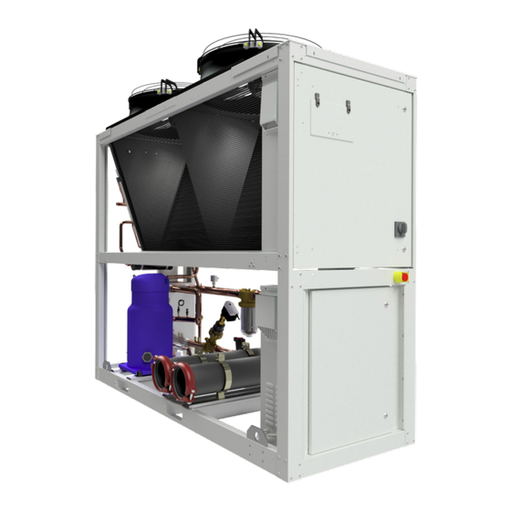
Page 5: General Description
General Description Clima Flex’s CLIC Series air-cooled chilled water generators are The electrical control center includes all operating controls and self-contained, complete, automatic chillers designed for outdoor equipment protection necessary for reliable automatic operation. installation. The package units are fully assembled, factory wired, Components housed in a weatherproof control panel. -
Page 6: Features / Benefits
Features / Benefits EFFICIENCY DESIGN Our units are designed to meet the needs of any project. Research conducted by the Engineering Department has resulted Our intelligent process controllers and smart temperature sensors in units with high design efficiency and optimum performance. The selection of the main components, our quality and control provide maximum performance and energy savings. - Page 7 Features and Benefits TESTING Ideal applications for Insitu® spray-applied coatings. Each unit is pressure and vacuum tested and then charged with the refrigerant required for proper operation based on the • Mini-splits customer’s installation conditions. • Packaged enclosures • Condensing units The units are evaluated at full load operation with water flow, heat •...
-
Page 8: Installation And Application Information
Installation and Application Information OPERATING AND STANDBY LIMITS Table unit CLIC Table 1. Maximum standby ambient temperature 130°F (54°C) Maximum operating ambient temperature 113°F (45°C) Minimum operating ambient temperature (standard control) 55°F(12°) Outgoing chilled water temperature 40°F to 65°F (4°C to 18°C) Outgoing chilled fluid temperatures (with antifreeze) - Note that in cases of high ambient tempera- ture, the lowest outgoing water temperature settings may be outside the chiller’s operating enve- 15°F to 65°F (-9°C to... - Page 9 Installation and Application Information Figure 1. Required elevation arrangement. PLACEMENT OF THE UNIT CLIC series units are for outdoor applications and can be mounted on the roof or on the ground. For roof mounted applications, install the unit on a steel channel or I-beam frame to support the unit above the roof. The use of spring isolators is recommended for roof applications.
- Page 10 Installation and Application Information MOUNTING The inside of the base rail is open to allow access to secure mounting bolts, etc. Mounting location dimensions are indicated on the dimensional drawing beginning on page 21 . All compressor bolts, rubber, grommets and fasteners should be left in place in the base. None of these fasteners are considered “temporary shipping bolts”.
- Page 11 Installation and Application Information CLEANING SERVICE CAUTION A. The control panels are located at the end of the chiller and require a minimum clearance of 1.2 meters in front of the The performance of the unit may be affected if the operating panels.
- Page 12 Installation and Application Information Pit installation Figure 4. Two units side by side Case 5. Pit installations can cause operating problems due to recirculation and air restriction and require that sufficient air separation be provided, safety requirements be met, and service access be provided.
- Page 13 Installation and Application Information piping, respectively, (see Figure 7) These evaporators do not have drain or vent connections due to their construction. WARNING Purge air from the water system prior to unit start-up to provide adequate flow through the evaporator. Polyolester oil, commonly known as POE oil, is a synthetic •...
- Page 14 Installation and Application Information INLET STRAINER GUIDELINES The minimum flow rate and pressure drop are based on a full load evaporator temperature drop of 16°F. Evaporator flow rates below the minimum values may result in laminar flow leading to An inlet water filter kit must be installed in the cold water piping low pressure alarms, fouling and poor temperature control (See upstream of the evaporator inlet.
- Page 15 Installation and Application Information FLOW SWITCH Evaporator freeze protection Evaporator freezing can be a problem in the application of air- All chillers require a chilled water flow switch to verify that there cooled water chillers in sub-zero temperature areas. To protect is adequate water flow through the evaporator and to shut down against freezing, the evaporator comes with insulation.
- Page 16 Installation and Application Information HIGH TEMPERATURE OPERATION CLIC series units for high temperature operation (maximum values at ambient temperature 113°F) require the addition of the optional high ambient package which includes a small fan with a filter on the air inlet to cool the control panel. All units with the optional VFD low ambient fan control automatically include the high ambient option.
- Page 17 Installation and Application Information CONDENSER COIL OPTIONS AND COATING Considerations The standard CLIC Series chiller coils have an aluminum alloy microchannel design with a series of flat tubes containing multiple parallel flow microchannels placed between the coolant manifolds. The microchannel coils are designed to withstand the synthetic acidified seawater acidified (SWAAT) mist test of over 1000 hours (ASTM G85-02) at 120°F (49°C) with 0% loss and without developing leaks.
-
Page 18: Refrigeration Schematics
Refrigeration Schematics Figure 9. CLIC 25 RT heat pump refrigeration schematics. iom-clic-cf-eng www.clima-flex.com... - Page 19 Refrigeration Schematics Figure 10. CLIC 25 RT heat recovery refrigeration schematics. www.clima-flex.com iom-clic-cf-eng...
- Page 20 Refrigeration Schematics Figure 11. CLIC 25 RT cooling only refrigeration schematics. iom-clic-cf-eng www.clima-flex.com...
-
Page 21: Dimensions And Weights - Single Unit
Dimensions and Weights - Single Unit Dimensions and weights. Table 4. High Length Width Weight UNIT CLIC 25 TR (R410) 81 3/4 2076.43 87 1/8 2214 32 1/2 700-750 154-165 CLIC 25 TR (R454B) 82 13/16 2103 97 1/4 2394.6 32 1/2 Figure 12. - Page 22 Dimensions and Weights - Single Unit Figure 13. Dimensional configuration 25 RT (R454B) iom-clic-cf-eng www.clima-flex.com...
- Page 23 Dimensions - Packaged Units Figure 14. Dimensional configuration 50 RT. www.clima-flex.com iom-clic-cf-eng...
- Page 24 Dimensions - Packaged Units Figure 15. Dimensional configuration 75 RT. iom-clic-cf-eng www.clima-flex.com...
- Page 25 Dimensions - Packaged Units Figure 16. Dimensional configuration 100 RT. www.clima-flex.com iom-clic-cf-eng...
- Page 26 Dimensions - Packaged Units Figure 17. Dimensional configuration 125 RT. iom-clic-cf-eng www.clima-flex.com...
- Page 27 Dimensions - Packaged Units Figure 18. Dimensional configuration 150 RT. www.clima-flex.com iom-clic-cf-eng...
- Page 28 Dimensions - Packaged Units Figure 19. Dimensional configuration 175 RT. iom-clic-cf-eng www.clima-flex.com...
- Page 29 Dimensions - Packaged Units Figure 20. Dimensional configuration 200 RT. www.clima-flex.com iom-clic-cf-eng...
- Page 30 Dimensions - Packaged Units Figure 21. Dimensional configuration 250 RT. iom-clic-cf-eng www.clima-flex.com...
- Page 31 Dimensions - Packaged Units Figure 22. Dimensional configuration 250 RT. www.clima-flex.com iom-clic-cf-eng...
-
Page 32: Vacuum / Refrigerant Charge
Vacuum / Refrigerant Charge Vacuum PROCEDURE WARNING Any system that has been exposed to the atmosphere must be properly Before charging the refrigerant, check the safety data sheet of dehydrated. This is achieved with a proper vacuum procedure. the refrigerant. To achieve a proper vacuum, a VACUUM PUMP (not a compressor) and a VACUOMETER are required. - Page 33 Refrigerant Charge Refrigerant charge. Table 5. COMPRESSOR MODEL R410A (LBS) R410A (GR) VZH117 Microchanel 19,07 8650,0 SH295 Microchanel 19,07 8650,0 DSH295 Microchanel 18,00 8164,7 VZH117 Cu/Al 30,00 13607,8 SH295 Cu/Al 30,00 13607,8 Figure 23. Diagram for obtaining vacuum and for refrigerant charge. www.clima-flex.com iom-clic-cf-eng...
- Page 34 Refrigerant Charge WARNING Make sure that there are no ignition sources as well as high temperatures inside the area where the R-454B refrigerant charge will be carried out. Refrigerant Charge. Table 6. COMPRESSOR MODEL R454B (LBS) R45B (GR) DSH295 Microchannel 10432,6 VZH170 Microchannel...
-
Page 35: Drop Data
Drop Data Evaporator pressure drop data. Table 7. UNIT CAPACITY # MODULE φ PIPE SIZE DP (ft WG) 34.01 46.94 M+(E*2) 47.78 M+(E*3) 49.34 M+(E*4) 51.86 M+(E*5) 55.55 M+(E*6) 49.07 M+(E*7) 50.23 M+(E*8) 51.73 M+(E*9) 53.58 Figure 25. Units from 25 to 250 RT. 60.00 55.00 50.00... -
Page 36: Electrical Data
Electrical Data ELECTRICAL CONNECTION The required field wiring varies depending on the configuration of the unit. Refer to page 38 for wiring diagram information. Voltage limitations are: 1. Within 10 percent of nameplate rating. 2. Voltage unbalance must not exceed 2 percent. Since a voltage unbalance of 2% can cause a current unbalance of 6 to 10 times the voltage unbalance per NEMA MG-1, it is important that phase-to-phase unbalance be kept to a minimum. - Page 37 Electrical Data Transfer back to the grid Proper transfer of power from the standby generator to the grid is essential to prevent damage to the chiller and must be used to ensure proper operation of the unit. WARNING Stop the chiller before transferring power from the generator to the mains. Transferring power while the chiller is running can cause serious damage to the chiller.
- Page 38 Electrical Data Figure 26. Typical field wiring diagram of the 220V fixed master single chiller unit (single point connection with all options shown) iom-clic-cf-eng www.clima-flex.com...
- Page 39 Electrical Data www.clima-flex.com iom-clic-cf-eng...
- Page 40 Electrical Data Figure 27. Typical field wiring diagram of the 220V slave single cold unit (single point connection with all options shown) iom-clic-cf-eng www.clima-flex.com...
- Page 41 Electrical Data www.clima-flex.com iom-clic-cf-eng...
- Page 42 Electrical Data Figure 28. Typical field wiring diagram of 440V slave single cold unit (single point connection with all options shown) iom-clic-cf-eng www.clima-flex.com...
- Page 43 Electrical Data www.clima-flex.com iom-clic-cf-eng...
- Page 44 Electrical Data Figure 29. Typical field wiring diagram of 440V master cool only unit (single point connection with all options shown) iom-clic-cf-eng www.clima-flex.com...
- Page 45 Electrical Data www.clima-flex.com iom-clic-cf-eng...
- Page 46 Electrical Data iom-clic-cf-eng www.clima-flex.com...
- Page 47 Electrical Data Figure 30. Typical 440V slave heat pump unit field wiring diagram (single point connection with all options shown) www.clima-flex.com iom-clic-cf-eng...
- Page 48 Electrical Data iom-clic-cf-eng www.clima-flex.com...
-
Page 49: R454B Electrical Data
R454B Electrical Data Figure 31. Power wiring diagram for R454B master unit 230 / 3 / 60. www.clima-flex.com iom-clic-cf-eng... - Page 50 R454B Electrical Data Figure 32. Analog inputs AI1-AI14. Figure 33. Analog outputs A01-A06 Electronic expansion valve. iom-clic-cf-eng www.clima-flex.com...
- Page 51 R454B Electrical Data Figure 34. Digital inputs DI1-DI16 Figure 35. Digital output DO1-DO15 Power supply MCX www.clima-flex.com iom-clic-cf-eng...
- Page 52 R454B Electrical Data Figure 36. Fan controller (gas leakage sensor). Figure 37. Compressor controller circuit. iom-clic-cf-eng www.clima-flex.com...
- Page 53 R454B Electrical Data Figure 38. RS485 communication www.clima-flex.com iom-clic-cf-eng...
- Page 54 R454B Electrical Data Figure 39. Power wiring diagram for R454B son 230 / 3 / 60 unit. iom-clic-cf-eng www.clima-flex.com...
- Page 55 R454B Electrical Data Figure 40. Analog inputs AI1-AI14. Figure 41. Digital inputs DI1-DI16 www.clima-flex.com iom-clic-cf-eng...
- Page 56 R454B Electrical Data Figure 42. Analog outputs A01-A06 Electronic expansion valve. Figure 43. Digital output DO1-DO15 Power supply MCX iom-clic-cf-eng www.clima-flex.com...
- Page 57 R454B Electrical Data Figure 44. Fan controller (gas leakage sensor). www.clima-flex.com iom-clic-cf-eng...
-
Page 58: Unit Controller Operation
Unit Controller Operation GENERAL DESCRIPTION The pCOOEM+ is an electronically programmable microprocessor-based controller that is fully compatible (software and hardware) with the pCO family of products and systems that include programmable controllers, user terminals, gateways, communication devices and remote device management. These devices represent a powerful control system that can be easily linked with the vast majority of Building Management Systems (BSM) available on the market. - Page 59 Unit Controller Operation CONTROLLER INPUTS AND OUTPUTS The configuration of the inputs and outputs depends on the initial configuration screen for the first time in this case the table shows the assigned inputs and outputs of each configuration in this case when cold mode is selected the description code is CO AIR and when heat mode is selected the description code is HP AIR.
- Page 60 Unit Controller Operation Digital outputs of the MASTER unit Table 11. DESCRIPTION COLD AIR TYPE DESCRIPTION HOT AIR TYPE SIGNAL TYPE EXPECTED RANGE COMPRESSOR stage 1 / COMPRESSOR stage 1 / DRY CONTACT 24VAC VENTILATOR VENTILATOR PUMP PUMP (NOT INCLUDED IN ALL DRY CONTACT 24VAC UNITS)
- Page 61 Unit Controller Operation Default Values And Unit Level Setpoint Table 15. COMP.M 0 a 999 Ranges COMP.E1 0 a 999 DESCRIPTION BY DEFAULT RANGE COMP.E2 0 a 999 INSTALLATION OF THE MAIN SCREEN COMP.E3 0 a 999 TYPE OF MA- AIR-WATER WATER, AIR-WATER CHINE...
- Page 62 Unit Controller Operation COMP.M LOW PRESSURE (BP) METER 0 to 999 COMP.M 0 to 999 COMP.E1 0 to 999 COMP.E1 0 to 999 COMP.E2 0 to 999 COMP.E2 0 to 999 COMP.E3 0 to 999 COMP.E3 0 to 999 COMP.E4 0 to 999 COMP.E4 0 to 999...
-
Page 63: Sequence Of Operation
Sequence Of Operation Figure 46. Sequence of operation of the unit. Unit Power up Wait the time for the start up compressor Unit in OFF state The contactor auxiliar remains on while chiller is enabled Is unit enabled? Is the protection module or frecuency variator of the... - Page 64 Sequence Of Operation Figure 47. Sequence of operation of the unit (continued) Operation run need more Operation of circuit in capacity?? stabilization Increase unit capacity Load is abatied? Unit turn up full capacity? Shut down the circuit. Operation of circuit in stabilization Unit turn down full...
-
Page 65: Unit Functions
Unit Functions Capacitor approach The calculations in this section are used in unit-level control logic or all-circuit control logic. The capacitor approximation will be calculated for each circuit. EVAPORATOR DELTA T The equation is as follows Capacitor approximation = Capacitor saturated temperature- The Delta T of the evaporator water is calculated as the OAT. - Page 66 Circuit Functions COMPRESSOR CONTROL Circuit states. Figure 48. Compressors should operate only when the circuit is in the operating or pumping state. They should not operate when the circuit is in any other state. Compressor start-up A compressor must start if it receives a start command from the unit capacity control logic.
- Page 67 Circuit Functions OVERHEATING CONTROL STATUS Dimensions (Mm) OPERATION TXV Operation The measurement of refrigerant flow to the evaporator is the exclusive function of a TXV. It must measure this flow at precisely the same rate at which the refrigerant is evaporated by the heat charge.
-
Page 68: Alarms
Alarms The alarms described below contain the on-screen description of each alarm. MASTER ALARMS LOW PRESSURE ALARM E2 FAILURE IN TEMPERATURE MASTER INJECTION HEAD HIGH PRESSURE ALARM E2 PROBE, BROKEN OR DISCONNECTED EVAPORATOR FREEZE-UP ALARM E2 FAILURE TEMPERATURE MASTER RETURN TEMPERATURE PROBE, BROKEN OR DISCONNECTED CONDENSER FREEZE-UP ALARM E2 MOTOR SAVER ALARM... - Page 69 Alarms E4 COOLANT ALARM E7 CONDENSER FREEZE-UP ALARM INJECTION SENSOR PROBE FAILURE E4 E7 HIGH CHILLED WATER CONDENSER RETURN SENSOR PROBE FAILURE E4 E7 EVAPORATOR FLOW ALARM E5 SLAVE ALARMS E7 CONDENSER FLOW ALARM E5 ENGINE SAVER ALARM E7 REFRIGERANT ALARM E7 E5 LOW PRESSURE ALARM E7 INJECTION SENSOR PROBE FAILURE E7 E5 HIGH PRESSURE ALARM...
-
Page 70: Controller Use
Controller Use PGD TOUCH 72 CAREL CONNECTION Correct Form For the correct operation of the PGD TOUCH it is necessary to consider the following way of connection, since the incorrect arrangement of the communication lines may result in an incorrect operation at the moment of switching on the equipment. - Page 71 Controller Use GRAPHICAL USER INTERFACE This menu shows the current temperature in the equipment Control states The configured devices will display this screen by default. 1. Control status button: Can be active or inactive by a digital input or inactive by the pGDTouch terminal. 2.
- Page 72 Controller Use This screen shows the current working equipment HEATING/ This screen can check the counter of each high pressure failure, COOLING PUMP. low pressure failure, and the working hours of each compressor. These screens show the actual inputs for each controller. In this screen you can modify the setpoint temperature of the equipment.
- Page 73 Controller Use EXPORT REGISTRATION If the user presses the reset button it will be possible to reconfigure the system as a new installation. The reset resets the initial configuration parameters of the system, but does not modify The user can export to a USB memory stick all the information any of the values stored in the controller’s memory.
- Page 74 Controller Use Click “About, What´s my IP. The configured IP will then be displayed. To configure IP, click on the indicated point to open the menu. IP DISPLAY AND CONFIGURATION To view the IP of the unit, click on the indicated point to open the menu.
- Page 75 Controller Use Option 1: Presionar Show system settings, el menú puede variar en su interfaz. Option 1: Option 2: Option 2: For IP configuration press edit to assign the desired IP. www.clima-flex.com iom-clic-cf-eng...
- Page 76 Controller Use PGDX TOUCH 7” CAREL CONNECTION Correct Form Incorrect Form For the correct operation of the PGDX TOUCH it is necessary to take into account the following way of connection, since the incorrect arrangement of the communication lines can result in an incorrect operation at the moment of switching on the equipment.
-
Page 77: Clic R454B Unit
Clic R454b Unit This unit use the R454B Refrigerant www.clima-flex.com iom-clic-cf-eng... -
Page 78: Control -User Interface
Control -User Interface MXC controller has a LCD display where the chiller can be configured and operated. Main Screen Keyboard Refrigeration Circuit Status Screen iom-clic-cf-eng www.clima-flex.com... - Page 79 Control -User Interface The access this screen, from main screen press Scroll Down button. Analog Inputs Screen Each alarm is described through an alarm description (for LCD display only), an alarm code and the time since its activation in the format hours:minutes:seconds (seconds for LCD display only). Note: You can also access alarm visualization by pressing the ESC key from the main screen.
-
Page 80: Chiller Parameters Configuration
Chiller Parameters Configuration This table shows all the parameters that can be configured according to application. LABEL DESCRIPTION VALUE/TYPE UNIT General > Setup ON/OFF 0 - OFF Enum 1 3001 System heat/cool 0 - COOL Enum 2 3002 Unit Type 0 - MOTHER Enum 25 3003... - Page 81 Chiller Parameters Configuration Parameters > Compressor Times Minimum Time Between 2 ON 9999 3030 Minimum Time Between 2 OFF 9999 3031 Minimum OFF Time 9999 3032 Minimum ON Time 9999 3033 Min Time Between 2 ON Same 9999 3034 Compressor Automatic Rotation 0 - NO Enum 3...
- Page 82 Chiller Parameters Configuration Defost maximum time 3056 Min time 2 defrost same circuit 3057 Forced Defrost Start Setpoint 100.0 3058 Start verifying time 3059 Parameters > Electronic Expansion Electronic Expansion Valve 1 - YES Enum 3 3060 Enable Cool/Heat Changeover 0 - NO Enum 3 3062...
- Page 83 Chiller Parameters Configuration MOP setpoint -70.0 60.0 °C 3087 LOP function 0 - OFF Enum 1 3088 LOP setpoint -90.0 40.0 -40.0 °C 3089 LOP priority mode 0 - OFF Enum 1 3090 LOP maximum time 3091 LOP oscillation detection 1 - ON Enum 1 3092...
- Page 84 Chiller Parameters Configuration Parameters > Drive Config VS Compressor Output Type 1 - MBUS Enum 18 3116 Serial baudrate 6 - 192 Enum 4 3117 Serial settings 0 - 8N1 Enum 5 3118 Minimum Speed RPM 10000 1500 3119 Maximum Speed RPM 10000 6000 3120...
- Page 85 Chiller Parameters Configuration Cooling Single Fan SP 13.0 30.0 15.9 3197 OffTimer Override 33.5 23.1 3195 OffTimer Ambient Enable -10.0 50.0 15.0 °C 3196 Heating Setpoint -40.0 100.0 3143 Heating Differential 10.0 3144 Heating Integral Time 3145 Heating Derivative Time 3146 Enable Override 0 - Off...
- Page 86 Chiller Parameters Configuration Alarm Config > Low Pressure Low Pressure Alarm Reset Type 3162 Delay from compressor starting 3163 Enable when compressors OFF 0 - NO Enum 3 3164 Enable LP Alarm from Sensor 1 - YES Enum 3 3165 Low Pressure Alarm Setpoint 30.0 3166...
- Page 87 Chiller Parameters Configuration I/O CONFIGURATION ANALOG INPUTS Tin Evaporator -50.0 110.0 NTC-10K Read 18502 Tout Evaporator -50.0 110.0 NTC-10K Read 18503 Liquid Pressure 45.0 0-5 V Read 18511 Suction Temperature -50.0 110.0 NTC-10K Read 18506 Suction Pressure 45.0 0-5 V Read 18505 Discharge Pressure...
- Page 88 Chiller Parameters Configuration Ovld Comp Relay Son N.O. Read 17520 Overload Compressor Son N.C. Read 17521 Mother/Son Switch N.O. Read 17522 ANALOG OUTPUTS Inv Speed Fan 2 0-10 V Read 19003 Inv Speed Fan 1 0-10 V Read 19002 Inv Speed Comp 0-10 V Read 19004...
-
Page 89: Mother /Son Logic
Mother /Son Logic The program was developed in MCXDesing and there is only one single program for both units. There is parameter where the service technician must select between mother or son configuration. The functionality is basically the same, but it changes on compressor control because on Mother unit we need to use VZH and Oil Management features (for variable compressors) and in the son unit (fix speed) these are disabled. - Page 90 Mother /Son Logic • ON/OFF Control – Main Loop Control: Chiller can be started/stopped by a digital input number 1 (on/off switch) and HMI command. • Sensors Control: Each sensor in the chiller is validated by this block where the program identifies if a sensor has a failure or not. If a sensor has a problem the logic will trip an alarm and the user has to clear and check the root cause of the failure.
- Page 91 Mother /Son Logic • Alarms Control: An alarm is any values that is above or under a predetermined value or conditions. Figure 52. Logic Box of Alarms control Alarms are configured in MCXShape. You set the alarm name, reset type, delay and actions in the MCXShape. When you drag an alarm from the”...
- Page 92 Mother /Son Logic LP Alarms: Same logic as HP Alarm. Figure 55. Logic of LP Alarm Ice Alarm: The objective of this alarm is to protect the MPHE. There are two alarms: • Ice Water Alarm • Ice Alarm Both alarms are defined by user, and they stopped the unit. The first alarm to trip is Ice Water Alarm and if the temperature continuing decreases and the unit has not stopped the Ice alarms must trip immediately.
- Page 93 Mother /Son Logic List of alarms with levels and type of alarms Tabla 17. LABEL DESCRIPTION VALUE/TYPE UNIT Modbus ALARMS LABEL DESCRIPTION RESET IN OFF Temperature Evaporator In Fault AUTO ACTIVE Read 1901 .08 Temperature Evaporator Out Fault AUTO ACTIVE Read 1901 .09 Suction Temperature Fault...
- Page 94 Mother /Son Logic VZH Map - HP Ratio/HP AUTO ACTIVE Read 1902 .04 VZH Map - High Suction Pressure AUTO ACTIVE Read 1902 .05 VZH Map - LP Ratio/Low Cond AUTO ACTIVE Read 1902 .06 VZH Map - Abnormal DischP/SuctP AUTO ACTIVE Read...
- Page 95 Mother /Son Logic Liquid Press Fault AUTO ACTIVE Read 1904 .03 Main Water Iny Temp Fault AUTO ACTIVE Read 1904 .04 Main Water Ret Temp Fault AUTO ACTIVE Read 1904 .05 Ovld Comp Relay Warning AUTO ACTIVE Read 1904 .06 Overload Compressor Warrnig AUTO ACTIVE...
- Page 96 Mother /Son Logic Set point Control: This section defines if the set point / Temperature Differential will work with heat or cooling mode. Figure 59. Logic of Set point Selection iom-clic-cf-eng www.clima-flex.com...
- Page 97 Mother /Son Logic Regulation control: On this section the program with calculate the Cooling Power demand according to the value of actual Leaving Water Temperature versus the Set Point defined by the user. The function that calculates that value is a PI (Proportional & integral) block. The Flow chart of this section is as follows: Figure 60.
- Page 98 Mother /Son Logic Figure 61. Logic of Demand Calculation Figure 62. Logic of Regulation Control Box (PI section) iom-clic-cf-eng www.clima-flex.com...
- Page 99 Mother /Son Logic Compressor Control: The compressor control section has different Boxes that manages the operation of the compressor. The Boxes are: • EnableRegulationControl: This box validates if all conditions are correct, to enable the regulation. Figure 63. Box for Enable Regulation •...
- Page 100 Mother /Son Logic • VZH Map Control (only for mother unit): The brick controls the saturated evaporating and condensing temperature values and check that the VZH compressor working zone is inside the compressor envelope. Based on the working zone, a new compressor demand is generated with the target to keep the compressor working in a safety zone.
- Page 101 Mother /Son Logic • Expansion Valve Control: For controlling the Electronic Expansion valve the program uses a brick named Superheat Control, where the logic work like an EKE controller. For basic superheat control, one Evaporator temperature sensor (TetempeatureValue), and one pressure sensor (suction pressure) are needed. The actual superheat is calculated based on these two sensor readings, and the controller will adjust the OD (open Degree) of the valve to bring the superheat to the desired reference.
- Page 102 MCHE condenser coil thermal fatigue failure). • Information from Daikin/Clima-flex is that fans could go down to 5% of max speed. • When running one fan only – run the fans that is nearer to the condenser inlet/outlet piping and turn off the one farther away.
- Page 103 Mother /Son Logic Target Pressure Setting: [Coding Priority 1] • The value is determined based on A3S simulation optimizing fan power consumption vs compressor power. We found discharge pressure corresponding to 90F sat temperature to be optimum. Ptarget = Amb(70-95°F) + dT psig (condensing) •...
- Page 104 Mother /Son Logic timer keeping fans [Coding Priority Parameter amount time off: timer keeping fans from switching back again. Starts when PI _ouput = 0 and Ambient < Cutoff_amb_enable • Only active after Ambient < Cutoff_amb_enable • Override fans if Timer.Elapsed() < Param_Fan_Off_timer o Default 2 min, test if this is too long •...
- Page 105 Mother /Son Logic • SD Card Log Control: It is possible to record 32 values in the SD card with an adjustable Sample rate. Factory default is 10 seconds. www.clima-flex.com iom-clic-cf-eng...
-
Page 106: Vdf Compressor Controller
Vdf Compressor Controller CONTROL PANEL INDICATOR LIGHTS The following instructions apply to the graphical LCP (LCP 102): If certain threshold values are exceeded, the alarm LED lights up The control panel is divided into four functional groups: and/or the alarm LED lights up. An alarm status and alarm text are displayed on the control panel. - Page 107 Vdf Compressor Controller Use [Quick Menu] to program the parameters belonging to the The [Reset] key is used to reset the frequency converter after an Quick Menu. It is possible to switch directly between the Quick alarm (trip). It can be selected as [1] Enable or [0] Disable using Menu mode and the Main Menu mode.
- Page 108 Vdf Compressor Controller • 8-37 Maximum Inter-Carriage Delay 8-38 Maximum Inter- After selecting a parameter group, select a parameter with the Carriage Delay navigation keys. The middle section of the display shows the number and name of the parameter as well as the value of the •...
-
Page 109: Startup And Shutdown Procedures
Startup and Shutdown Procedures INSPECTION OF THE HYDRAULIC CIRCUIT NOTE: The equipment should be energized 24 hours prior to start-up in order to warm up the compressor crankcase before starting the unit. Date: the compressor crankcase before starting the unit. Place of Work: Location: WARNING... - Page 110 Startup and Shutdown Procedures UNIT CONTROL * The percentage of unbalance of the power supply must be calculated with the following formula, and adjusted To start operations, turn the ON/OFF switch to the ON position. with the UNBALANCE command. After 6 seconds, the control will command the pump to start. If water flow is detected in the piping, the internal sequence of the unit will start.
-
Page 111: Unit Maintenance
Unit Maintenance MAINTENANCE • Check that safety devices are operational and properly adjusted. Service or maintenance of these units should be performed by • Make sure that the system is not leaking. experienced personnel with specific refrigeration training. Check • Check the compressor current level. Repeated safety devices and cycle control components should be •... - Page 112 Unit Maintenance Before adjusting the superheat, verify that the unit charge is correct and that the liquid line is completely full and free of bubbles, WARNING and that the circuit is operating under stable load conditions The superheat suction for the evaporator suction discharge is factory Risk of electric shock, may cause injury and death.
- Page 113 Unit Maintenance PHYSICAL INSPECTION Cleaning of the condenser with Plan pressurized water (twice a month) Real Refrigerant pressure check Plan (quarterly) Real Inspection of fan blades, cleaning Plan of fan blades (Quarterly) Real Compressor power consumption Plan check to determine refrigerant loss (quarterly) Real Compressor...
-
Page 114: Troubleshooting Chart
Troubleshooting Chart TROUBLESHOOTING CHART Problem Possible causes Possible corrective actions Main or compressor disconnect switch Circuit breaker closed. open. Fuse damaged, circuit breakers open. Check the electrical circuit and possible short circuit, line to ground, loss of connections or motor windings causing the failure. Replace the fuse and reset the compressor brakes, only after detecting and correcting the cause of the fault. - Page 115 Troubleshooting Chart Problem Possible causes Possible corrective actions Dirty evaporator. Backwashing or chemical cleaning. Lack of refrigerant. Check for leaks, repair and add the necessary charge. Check liquid sight glass. Low water flow. Adjust the water flow required for the equipment. Expansion valve malfunction or failure.
- Page 116 Troubleshooting Chart Problem Possible causes Possible corrective actions Low oil level. Adjust the water flow required for the equipment. Insufficient water flow - level too high. Check or replace (if necessary) the valve and adjust the proper superheat. Solenoid valve return oil not open. Check circuit and possible problem of solenoid valve not opening, if necessary replace.
- Page 117 THIS PAGE IS INTENTIONALLY LEFT BLANK www.clima-flex.com iom-clic-cf-eng...
- Page 118 iom-clic-cf-eng www.clima-flex.com...
Need help?
Do you have a question about the Clima-Flex CLIC Series and is the answer not in the manual?
Questions and answers