Table of Contents
Advertisement
Quick Links
Advertisement
Table of Contents

Subscribe to Our Youtube Channel
Related Manuals for Daikin DWSC 050


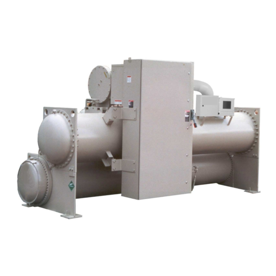
Summary of Contents for Daikin DWSC 050
- Page 1 Installation, Operation and Maintenance Manual D-EIMWC00804-14EN Single/Dual Compressor Centrifugal Chillers DWSC/DWDC 050, 063, 079, 087, 100, 113, 126, Cooling Only DWCC 100, 113, 126 DHSC 050, 063, 079, 087, 100, 126, Heat Recovery Original Instructions...
- Page 2 IMPORTANT The units described in the present manual represent a valuable investment. Maximum care should be taken to ensure correct installation and appropriate working conditions of the units. Installation and maintenance must be performed by qualified and specifically trained personnel only. Correct maintenance of the unit is indispensable for its safety and reliability.
-
Page 3: Warnings For The Operator
Warnings for the operator The operator must read this manual before using the unit. The operator must be trained and instructed on how to use the unit. The operator must strictly follow local safety regulation and laws. The operator must strictly follow all instruction and limitation given for the unit Key to symbols Important note: failure to respect the instruction can damage the unit or compromise functioning Note regarding safety in general or respect of laws and regulations... - Page 4 Unit Control Panel 1 – Non flammable gas symbol 5 – Unit nameplate data 2 – Electrical hazard symbol 6 – Unit characteristics technical 3 – Gas type 7 – Emergency stop 4 – Control panel code Compressor Control Panel 1 –...
-
Page 5: Table Of Contents
Table of Contents Warnings for the operator ..................... 4 Introduction ..................... 8 General Description ......................8 Application ........................... 8 Nomenclature ........................8 Installation......................9 Receiving and Handling ....................... 9 Location and Mounting ...................... 10 Operating/Standby Limits ....................10 Safety ..........................11 System Water Volume ...................... - Page 6 Information and illustrations cover the Daikin products at the time of publication and we reserve the right to make changes in design and construction at anytime without notice. D-EIMWC00804-14EN Centrifugal Chillers...
-
Page 7: Introduction
(latest version available on www.daikineurope.com), for details on operation of the MicroTech II™ unit controller. All Daikin centrifugal chillers are factory tested prior to shipment and must be initially started at the job site by a factory trained Daikin service technician. Failure to follow this startup procedure can affect the equipment warranty. -
Page 8: Installation
Extreme care must be used when rigging the equipment to prevent damage to the control panels or refrigerant piping. See the certified dimension drawings included in the job submittal for the center of gravity of the unit. Consult the local Daikin sales office for assistance if the drawings are not available. -
Page 9: Location And Mounting
Figure 2, DDWDC Major Component Location Oil Sump, Pump, Heaters Motor Terminal Box Rigging Eyes Rigging Eyes Condenser Dual Relief Valves Common Oil Lubrication & Cooler Water Condenser Compressor Connections Control Boxes Note: 1. Chilled water and condenser connection location can vary. Check markings on unit or consult unit certified drawings for connection locations on specific units. -
Page 10: Safety
1 1/8" (28.5 mm) mounting holes are provided in the unit support at the four corners. Note: Units are shipped with refrigerant and oil valves closed to isolate these fluids for shipment. Valves must remain closed until start-up by the Daikin technician. Nameplates There are several identification nameplates on the chiller: •... -
Page 11: System Water Volume
Lower temperatures will improve chiller performance. Up to 300 Tons Daikin centrifugal chillers up to 300 tons are equipped with electronic expansion valves (EXV) and will start and run with entering condenser water temperatures as low as shown in Figure 3 or as calculated from the following equation on which the curves are based. - Page 12 Figure 3, Minimum Entering Condenser Water Temperature (EXV) Minimum Entering Condenser Water Temperature - 10 F Range 65.0 44 LChWT 42 LChWT 46 LChWT 60.0 55.0 50.0 45.0 40.0 35.0 30.0 Percent Load Min. ECWT = 5.25 + 0.88*(LWT) - DT (PLD/100) + 22*(PLD/100) •...
- Page 13 As chillers are selected for lower kW per ton, the cooling tower fan motor power becomes a higher percentage of the total peak load chiller power. Daikin’s Energy Analyzer program can optimize the chiller/tower operation for specific buildings in specific locales.
-
Page 14: Water Piping
It is also possible to build up a frequency beat due to the slight difference in the operating rpm of the pump motor and the Daikin centrifugal motor. Daikin encourages the use of 1750/1460 rpm (four-pole) pump motors. - Page 15 They also serve to shut down the unit in the event that water flow is interrupted to guard against evaporator freeze-up or excessive discharge pressure. Thermal dispersion flow switches are available from Daikin as a factory-mounted option. It is mounted in an evaporator and condenser water nozzle and factory wired.
- Page 16 CAUTION Freeze Notice: Neither the evaporator nor the condenser is self-draining; both must be blown out to help avoid damage from freezing. The piping should also include thermometers at the inlet and outlet connections and air vents at the high points. The water heads can be interchanged (end for end) so that the water connections can be made at either end of the unit.
- Page 17 Figure 7, Heat Recovery Schematic HEAT LOAD AUXILIARY HEATER OPEN CIRCUIT RECOVERY TOWER CONDENSER TOWER HEAT RECOVERY CONDENSER CHILLER LEGEND EVAPORATOR TC TEMPERATURE CONTROL POINT PUMP COOLING LOAD Centrifugal Chillers D-EIMWC00804-14EN...
-
Page 18: Field Insulation Guide
Field Insulation Guide Figure 8, Insulation Requirements, Cooling-only Units D-EIMWC00804-14EN Centrifugal Chillers... - Page 19 Centrifugal Chillers D-EIMWC00804-14EN...
-
Page 20: Physical Data And Weights
Actual charge for a specific selection can vary with tube count and can be obtained from the Daikin Selection Program. The program will not allow a selection where the unit charge exceeds the condenser pumpdown capacity. - Page 21 (1552 kPa) on DWDC units. Water side design is 150 psi (1034 kPa) on all. Pumpdown To facilitate compressor service, all Daikin centrifugal chillers are designed to permit pumpdown and isolation of the entire refrigerant charge in the unit’s condenser.
-
Page 22: Oil Coolers
Oil Coolers Daikin centrifugal chillers, sizes 063 through 126, have a factory-mounted, water-cooled oil cooler, temperature-controlled water regulating valve and solenoid valve per compressor. Model 050 chillers have refrigerant-cooled oil coolers and require no cooling water connection. DWSC/DHSC single compressor cooling water connections are located near the compressor and are shown on the specific unit certified drawings. - Page 23 2. Pressure drops include valves on the unit. Table 7, Freestanding VFD, Cooling Requirements Cooling Cooling Cooling Cooling Water Water Water Water DWSC/DHSC 063 - 087 Flow, gpm Inlet Temperature, °F 80.0 65.0 55.0 45.0 Outlet Temperature, °F Pressure Drop, ft. 13.0 DWSC/DHSC 100 - 126 Flow, gpm...
- Page 24 Figure 10, Oil Cooler Piping With City Water OIL COOLER SOLENOID VALVE COOLING TOWER STOP WATER VALVE SUPPLY STRAINER COOLING TOWER MAKEUP MAX. 40 DISCHARGE ABOVE MESH HIGHEST POSSIBLE DRAIN VALVE WATER LEVEL OR PLUG OPEN DRAIN Figure 11, Oil Cooler Connections, DWSC/DHSC Units Compressor Reservoir Controller &...
-
Page 25: Oil Heater
Oil Heater The oil sump is equipped with an immersion heater that is installed in a tube so that it can be removed without disturbing the oil. Relief Valves As a safety precaution and to meet code requirements, each chiller is equipped with pressure relief valves located on the condenser, evaporator, and oil sump vessel for the purpose of relieving excessive refrigerant pressure... -
Page 26: Electrical
ID, outlet pressure and back pressure. The formula, and tables derived from it, is contained in ASHRAE Standard 15-2001. Daikin centrifugal units have relief valve settings of 180 psi, 200 psi, and 225 psi, and resultant valve discharge capacities of 68.5 # air/min, 75.5 # air/min, and 84.4 # air/min respectively. - Page 27 It is the installing contractor's responsibility to insulate the compressor motor terminals when the unit voltage is 600 volts or greater. This is to be done after the Daikin start-up technician has checked for proper phase sequence and motor rotation.
-
Page 28: Remote Starter Display Wiring
Figure 14, Field Wiring for Optional Display Control Power Wiring The control circuit on the Daikin centrifugal packaged chiller is designed for 115-volts. Control power can be supplied from three different sources: 1. If the unit is supplied with a factory-mounted starter or VFD, the control circuit power supply is factory-wired from a transformer located in the starter or VFD. - Page 29 2. A freestanding starter or VFD furnished by Daikin, or by the customer to Daikin specifications, will have a control transformer in it and requires field wiring to terminals in the compressor terminal box. 3. Power can be supplied from a separate circuit and fused at 20 amps inductive load. The control circuit disconnect switch must be tagged to prevent current interruption.
- Page 30 Minimum wire size for 115 Vac is 12 GA for a maximum length of 50 feet. If greater than 50 feet, refer to Daikin for recommended wire size minimum. Wire size for 24 Vac is 18 GA. All wiring to be installed as NEC Class 1 wiring system. All 24 Vac wiring must be run in separate conduit from 115 Vac wiring.
- Page 31 13. Optional Protocol Selectability BAS interfaces. The locations and interconnection requirements for the various standard protocols are found in their respective installation manuals, obtainable from the local Daikin sales office and also shipped with each unit: Modbus IM 743-0 LonWorks IM 735-0 BACnet IM 736-0 The “Full Metering”...
- Page 32 Figure 15, Field Wiring Diagram MICROTECH CONTROL BOX TERMINALS (115V) (24V) POWER * NOTE 7 NEUTRAL * NOTE 10 * COOLING TOWER FOURTH STAGE STARTER * NOTE 10 * COOLING TOWER THIRD STAGE STARTER * NOTE 10 * COOLING TOWER SECONDH STAGE STARTER...
-
Page 33: Multiple Chiller Setup
Setup Interconnecting MicroTech II pLAN RS485 wiring should be installed by the installing contractor prior to start-up. The Daikin start-up technician will check the connections and make the necessary set point settings. 1. With no pLAN connections between chillers, disconnect chiller control power and set the DIP switches as shown in Table 11. - Page 34 Figure 16, Communication Wiring PIGTAIL Chiller A J10 J11 OPDR UNIT CONTROL BLU/WHT WHT/BLU SHIELD Chiller B PORT OPDR J11 PORT UNIT CONTROL BLU/WHT WHT/BLU SHIELD Chiller C (+) (-) J11 Port UNIT CONTROL NOTE: A fourth chiller, Chiller D would be connected to chiller C same as chiller C to chiller B. Table 11, Address DIP Switch Settings for Controllers Using pLAN.
- Page 35 MicroTech II Operator Interface Touch Screen (OITS) Settings Settings for any type of linked multiple compressor operation must be made to the MicroTech II controller. Settings on a dual compressor unit are made in the factory prior to shipment, but must be verified in the field before startup. Settings for multiple chiller installations are set in the field on the Operator Interface Touch Screen as follows: Maximum Compressors ON –...
-
Page 36: Prestart System Checklist
Minimum system load of 80% of machine capacity available for testing and adjusting controls ....................... (*) Includes heating hot water on heat recovery units. Note: This checklist must be completed and sent to the local Daikin service location two weeks prior to start-up. D-EIMWC00804-14EN... -
Page 37: Operation
OM CentrifMicro II (latest edition) and the control diagram furnished with the unit before starting, operating, or shutting it down. During the initial startup of the chiller the Daikin technician will be available to answer any questions and instruct in the proper operating procedures. - Page 38 NOTE: Detailed information on the operation of the MicroTech II control is contained in the OM CentrifMicro II operating manual. Figure 18, Unit Control Panel ON/OFF Switches UTB1 Unit Terminal Block 110-volt Circuit Breaker pLAN Termination Unit & Control Power Controller Isolation Board Emergency...
-
Page 39: Capacity Control System
Capacity Control System The opening or closing of the inlet vanes controls the quantity of refrigerant entering the impeller thereby controlling the compressor capacity. The vane movement occurs in response to oil flow from the SA or SB 4-way solenoid valves, which in turn, respond to instructions from the unit microprocessor as it senses leaving chilled water temperature. - Page 40 Table 12, Vane Speed Factory Setting Compressor Model Opening Time Closing Time CE050 2 - 2 1/2 min. 3/4 - 1 min. CE063 - CE100 3 - 5 min. 1 - 2 min CE126 5 - 8 min. 1 - 2 min. Figure 21, Oil Sump and Compressor Controller Panel Back Seat Port Oil Pump...
- Page 41 Figure 22, Vane Control Solenoid Operation LEGEND HOLDING Oil Under Pressure Compressor Floating Piston Linked to Inlet Vanes Unloader Opens Vanes Cylinder Closes Vanes Four-Way Solenoid Piston Drain Valve Located on To Oil Compressor or #3 Outlet Pump Sump in Lube Box Section “SB”...
-
Page 42: Surge And Stall
735030435, Rev 47 Compressor Oil Label 070200106, Rev OB NOTES: Approved oil from two suppliers can be mixed, although they have slightly different viscosity. Lubricant from either supplier can be furnished when ordering by Daikin part number. D-EIMWC00804-14EN Centrifugal Chillers... -
Page 43: Hot Gas Bypass
When the ambient wet bulb temperature is lower than design, the entering condenser water temperature can be allowed to fall, improving chiller performance. Daikin chillers will start with entering condenser water temperature as low as 55°F (42.8°C) providing the chilled water temperature is below the condenser water temperature. - Page 44 Even with tower fan control, some form of water flow control such as tower bypass must be used. D-EIMWC00804-14EN Centrifugal Chillers...
-
Page 45: Maintenance
It is useful to have an oil analysis at initial startup to provide a benchmark from which to compare future tests. The local Daikin service office can recommend suitable facilities for performing these tests. - Page 46 Changing Oil Filters Daikin chillers are at positive pressure at all times and do not leak contaminated moist air into the refrigerant circuit, thereby eliminating the need for annual oil changes. An annual laboratory oil check is recommended to check overall compressor condition.
- Page 47 Refrigerant Cycle Maintenance of the refrigerant cycle includes maintaining a log of the operating conditions, and checking that the unit has the proper oil and refrigerant charge. At every inspection, the oil, suction, and discharge pressures should be noted and recorded, as well as condenser and chiller water temperatures.
-
Page 48: Annual Shutdown
If the operator has any reason to suspect that the power system connections have been altered, (phases reversed) the compressor must be jogged to check rotation. For assistance, call the local Daikin service location. Cleaning and Preserving A common cause of service calls and equipment malfunction is dirt. -
Page 49: Annual Startup
The use of untreated water can result in corrosion, erosion, sliming, scaling or algae formation. It is recommended that the service of a reliable water treatment company be used. Daikin assumes no responsibility for the results of untreated or improperly treated water. -
Page 50: Repair Of System
Repair of System Pressure Relief Valve Replacement Current condenser designs use two relief valves separated by a three-way shutoff valve (one set). This three-way valve allows either relief valve to be shut off, but at no time can both be shut off. - Page 51 Evacuation After it has been determined that there are no refrigerant leaks, the system must be evacuated using a vacuum pump with a capacity that will reduce the vacuum to at least 1000 microns of mercury. A mercury manometer, or an electronic or other type of micron gauge, must be connected at the farthest point from the vacuum pump.
-
Page 52: Oil Analysis
Table 1 indicates these parameters. In general Daikin does not recommend changing lubricating oils and filters on a periodic basis. The need to change lubricating oil and filters should be based on a careful consideration of oil analysis, vibration analysis and knowledge of the operating history of the equipment. - Page 53 The source of tin may be from bearings. Zinc There is no zinc used in the bearings on Daikin chillers. The source, if any may be from additives in some mineral oils. Lead The source of lead in Daikin centrifugal chillers is the thread sealant compounds used during chiller assembly.
- Page 54 While the unit is in operation, the sample should be taken from a stream of refrigerant oil, not in a low spot / quiet area. Table 15, Upper Limit For Wear Metals And Moisture In Polyolester Oils In Daikin Centrifugal Chillers Elements Upper Limit (ppm)
-
Page 55: Maintenance Schedule
Maintenance Schedule Maintenance Check List Item I. Unit · Operational Log · Analyze Operational Log · Refrigerant Leak Test Chiller · Test Relief Valves or Replace II. Compressor · Vibration Test Compressor A. Motor · Meg. Windings (Note 1) · Ampere Balance (within 10% at RLA) ·... - Page 56 Daikin's high efficiency heat exchangers have very low design approach temperatures, in the order of one to one and one half degrees F.
-
Page 57: Service Programs
3 to 4 weeks of normal operation on a new installation, and on a regular basis thereafter. Daikin offers a variety of maintenance services through the local Daikin service office, its worldwide service organization, and can tailor these services to suit the needs of the building owner. -
Page 58: Obligatory Routine Checks And Starting Up Apparatuses Under Pressure
Obligatory routine checks and starting up apparatuses under pressure The units are included in category IV of the classification according to European Directive PED 97/23/EC For chillers belonging to this category, some local regulations require a periodic inspection by an authorized agency. Please check with your local requirements. -
Page 59: Important Information Regarding The Refrigerant Used
Important information regarding the refrigerant used This product contains fluorinated greenhouse gases covered by the Kyoto Protocol. Do not vent gases into the atmosphere. Refrigerant type: R134a GWP(1) value: 1300 (1)GWP = global warming potential The refrigerant quantity is indicated on the unit name plate. Periodical inspections for refrigerant leaks may be required depending on European or local legislation. - Page 62 The present publication is drawn up by of information only and does not constitute an offer binding upon Daikin Applied Europe S.p.A.. Daikin Applied Europe S.p.A. has compiled the content of this publication to the best of its knowledge. No express or implied warranty is given for the completeness, accuracy, reliability or fitness for particular purpose of its content, and the products and services presented therein.
Need help?
Do you have a question about the DWSC 050 and is the answer not in the manual?
Questions and answers