Daikin Clima-Flex CLIC Series Control Manual
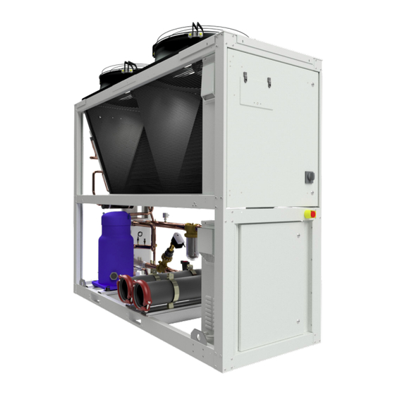
Air-cooled scroll compressor chiller water generator unit
Hide thumbs
Also See for Clima-Flex CLIC Series:
- Control manual (30 pages) ,
- Installation, operation and maintenance manual (118 pages)

Subscribe to Our Youtube Channel
Related Manuals for Daikin Clima-Flex CLIC Series


Summary of Contents for Daikin Clima-Flex CLIC Series
- Page 1 Control Manual Group: Chiller Part Number: CM CLIC Date: 28 May 2024 CLIC Series Air-Cooled Scroll Compressor Chiller Water Generator Unit Model 25 to 250 RT Refrigerant R-410A/R-454B 60 Hz...
-
Page 2: Table Of Contents
Table of Contents Safety Warnings..........3 History Trend............9 Ansi:Z535.5 Definitions........3 Inputs/Outputs...........10 General Description........4 Inputs..............10 Nomenclature...........4 Outputs..............10 Features / Benefits........5 Settings.............10 Efficiency............5 General..............11 Flexibility............5 Temperature Control..........11 Safety.............5 Inverter Compressor..........11 Design..............5 Pump Down Configuration........11 Communication..........5 Electronic Expansion..........11 Installation............5 Superheat..............11 Maintenance...........5 Oil Management............12 User Interface..........6 Drive Configuration..........12 Screen Overview..........6 External Coil............12... -
Page 3: Safety Warnings
Safety Warnings ! DANGER ! ! WARNING ! LOCK OUT/LABEL all power sources before starting, pres- Polyolester oil, commonly referred to as POE oil, is a syn- surizing, depressurizing or shutting down the chiller. thetic oil used in many refrigeration systems and may be present in this Clima Flex product. -
Page 4: General Description
General Description generation evaporators, air cooler condensers, optional hydraulic Our units are built with design and control in mind, so we use components and various safety protections. specialized technical control software. Some of our special features are our own piping and wiring, Scroll type compressors, new Our units are ecofriendly and operate with R-454B refrigerant. -
Page 5: Features / Benefits
Features / Benefits EFFICIENCY DESIGN Our units are designed to meet the needs of any project. Research conducted by the Engineering Department has resulted Our intelligent process controllers and smart temperature sensors in units with high design efficiency and optimum performance. The selection of the main components, our quality and control system provide maximum performance and energy savings. -
Page 6: User Interface
User Interface SCREEN OVERVIEW The main screen consists of two sections. Chiller status area. Main display. Setting area. Figure 1. Home Screen CHILLER STATUS AREA The chiller status area, basically content the main information about chiller status and control appears on the face of the buttons and touch targets. -
Page 7: Main Display
User Interface Value of temperature The value shows the measure of temperature, of the calculation of SH SuperHeat Value of % of Open Dregree The value shows the measured percentage of open degree, of the EXV Electronic Expansion Valve Value of % demand of the The value shows the measured percentahe of demand, of the condenser condenser The indicator shows the status of flow switch, red = without flow and... -
Page 8: Settings Area
User Interface SETTINGS AREA Figure 3. Stop The Chiller Confirmation Screen The setting area, when touched, each of the buttons in this area Button interacts with other parameters screens. Table 2 provides a Power description of each button. Table 2. Settings Area LABEL ICON DESCRIPTION... -
Page 9: Alarms History Screen
User Interface 10. Button go to the trend history. Alarms History Screen 11. Button go to the second screen about Realtime trend for the Other button is Alarm History if you short press, you show the rest of the sensor. alarms history table. -
Page 10: Inputs/Outputs
User Interface Figure 9. Realtime Trend (Screen 1) Figure 11. Inputs Screen Outputs Outputs screens show the value each output wiring in the analog The second screen about history trend, continues the rest of outputs also and state of each digital output. The call out numbers sensors, just when you press the button one you can back to the refer to the following: screen one. -
Page 11: General
User Interface Panel fan Inverter Compressor Crankcase control Maintenance Button up. Button down. Figure 13. General Setting Screen Pump Down Configuration General Electronic Expansion Temperature Control Superheat www.clima-flex.com cm-clic454-cf-eng... -
Page 12: Oil Management
User Interface Oil Management Alarm Configuration Drive Configuration Panel Fan External Coil Cranckcase Control Data Log Maintenance cm-clic454-cf-eng www.clima-flex.com... -
Page 13: Controller Interface
Controller Interface MXC controller has a LCD display where the chiller can be configured and operated. Main Screen Keyboard Refrigeration Circuit Status Screen www.clima-flex.com cm-clic454-cf-eng... - Page 14 Controller Interface The access this screen, from main screen press Scroll Down button. Analog Inputs Screen Each alarm is described through an alarm description (for LCD display only), an alarm code and the time since its activation in the format hours:minutes:seconds (seconds for LCD display only). Note: You can also access alarm visualization by pressing the ESC key from the main screen.
-
Page 15: Chiller Parameters Configuration
Chiller Parameters Configuration This table shows all the parameters that can be configured according to application. LABEL DESCRIPTION VALUE/TYPE UNIT General > Setup ON/OFF 0 - OFF Enum 1 3001 System heat/cool 0 - COOL Enum 2 3002 Unit Type 0 - MOTHER Enum 25 3003... - Page 16 Chiller Parameters Configuration Minimum Speed 100.0 30.0 3041 Maximum Speed 100.0 100.0 3042 Parameters > Evaporator Number of Evaporator Pumps 3043 Flow Switch Alarm Reset Type 3044 Parameters > Pump Down Config Pump Down Startup Pressure Set 30.0 10.0 3045 Pump Down Stop Pressure Set 30.0 3046...
- Page 17 Chiller Parameters Configuration SH close Tn divide 3082 SH close Kp factor 10.0 3083 MSS Stability 10.0 3084 MSS T0 stability factor 3085 MOP function 0 - OFF Enum 1 3086 MOP setpoint -70.0 60.0 °C 3087 LOP function 0 - OFF Enum 1 3088 LOP setpoint...
- Page 18 Chiller Parameters Configuration Ramp Down 1000 3125 0 - No Oper- DI 18 Enum 19 3126 ation 0 - No Oper- DI 19 Enum 20 3127 ation 6 - StopIn- DI 27 Enum 21 3128 verse Start Delay 360.0 180.0 3129 Start Speed 1800...
- Page 19 Chiller Parameters Configuration Ice Alarm Threshold -20.0 20.0 °C 3154 Ice Alarm Differential 20.0 °C 3155 Ice Alarm Action With Unit Off 1 - PON Enum 11 3156 Alarm Config > High Pressure High Pressure Alarm Reset Typer 3157 Delay from compressor starting 3158 Enable HP Alarm from Sensor 1 - YES...
-
Page 20: Digital Inputs
Chiller Parameters Configuration Discharge Pressure 45.0 0-5 V Read 18504 Crankcase Temp -50.0 110.0 NTC-10K Read 18510 Main Water Iny Temp -50.0 110.0 NTC-10K Read 18512 Main Water Ret Temp -50.0 110.0 NTC-10K Read 18513 Discharge Temperature -50.0 110.0 NTC-10K Read 18507 Liquid Temperature... - Page 21 Chiller Parameters Configuration Water Valve N.O. Read 18017 Chiller Status On.Off N.O. Read 18013 Alarm Status N.O. Read 18002 Start Compressor N.O. Read 18004 www.clima-flex.com cm-clic454-cf-eng...
-
Page 22: Mother /Son Logic
Mother /Son Logic • ON/OFF Control – Main Loop Control: Chiller can be started/ The program was developed in MCXDesing and there is only one single program for both units. There is parameter where the service stopped by a digital input number 1 (on/off switch) and HMI technician must select between mother or son configuration. - Page 23 Mother /Son Logic Table 3. List of alarms with levels and type of alarms LABEL DESCRIPTION VALUE/TYPE UNIT Modbus ALARMS LABEL DESCRIPTION RESET IN OFF Temperature Evaporator In Fault AUTO ACTIVE Read 1901 .08 Temperature Evaporator Out Fault AUTO ACTIVE Read 1901 .09 Suction Temperature Fault...
- Page 24 Mother /Son Logic VZH Map - HP Ratio/HP AUTO ACTIVE Read 1902 .04 VZH Map - High Suction Pressure AUTO ACTIVE Read 1902 .05 VZH Map - LP Ratio/Low Cond AUTO ACTIVE Read 1902 .06 VZH Map - Abnormal DischP/SuctP AUTO ACTIVE Read...
- Page 25 Mother /Son Logic Liquid Press Fault AUTO ACTIVE Read 1904 .03 Main Water Iny Temp Fault AUTO ACTIVE Read 1904 .04 Main Water Ret Temp Fault AUTO ACTIVE Read 1904 .05 Ovld Comp Relay Warning AUTO ACTIVE Read 1904 .06 Overload Compressor Warrnig AUTO ACTIVE...
- Page 26 Mother /Son Logic Regulation control: On this section the program with calculate the The compressor has an oil level switch, and the VZH oil manager Cooling Power demand according to the value of actual Leaving is configured based on oil lever sensor, it means that only when the Water Temperature versus the Set Point defined by the user.
- Page 27 Mother /Son Logic Deadband Control[Coding Priority 1]: • The PI gain and Integral time have been tuned a bit. An offset has been added to the PI. Deadband parameter is set by the User: Param_Db. • Fan selection now occurs based on Jordan's logic. Actual Deadband values: ±Db = Ptarget ±...
-
Page 28: Modbus Integration And Wiring
Modbus Integration And Wiring For the integration with the MCX controller you need to follow the next wiring; It´s very important validate the polarity of the Modbus protocol in both devices also assure in RS-485 of HMI pins 1-2 and 4-3 must be connected externally. Figure 16. - Page 29 THIS PAGE IS INTENTIONALLY LEFT BLANK www.clima-flex.com cm-clic454-cf-eng...
- Page 30 cm-clic454-cf-eng www.clima-flex.com...
Need help?
Do you have a question about the Clima-Flex CLIC Series and is the answer not in the manual?
Questions and answers