Daikin Clima-Flex CLIC Series Control Manual
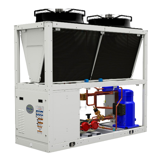
Air-cooled fixed compressor chilled ice water generator unit
Hide thumbs
Also See for Clima-Flex CLIC Series:
- Installation, operation and maintenance manual (118 pages) ,
- Control manual (30 pages)

Related Manuals for Daikin Clima-Flex CLIC Series


Summary of Contents for Daikin Clima-Flex CLIC Series
- Page 1 Control Manual Group: Chiller Part Number: CM CLIC Date: 8 November 2022 CLIC Series Air-Cooled Fixed Compressor Chilled Ice Water Generator Unit Model 25 to 250 TR Refrigerant HFC-410A 50/60 Hz...
-
Page 2: Table Of Contents
Table of Contents Safety Warnings............3 General Description..........4 Features / Benefits.............5 Control................7 Connectivity/Communication........24 Appendices............26 Manufactured in an ISO 9001 certified facility 2022 Clima Flex . Illustration and data cover the Clima Flex product at the time of publication and we reserve the right to make changes in design and construction at any time without notice. -
Page 3: Safety Warnings
Safety Warnings This manual provides information on the control data of the Clima Flex CLIC series. NOTES: Installation and maintenance must be performed only by qualified personnel who are familiar with local codes and regulations and who have experience with this type of equipment. DANGER LOCK OUT/LABEL all power sources before starting, pressurizing, depressurizing or shutting down the chiller. -
Page 4: General Description
General Description Our units are built with design and control in mind, so we use Our units are environmentally friendly and operate with R-410A specialized technical control software. Some of our special refrigerant. features are our own piping and wiring, fixed type compressors, new generation evaporators, air cooler condensers, optional hydraulic components and various safety protections. -
Page 5: Features / Benefits
Features / Benefits EFFICIENCY DESIGN Our units are designed to meet the needs of any project. Research conducted by the Engineering Department has resulted Our intelligent process controllers and smart temperature sensors in units with high design efficiency and optimum performance. The selection of the main components, our quality and control system provide maximum performance and energy savings. - Page 6 Features / Benefits TESTING Each unit is pressure and vacuum tested and then charged with the refrigerant required for proper operation based on the customer’s installation conditions. The units are evaluated at full load operation with water flow, heat load and line voltage placed at actual operating conditions. NOTE: The warranty policy requires that commissioning be performed by qualified personnel authorized by the company.
-
Page 7: Control
Control PCO SYSTEM Table 1. Description of PCO Control Equipment The system is designed to handle one unit with capacity control DESCRIPCIÓN by means of a drive or a typical unloading valve on a digital fixed Power connector [G(+), G0(-)]. compressor, this is a unit called “Mother”... - Page 8 Control EXPANSION TABLE TEMPERATURE SENSOR Figure 3. Expansion Table or Module The PT10K NTC Temperature Sensor is resistant to temperature changes, the relationship with the curve is the higher the temperature, the lower the resistance and vice versa. DIGITAL INPUT (REMOTE ON/OFF, OPERATION...
- Page 9 Control INPUTS AND OUTPUTS Table 10. pCOe Digital Inputs (Expansion Module Son) The configuration of the inputs and outputs depends on the initial PORT CO AIR HP AIR HP WATER TYPE WATER configuration of the system. HIGH PRESSURE HIGH PRESSURE The tables in this section show the inputs and outputs assigned to LOW PRESSURE LOW PRESSURE...
- Page 10 Control On/Off (Reset) If the flow detection fails after the period allotted for digital input detection, it is necessary to turn off the pump and restart it to make an attempt after the waiting time between lapses has elapsed. If The operating sequence starts with a check of after a certain number of attempts the flow is still not detected, the all pre-programmed safety check points, if the...
- Page 11 Control UNIT ROTATION Figure 7. Example of the proportional control cycle, for cases of total demand or demand for the “Mother” unit. When the system is operating in “Tandem” mode, the total demand is calculated as mentioned in the previous section, depending on how many units are operating, the system will request the Demanda (%) activation or suspension of the same in order to meet the demand.
- Page 12 Control cooled unit, a command will be sent to start the condenser fan. To COMMUNICATION PROTOCOL restart, keep the unit on high output, the compressor will not start until the programmed time has elapsed. The pCO has 4 independent communication ports configured as •...
- Page 13 Control Alarms Always Visible, sends user to Alarms page Home Sends the user to the Main Menu Return to Sends the user to the last accessed page Main Menu Sends the user to the Main Menu Alarm log Sends the user to the Alarm Log page Inputs and Outputs Sends user to the Inputs and...
- Page 14 Control By pressing the “Active Alarms” button, this screen will be displayed: These properties are edited in the on-screen navigation menu where the graphs are displayed by pressing the “Graph Settings” button. The pGD Touch terminal stores a reading of each of the temperatures mentioned above (Injection and main return, and injection temperature of each enabled unit) every 180 seconds (3 minutes) and can store over 100,000 samples of data before...
- Page 15 Control To access the menu of the Level 1, 2 and 3 sections, the user Device Configuration must go to the “Access” section and enter the password for the Level 3 corresponding level. (Password 3) The Level 3 password allows access to all levels, Level 2 accesses Level 3 Level 1 and 2, Level 1 only allows access to this level.
- Page 16 Control If the unit icon is clicked, the user will be sent to the “Summary” page, where more detailed information about the unit can be found. In this section you can see the inputs of the system (temperature sensors, digital inputs of suction and discharge pressure of the motor protection) as well as the outputs of the unit (compressor, pump and fan).
- Page 17 Control MODE SELECTION The selection mode screen is divided into 2 sections: • The mode of the terminal’s work selection or Digital Input. • Current Work Mode Indicator The operating mode selection can be configured in 2 ways: By digital input or by selecting it on the terminal (“Configuration” section).
- Page 18 Control SETTINGS In the settings section, protected level password, parameters for the control and management of the cooling demand (and heating systems configured as heat pump) are displayed. parameters Individual control in “Son” units only requires the following parameters: Central Control (“Tandem”...
- Page 19 Control Also in the “Son” section it is possible to configure the switching on It is also possible to calibrate the minimum flow rate allowed to and off of the same, this configuration is a prevention to avoid the start the system, the Water Chiller Unit system needs 2.4 gallons/ freezing or cold water alarm in the “Tandem”...
- Page 20 Control DELETION OF RECORDS DEFROST CONFIGURATION In the last part of Level 2 of the Navigation Menu, the user can delete the historical graphs and alarm records from the internal Only for Air-Water systems with Heat Pump function. memory of the pGD Touch terminal. 1.
- Page 21 Control FREEZING AND COLD WATER ALARM The freezing and cold water logic is the same, except that one considers the freezing sensor and the other the injection sensor as the main source of information. For each of the alarms, an activation value, a reset and recovery time (where the unit with an active alarm will not be reset) must be set.
- Page 22 Control REFRIGERANT ALARM The refrigerant alarm is a user-enabled warning that evaluates the change in the injection temperature sensor when the compressor starts running. If it detects any change in the set time, the alarm is activated. This alarm will not stop any control process. In this section the user can enable and disable the alarm, and if applicable, set the minimum detection range and the maximum time in which this change must occur to not activate the alarm.
- Page 23 Control/Connectivity PCOE EXPAN- SERIAL SETTINGS SWITCHES IN PCOE SION MODULE ADDRESS CHILD UNIT 1 The devices use NOIP Dynamic Domain Name Server (DDNS) technology to be accessible from outside the local area network (LAN). CHILD UNIT 2 You need to configure the DDNS service and other settings on your LAN router.
-
Page 24: Connectivity/Communication
Connectivity/Communication ROUTER ACCESS Login from a web browser (Chrome, Safari, IE, etc) to the control Domain Name: UnidadDeAC. panel of your router, for this purpose simply enter the IP address of MiDominio.com the router in your browser. You can find out the IP address of your router by typing IPCONFIG from a Windows Command Prompt Internal IP Address: window, the result it gives you under “Default Gateway”... - Page 25 Connectivity/Communication 3. Once VNC Viewer for Chrome is installed and you are ready to continue running the extension, you will be presented with the following screen with two parameters. Address: This can be the IP address or Domain Name of your REMOTE OPERATION OF EQUIPMENT computer, remember that if you are INSIDE your local area network (LAN) you must use the IP address, and if you are OUTSIDE your...
-
Page 26: Appendices
Appendices CLIC MAPPING TABLE Al_congelamiento_E2 DigitalInput MODBUS Al_congelamiento_E3 DigitalInput CODE MODBUS FUNCTION TYPE READ ADDRESS Al_Agua_Helada_E1 DigitalInput Al_congelamiento_E4 DigitalInput Al_Agua_Helada_E10 DigitalInput Al_congelamiento_E5 DigitalInput Al_Agua_Helada_E2 DigitalInput Al_congelamiento_E6 DigitalInput Al_Agua_Helada_E3 DigitalInput Al_congelamiento_E7 DigitalInput Al_congelamiento_E8 DigitalInput Al_Agua_Helada_E4 DigitalInput Al_congelamiento_E9 DigitalInput Al_Agua_Helada_E5 DigitalInput Al_congelamiento_M DigitalInput Al_Agua_Helada_E6 DigitalInput... - Page 27 Appendices Al_flujoE7 DigitalInput ED_sensor_flujo_E9 DigitalInput Al_flujoE8 DigitalInput ED_sensor_flujo_M DigitalInput Al_flujoE9 DigitalInput H_AP_CompE1 5072 AnalogInput Al_flujoM DigitalInput H_AP_CompE10 5424 AnalogInput 5049 AnalogInput H_AP_CompE2 5084 AnalogInput CE10 5376 Holding H_AP_CompE3 5096 AnalogInput 5050 AnalogInput H_AP_CompE4 5108 AnalogInput 5051 AnalogInput H_AP_CompE5 5310 AnalogInput 5052 AnalogInput H_AP_CompE6...
- Page 28 L_AP_CompE10 5425 AnalogInput Reset_Als Coil L_AP_CompE2 5085 AnalogInput Setpoint_cal Holding L_AP_CompE3 5097 AnalogInput Setpoint_enf Holding L_AP_CompE4 5109 AnalogInput Temp_Cabezal_in AnalogInput L_AP_CompE5 5311 AnalogInput Temp_Cabezal_out AnalogInput L_AP_CompE6 5270 AnalogInput Temp_Conden_E1 AnalogInput L_AP_CompE7 5289 AnalogInput Temp_Conden_E10 AnalogInput L_AP_CompE8 5389 AnalogInput Temp_Conden_E2 AnalogInput L_AP_CompE9 5408 AnalogInput...
- Page 29 Temp_iny_Maestro AnalogInput Temp_ret_E1 AnalogInput Temp_ret_E10 AnalogInput Temp_ret_E2 AnalogInput Temp_ret_E3 AnalogInput Temp_ret_E4 AnalogInput Temp_ret_E5 AnalogInput Temp_ret_E6 AnalogInput Temp_ret_E7 AnalogInput Temp_ret_E8 AnalogInput Temp_ret_E9 AnalogInput Temp_ret_Maestro AnalogInput Ventilador_E1 DigitalInput Ventilador_E10 DigitalInput Ventilador_E2 DigitalInput Ventilador_E3 DigitalInput Ventilador_E4 DigitalInput Ventilador_E5 DigitalInput Ventilador_E6 DigitalInput Ventilador_E7 DigitalInput Ventilador_E8 DigitalInput Ventilador_E9...
- Page 30 cm-clic-cf-eng www.clima-flex.com...
Need help?
Do you have a question about the Clima-Flex CLIC Series and is the answer not in the manual?
Questions and answers