Table of Contents
Advertisement
For Overhaul and Inspection
Semi-Hermetic Single Screw
Compressor Version
[Applied Models]
ZH(C)3LSF
ZH3LMF
ZH(C)5MLF
ZH5SLF
ZH(C), (A)5LLF
ZH5LMF
ZH(C), (A)7SLF
ZHA7MLF ZH(C), (A)5WLG
ZH(C)7LLF
ZHA7MSG ZH(C)7LSG
ZH(C), (A)9SLF
ZH(C), (A)9LLF
Si50-203
ZH(C)3LTG
ZH(C)3WLG
ZH(C), (A)5LMG
ZH(C), (A)7WSG
ZH(C), (A)9LSG
ZH(C), (A)9WSG
Advertisement
Table of Contents

Related Manuals for Daikin ZH(C)3LSF


Summary of Contents for Daikin ZH(C)3LSF
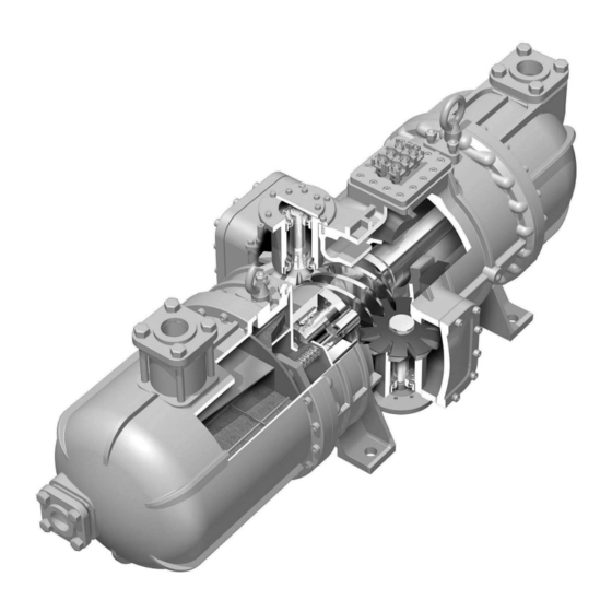
- Page 1 Si50-203 For Overhaul and Inspection Semi-Hermetic Single Screw Compressor Version [Applied Models] ZH(C)3LSF ZH3LMF ZH(C)3LTG ZH(C)5MLF ZH5SLF ZH(C)3WLG ZH(C), (A)5LLF ZH5LMF ZH(C), (A)5LMG ZH(C), (A)7SLF ZHA7MLF ZH(C), (A)5WLG ZH(C)7LLF ZHA7MSG ZH(C)7LSG ZH(C), (A)9SLF ZH(C), (A)7WSG ZH(C), (A)9LLF ZH(C), (A)9LSG ZH(C), (A)9WSG...
-
Page 2: Table Of Contents
Si50-203 Semi-Hermetic Single Semi-Hermetic Single Semi-Hermetic Single Semi-Hermetic Single Screw Compressor Screw Compressor Screw Compressor Screw Compressor Version III Version III Version III Version III 1. Scope of Application ................2 2. Overhaul....................3 3. Periodic Inspection..................4 3.1 Periodic Inspection Items and Intervals............4 3.2 Periodic Inspection Instructions..............5 4. -
Page 3: Scope Of Application
Scope of Application Si50-203 Scope of Application This booklet applies to semi-hermetic single screw compressor for use in Model F type (ZH_F), G type (ZH_G). Replacement intervals specified in the booklet are empirically worked out based on the design service life expected of the compressors operated under the design conditions, and are intended to provide a general guide by which to formulate a maintenance plan. -
Page 4: Overhaul
Si50-203 Overhaul Overhaul Generally, maintenance and inspection of equipment are important in preventing their failure and damage to them. Equipment, even without defective structure or components, gradually age and wear over long years of operation. For example, screw compressors, despite their apparent good operating condition, may face such problems as decreasing insulation resistance of the motor, oil deterioration, and worn and fatigued bearings during long periods of operation. -
Page 5: Periodic Inspection
Periodic Inspection Si50-203 Periodic Inspection “Periodical Inspection” means to inspect, adjust and clean various parts of devices and equipment at the scheduled interval. Periodic Inspection Items and Intervals Table 3-1 shows periodic inspection items and intervals. Conduct inspections at the earliest indicated inspection intervals. -
Page 6: Periodic Inspection Instructions
Si50-203 Periodic Inspection Periodic Inspection Instructions 1. Insulation Resistance of The Motor Insulation Resistance Testing A megger is used to apply voltage directly to an insulated object, measure leakage current through the insulated object, and find the insulation resistance values. Its scale is voltage / leakage graduated with such insulation resistance values. - Page 7 Periodic Inspection Si50-203 2. Changing Refrigerating Oil Oil degrades after many hours of operation and due to aging. Replace oil regularly after 7,500 hours of operation or four years, whichever comes first. (Changing Procedure) (1) Perform a pump down operation to reduce pressure inside the compressor. (2) Release the internal pressure of the compressor.
- Page 8 Si50-203 Periodic Inspection Charging oil Connect a vacuum pump to the suction service port (1/4" DCut) on the casing. While evacuating the compressor, add oil from the discharge service port (3/8" DCut). Use SUNISO 4GSD refrigeration oil (possible for use equal product) for refrigerant R22 and DAPHNE FVC68D refrigerant oil for refrigerant R407C and R134a.
- Page 9 Periodic Inspection Si50-203 (4) Inspection of the gate rotor Visually check the gate rotor surface for scar, chipping, cracking, etc. Check all gate rotor teeth. Table 3-1 Gate rotor inspection standards Item Standard Remedy Cracking No cracking Chipping No chipping 3 mm or more long in long side Replace Scar No scar 1 mm or more deep...
- Page 10 Si50-203 Periodic Inspection Cleaning The Suction Filter (1) Perform a pump down operation to reduce pressure inside the compressor. (2) Release the internal pressure of the compressor. Loosen the flare nut of the service port (with check valve) of the compressor (see Fig. 3-2). Remove the partition lid, then tighten the flare nut to discharge refrigerant from the compressor.
-
Page 11: Overhaul Instructions
Overhaul Instructions Si50-203 Overhaul Instructions The driving and friction parts in the compressor wear for prolonged over time. To prevent accidents caused by worn parts, it is necessary to inspect those parts regularly and overhaul the compressor as needed. Semi-Hermetic Single Screw Compressor Version III... -
Page 12: Disassembly And Inspection
Si50-203 Overhaul Instructions Disassembly and Inspection 1. Draining Oil Drain oil by referring to Section 3.2.2 "Changing refrigerating oil." 2. Remove The Side Caps (One on Each Side) and The Discharge End Cover. (in case of ZH9F, oil collector) Receive remaining oil with a drain pan. Be sure to mount guide bolts when removing the discharge end cover. - Page 13 Overhaul Instructions Si50-203 3. Inspection of The Gate Rotor and Surrounding Parts (1) Checking the slit clearance Measure the slit clearance by referring to Section 3.2.3) "Inspecting The Gate Rotor." (2) Measuring the backlash Measure the backlash of the gate rotor and screw rotor. If the measured value exceed the standard value, replace the gate rotor.
- Page 14 Si50-203 Overhaul Instructions (3) Removing the gate rotor bearing retainer plate While holding the gate rotor with hand, loosen the bolts. Be careful not to lose gate rotor adjusting shims (1) mounted between the gate rotor shaft and retainer plate. Be sure to use the original combination of gate rotor, lower bearing holder, gate rotor adjusting shims and gate rotor adjusting shims (2).
- Page 15 Overhaul Instructions Si50-203 (5) Turn the gate rotor shaft to remove it from the screw rotor. Be careful not to damage the gate rotor. 5. Removing and Installation of Gate Rotor (1) Remove C type retaining ring. (2) Remove the gate rotor from the shaft. (3) Apply red check to the gate rotor, and check that the rotor is free of cracks.
- Page 16 Si50-203 Overhaul Instructions Removing The Motor Rotor (1) Remove the rotor locking plate using a standard screwdriver. (2) Loosen the lock nut. (Use the special tool or jig (1).) (3) As shown in Fig. 4-11 grip rotor fins with pliers, and remove the rotor. Securely support the rotor so as not to drop the rotor.
- Page 17 Overhaul Instructions Si50-203 Disassembly of The Controller Fig. 4-12 Cross sectional diagram of controller (1) Remove the slide valve arm. Loosen the two locking nuts of the slide valve shaft and the bolt at the center of the arm. A thread lock compound was used for the hexagon head bolt at the center. Use an impact wrench to loosen this bolt.
- Page 18 Si50-203 Overhaul Instructions (2) Remove the oil filter using the special tool, and clean. (ZH3F only) After cleaning, dry thoroughly. If the filter is damaged or torn, replace. Fig. 4-14 Oil filter removing tool (3) Remove the mounting bolts, and remove the cylinder cover. (4) Pull out the piston.
- Page 19 Overhaul Instructions Si50-203 Removing and Disassembling The Screw Assembly Pulley (1) Place alignment marks on the casing and main bearing holder. Fig. 4-16 Placing alignment marks on casing and main bearing holder (2) Removing the screw shaft Push the screw shaft from the suction side until the bearing holder completely extends from the discharge side.
- Page 20 Si50-203 Overhaul Instructions Fig. 4-18 Removing screw shaft (2) (3) Disassembling the screw assembly Remove the bolts, and remove the screw bearing retainer plate. Remove the main bearing holder from the screw shaft. Do not lose screw rotor adjusting shims (2). Fig.
-
Page 21: Replacing The Bearing
Overhaul Instructions Si50-203 Replacing The Bearing Unlike slide bearings, roller bearings have limited service life. They must be replaced regularly. To prevent accidents caused by worn roller bearings, replace all roller bearings during an overhaul. 4.2.1 Removing Bearings Main Shaft Bearing (1) Suction end cover (outer ring of cylindrical roller bearing) Remove the C-type retaining ring. - Page 22 Si50-203 Overhaul Instructions Removing the bearing From the opposite side of the end with the C-type retainer ring, remove the outer ring of the bearing by placing a bronze rod and hammering it. Since the outer ring is not pressed in deeply, it can be removed easily. Fig.
- Page 23 Overhaul Instructions Si50-203 4.2.2 Installation of Bearings Before installing the bearings, clean the bearing holder and suction end cover. Main Shaft Bearing (1) Suction end cover (outer ring of cylindrical roller bearing) Hammer the periphery of the outer ring of the cylindrical roller bearing to insert the bearing into the suction end cover bearing housing.
- Page 24 Si50-203 Overhaul Instructions Installing and Adjusting The Gate Rotor Bearings (1) Installing the bearings Install the angular-contact ball bearing and deep groove ball bearing. The bearings must be press-fit, but they do not have to be pressed deeply. Hammer them evenly, and make sure that the bearings rest on the seats.
-
Page 25: Final Assembly
Overhaul Instructions Si50-203 Final Assembly Caution Clean the casing and all other parts, and dry them thoroughly. Use new packings and O-rings. 1. Assembling The Screw Shaft and Main Bearing Holder Install screw adjusting shims (2) and the main bearing holder on the screw shaft, and install the screw bearing retainer plate. - Page 26 Si50-203 Overhaul Instructions 2. Inserting The Screw Shaft Insert the screw shaft into the casing until the shaft contacts the tapered section of the casing. For this process, wear leather gloves to prevent hand injuries. (Do not use fabric work gloves.) The screw shaft is heavy, and the main bearing holder rotates, making it difficult to hold it.
- Page 27 Overhaul Instructions Si50-203 4. Installing The Suction End Cover (1) Extend the screw shaft from the motor side. (2) Install the suction end cover. In this step, use the two positioning pins to position the suction end cover. (Use guide bolts.) (3) Insert the screw shaft into the bearing of the suction end cover.
- Page 28 Si50-203 Overhaul Instructions 6. Installing The Gate Rotor and Adjusting The Slit Clearance (1) Install the O-rings on the lower bearing holder. (ZH_F : two O-rings) (ZH_G : three O-rings (two kinds)···Confirm the installing position on spare parts list.) (2) Set the screw rotor in the position indicated in Fig. 4-5, and engage the screw rotor with the gate rotor.
- Page 29 Overhaul Instructions Si50-203 7. Installing The Main Bearing Holder Fixing Plate, Assembling The Controller, and Installing The Oil Filter (1) Insert the slide valve into the casing. 1 In the right hole, insert the slide valve with "2" stamped on the end surface. 1 Make sure the slide valve operates smoothly.
-
Page 30: Airtightness Test
Si50-203 Airtightness Test 5. Airtightness Test Using dry air mixed with refrigerant, pressurize to . Then, use a gas detector (or soap water) to check for leaks. Apply soap water on the side caps and other cover mounting sections to make sure no air bubbles are formed. -
Page 31: Charging Oil
Charging Oil Si50-203 6. Charging Oil Part of oil may remain in the refrigerating system. Therefore, charge the same amount of oil removed from the compressor during disassembly. When a new gate rotor is installed, pour about a half of the total oil capacity to the suction side to prevent excessive heating during initial operation. -
Page 32: Caution In Test Operation
Si50-203 Caution in Test Operation 7. Caution in Test Operation 1) Check to make sure all bolts are tightened. 2) Check the wiring for proper connection. 3) Conduct inching. Check the rotating direction using high and low pressure gauges. (If the rotating direction is correct, the low pressure gauge indicates decreasing and the high pressure gauge shows rising pressure.) Check that no abnormal noise is generated. -
Page 33: Required Tools
Required Tools Si50-203 8. Required Tools 1. General Tools and Measuring Instruments Table 8-1 List of general tools and measuring instruments Name Specification (size) Application Hex-key wrenches M5, M6, M8, M10, M12, M16 Torque wrench Refer table 8-2 C-type retainer ring For holes (large, small) and shafts Gate rotor and bearing holders removing tools... - Page 34 Si50-203 Required Tools Jig (1) [Lock Nut Tightening Jig] (4 locations) (through hole) Applicable Material model STPG370E ZH3_ 76.3 65A, sch80 STPG370E ZH5F, ZH7F 89.1 80A, sch80 STPG370E ZH9F 101.6 90A, sch80 STPG370E ZH5G 76.3 65A, sch80 STPG370E ZH7G, ZH9G 101.6 90A, sch80 (Z0115)
- Page 35 Required Tools Si50-203 Jig (2)-1 [Bearing Removing Jig Set] Bearing outer ring Suction end cover housing section (Z0116) Parts No. Name Quantity Material Remarks Guide plate SS400 or SM400A See next page. Batten(1) SS400 or SM400A See next page. Batten(2) SS400 or SM400A See next page.
- Page 36 Si50-203 Required Tools Jig (2)-1 [Bearing Removing Jig Parts] Semi-Hermetic Single Screw Compressor Version III...
- Page 37 Required Tools Si50-203 Jig (2)-2 [Bearing Removing Jig Set] Holding device Cylindrical roller bearing Bearing outer ring Suction end cover holding section (Z0118) Parts No. Name Quantity Material Remarks Guide plate SS400 or SM400A See next page. Batten SS400 or SM400A See next page.
- Page 38 Si50-203 Required Tools Jig (2)-2 [Bearing Removing Jig Parts] 2-M6 (through hole) M (through hole) Applicable Removing bolt model JIS B 1180 fully threaded hexagon head bolt ZH3_ A M8x70-10.9 chamfered end JIS B 1180 fully threaded hexagon head bolt ZH5F, ZH7_ A M12x70-10.9 chamfered end JIS B 1180 fully threaded hexagon head bolt...
- Page 39 Required Tools Si50-203 Jig (3) Temporary Bearing Holder Mounting Plate [jig] [For ZH3_] Material: SS400 Semi-Hermetic Single Screw Compressor Version III...
- Page 40 Si50-203 Required Tools Jig (3) Temporary Bearing Holder Mounting Plate [jig] [For ZH5_] Material: SS400 Semi-Hermetic Single Screw Compressor Version III...
- Page 41 Required Tools Si50-203 Jig (3) Temporary Bearing Holder Mounting Plate [jig] [For ZH7_] Material: SS400 Semi-Hermetic Single Screw Compressor Version III...
- Page 42 Si50-203 Required Tools Jig (3) Temporary Bearing Holder Mounting Plate [jig] [For ZH9_] Material: SS400 Semi-Hermetic Single Screw Compressor Version III...
- Page 43 Required Tools Si50-203 Jig (4)-1 [Handle Jig Set] Parts No. Name Material Remarks 20A, sch40 Handle STPG370E (t2. 9) SS400 or Stay (1) SM400A SS400 or Stay (2) SM400A SS400 or Disc SM400A JIS B1354 Straight pin S45C Class A or equivalent ZH3_F ZH5_F +0.012...
- Page 44 Si50-203 Required Tools Jig (4)-2 [Handle Jig Set] Parts No. Name Material Remarks 20A, sch40 Handle STPG370E (t2. 9) SS400 or Stay (1) SM400A SS400 or Stay (2) SM400A SS400 or Disc Refer next page SM400A JIS B1354 Straight pin S45C Class A or equivalent Refer next page...
- Page 45 Required Tools Si50-203 Jig (4)-2 [Handle Jig Parts] Applicable model +0.012 +0.012 ZH3_F 50.5 +0.004 +0.012 +0.012 ZH3_G 50.5 +0.004 +0.015 +0.015 ZH5_ 60.5 +0.006 +0.015 +0.015 ZH7_ 75.5 +0.006 +0.015 +0.015 ZH9_ 80.5 +0.006 (Z0126) Semi-Hermetic Single Screw Compressor Version III...
- Page 46 Si50-203 Required Tools Jig (5) [Oil Filter Removing Jig] [For ZH3_F] Parts No. Name Material Remarks 20A, sch40 Handle STPG370E (t2. 9) SS400 or Stay (1) SM400A SS400 or Stay (2) SM400A SS400 or Spanner SM400A (Z0127) Semi-Hermetic Single Screw Compressor Version III...
- Page 47 Si50-203 Index Index Index Index Airtightness Test ............29 Remove The Side Caps (One on Each Side) Assembling The Screw Shaft and Main Bearing and The Discharge End Cover. Holder .............24 (in case of ZH9F, oil collector) ....... 11 Removing and Disassembling The Screw Assembly Pulley ..........
- Page 48 Si50-203 Index...
- Page 49 Si50-203 Drawings & Flow Charts Drawings & Flow Charts Drawings & Flow Charts Drawings & Flow Charts Adjusting clearance between screw rotor and Placing alignment marks on casing and main main bearing holder ........24 bearing holder ..........18 Adjusting piston and installing cylinder cover ..28 Adjusting slit clearance ..........27 Removing C-type retainer ring ......
- Page 50 Si50-203 Drawings & Flow Charts...
- Page 51 Head office: Zandvoordestraat 300, B-8400 Oostende, Belgium Umeda Center Bldg., 4-12, Nakazaki-Nishi 2-chome, Kita-ku, Osaka, 530-8323 Japan Tokyo office: Shinjuku Sumitomo Bldg., 6-1 Nishi-Shinjuku 2-chome, Shinjuku-ku, Tokyo, 163-0235 Japan « The specifications, designs, and information in this manual are subject to change without notice. Printed in Japan 02/2003 AK...