Table of Contents
Advertisement
Quick Links
Advertisement
Table of Contents

Related Manuals for ACME XP-5000WZ


Summary of Contents for ACME XP-5000WZ
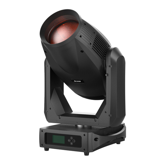
- Page 1 XP-5000WZ UserManual Please read the instruc on carefully before use...
-
Page 2: Table Of Contents
TABLE OF CONTENTS 1. Safety Instruction ....................2 2. Technical Specification ................... 3 3. Control Panel ......................5 4. Lamp ........................6 4.1 Lamp ......................... 6 4.2 Change The Lamp ..................7 5. How To Set The Unit ....................8 5.1 Main Function .................... -
Page 3: Safety Instruction
1. Safety Instruction Please read the instruction manual carefully which includes important information about the installation, usage and maintenance. WARNING Please keep this User Manual for future consultation. If you sell the unit to another user, be sure that they also receive this instruction manual. Important: Damages caused by the disregard of this user manual are not subject to warranty. -
Page 4: Technical Specification
Do not operate in dirty or dusty environment; do clean the fixture regularly. Do not touch any wire during operation as there might be a hazard of electric shock. Avoid power wires twist other cables. The minimum distance between light output and the illuminated surface must be more than 12 ... - Page 5 Display: LCD display (Battery backup for user operation without connecting to the mains) Optical system: High efficient Optical system. Delivering extremely powerful output. High quality lens. Movement: Pan: 540° Tilt: 270° Pan/Tilt Resolution: 16 bit Fixation: Pan/Tilt lock ...
-
Page 6: Control Panel
Photometrics Diagram Distance(m) 。 。 。 10Lux 115000 28000 12500 6800 Diameter(m) 1.05 3.15 。 70Lux 2400 Diameter(m) 6.37 12.74 19.11 25.48 3. Control Panel Front View Rear View 2 3 4 5 6 7 1. FUNCTION DISPLAY: Shows the various menus and the selected functions; 2. -
Page 7: Lamp
7. POWER: Connect to the mains supply; 8. POWER SWITCH: Turns On/Off the power; 4. Lamp 4.1 Lamp Osram Lok-it1400W/PS Brilliant: Because of its high internal pressure, there might be a risk that the Discharge lamp would explode during operation. The lamp emits intense UV radiation which is harmful to the eyes and skin. The high luminance of the arc can cause severe damage to the retina if you take a close look at the lamp. -
Page 8: Change The Lamp
4.2 Change The Lamp Loosen the screw at the rear side of the fixture and open the lamp compartment cover. Remove the old lamp and turn the lamp left in order to take the lamp out, put a new lamp that must be the same type as the old one. -
Page 9: How To Set The Unit
the lamp right in order to fix. Finally reinstall the lamp compartment cover, fastening it securely before turning on power. 5. How To Set The Unit 5.1 Main Function Turn on the unit, press the MENU button into menu mode, and press the UP/DOWN button until the required function is shown on the monitor. - Page 11 DMX Settings To select DMX Settings, press the ENTER button to confirm, use the UP/DOWN button to select DMX Address, Channel Mode, Connect To, Device ID、IP Address、Art-Net Setting、DMX Retransmit or View DMX Value. DMX Address To select DMX Address, press the ENTER button to confirm. Use the UP/DOWN button to adjust the address from 1 to 512, press the ENTER button to store.
- Page 12 16 Channel, 21 Channel or 21 Channel mode, press the ENTER button to store. Press the MENU button back to the last menu or let the unit idle one minute to exit menu mode. Connect To To select Connect To, press the ENTER button to confirm. Use the UP/DOWN button to select Auto, DMX or Ethernet, press the ENTER button to store.
- Page 13 Inverse, Tile Inverse, P/T Feedback, P/T Speed, BL.O. P/T Moving, BL.O. Color Change or Dimmer Curve. Pan Inverse To select Pan Inverse, press the ENTER button to confirm. Use the UP/DOWN button to select No (normal) or Yes (pan inverse), press the ENTER button to store. Press the MENU button back to the last menu or let the unit idle one minute to exit menu mode.
- Page 14 Dimmer Curve To select Dimmer Curve, press the ENTER button to show the DIMMER CURVE on the display, use the UP/DOWN button to select Square Law, Inverse Squ. Linear,or S-curve. Once selected, press the ENTER button to store. Press the MENU button back to the last menu or let the unit idle one minute to exit menu mode.
- Page 15 menu or let the unit idle one minute to exit menu mode. Display Settings To select Display Settings, press the ENTER button to confirm, use the UP/DOWN button to select Display Inverse, Backlight Intensity or Temperature Unit. Display Inverse To select Display Inverse, press the ENTER button to confirm. Use the UP/DOWN button to select No (normal) or Yes (display inverse), press the ENTER button to store.
- Page 16 Manual Test To select Manual Test, press the ENTER button to confirm, the present channel will show on the display, use the UP/DOWN button to select channel, press the ENTER button to confirm, then use the UP/DOWN button to adjust the value, press the ENTER button to store, the fixture will run as the channel value indicates.
-
Page 17: Home Position Adjustment
Reset Functions To select Reset Function, press the ENTER button to confirm, use the UP/DOWN button to select Pan/Tilt, Effect or All. Pan/Tilt —Reset Pan/Tilt To select Pan/Tilt, press the ENTER button to confirm, use the UP/DOWN button to select Yes (the unit will run built-in program to reset pan and tilt to their home positions) or No, press the ENTER button to store. - Page 18 the last menu. Press the MENU button to exit. Encoder Calibrate- Encoder Calibrate home position adjustment Enter offset mode, select Encoder Calibrate, press the ENTER button to confirm. Use the UP/DOWN button to offset the Encoder Calibrate, press the ENTER button to store. Press the MENU button to exit.
- Page 19 Shutter - Shutter home position adjustment Enter offset mode, select Shutter, press the ENTER button to confirm. Use the UP/DOWN button to offset the value from 0 to 255, press the ENTER button to store. Press the MENU button to exit. Dimmer - Dimmer home position adjustment Enter offset mode, select Dimmer, press the ENTER button to confirm.
-
Page 20: Error Information
offset the value from 0 to 255, press the ENTER button to store. Press the MENU button to exit. Yellow - Yellow home position adjustment Enter offset mode, select Yellow press the ENTER button to confirm. Use the UP/DOWN button to offset the value from 0 to 255, press the ENTER button to store. -
Page 21: Control By Universal Dmx Controller
They appear when board P.C or some wires are damaged. Pan Reset Error, Pan Encode Error, Tilt Reset Error, Tilt Encode Error, Shutter Reset Fail, Dimmer Reset Fail, Color Reset Fail, , Gobo Reset Fail, Focus Reset fail. They may appear when turning on or resetting the unit, for some parts such as board P.C are damaged. Please contact the qualified maintenance. -
Page 22: Channel Mode Setting
the units’ power is disconnected. 4. Each lighting unit needs to have a DMX address to receive the data by the controller. The address number is between 0-511 (usually 0 & 1 are equal to 1). 5. The end of the DMX 512 system should be terminated to reduce signal errors. 6. -
Page 23: Dmx Control
6.4 DMX Control 16Channels (Mode 1): CHANNEL VALUE FUNCTION PAN: 0 – 255 0° 540° 0 – 255 PAN FINE TILT: 0 – 255 0° 270° 0 – 255 TILT FINE PAN/TILT SPEED 0 – 255 Fast Slow STROBE: 000 –... - Page 24 212-217 stop 218-243 CCW Rotation: Slow Fast 244-247 Random color: Fast 248-251 Random color: Medium 252-255 Random color: Slow COLOR 2 Open 001-014 Open to Color 1 Color 1 016-029 Color 1 Color 2 Color 2 031-044 Color 2 Color 3 Color 3 046-059 Color 3...
- Page 25 064-085 Color 4 086-106 Color 5 107-127 Color 6 128-148 Color 7 149-170 Color 8 171-191 Color 9 192-212 Color 10 213-233 Color 11 234-255 Color 12 ZOOM: 0 – 255 Wide narrow FUNCTION: 000 – 069 No Function 070 –...
- Page 26 197 – 202 Random Pulse Close Fast to Slow 203 – 207 Open 208 – 217 Reset 218 – 227 Open 228 – 237 Lamp On 238 – 247 Open 248 – 255 Lamp Off DIMMER: 0 – 255 Closed (0% ) Open (100%) CYAN: 0 –...
- Page 27 Null Null Null Null Null PAN: 0 – 255 0° 540° 0 – 255 PAN FINE TILT: 0 – 255 0° 270° 0 – 255 TILT FINE PAN/TILT SPEED 0 – 255 Fast Slow Null 21 Channels (Mode 3): CHANNEL VALUE FUNCTION...
- Page 28 150 – 159 Effect Reset 160 – 169 No Function 170 – 189 Effect Reset 190 – 199 No Function 200 – 209 Reset All 210 – 229 No Function 230 – 239 Lamp Off 240 – 255 No Function PAN/TILT MACRO 000 –...
- Page 29 Color 1 016-029 Color 1 Color 2 Color 2 031-044 Color 2 Color 3 Color 3 046-059 Color 3 Color 4 Color 4 061-074 Color 4 Color 5 Color 5 076-089 Color 5 Color 6 Color 6 091-104 Color 6 Open 105-140 Open 141-145...
- Page 30 166-170 Color 6 171-185 Open 186-211 CW Rotation: Fast Slow 212-217 stop 218-243 CCW Rotation: Slow Fast 244-247 Random color: Fast 248-251 Random color: Medium 252-255 Random color: Slow CYAN: 0 – 255 0% 100% MAGENTA: 0 – 255 0% ...
-
Page 31: Troubleshooting
ZOOM: 0 – 255 Wide narrow STROBE: 0 – 19 Shutter closed, lamp switches to low power 20 – 49 Shutter Open 50 – 200 Strobe, slow fast 201 – 210 Shutter Open 211 – 255 Random strobe DIMMER: 0 –... - Page 32 D. The lamp is cutting out intermittently 1. The lamp is not working well. Check the mains voltage either too high or too low. 2. Internal temperature may be too high. Check if replacement of fan is needed on the head. E.
-
Page 33: Check、 Cleaning And Maintenance Schedule
8. Check、 Cleaning and Maintenance Schedule Check: Ballast A. Do check the fixtures every two months and make sure that all the screws and terminals have been locked firmly to make sure the normal performance of the fixtures. Negligence of check would cause malfunction of the fixture. - Page 34 damp, smoky or particularly dirty surrounding can cause greater accumulation of dirt on the unit’s optics. Clean with soft cloth and use normal glass to clean liquid. Always dry the parts carefully. Clean the external optics at least every 20 days. Clean the internal optics at least every 30/60 days. Maintenance Schedule: To make sure that the fixture is running well and has less failures and higher performance, longer life time, safer running, the fixture should be checked and maintained periodically.
- Page 35 Declaration of Conformity We declare that our products (lighting equipments) comply with the following specification and bears CE mark in accordance with the provision of the Electromagnetic Compatibility (EMC) Directive 89/336/EEC. EN55103-1: 2009 ; EN55103-2: 2009; EN62471: 2008; EN61000-3-2: 2006 + A1:2009 + A2:2009; EN61000-3-3: 2008. &...
- Page 36 Innovation, Quality, Performance...
Need help?
Do you have a question about the XP-5000WZ and is the answer not in the manual?
Questions and answers