Table of Contents
Advertisement
Quick Links
Advertisement
Table of Contents

Related Manuals for ACME SUPERNOVA


Summary of Contents for ACME SUPERNOVA
-
Page 2: Table Of Contents
CONTENTS 01/ Safety Information ....................2 02/ Technical Specifications ..................6 03/ Overview ........................8 04/ Connecting Power and Data ................9 4.1 Connecting Power ................... 9 4.2 Connecting Data.................... 10 05/ Fixture Installation ....................11 06/ Effect Wheels ......................13 07/ Operation ....................... -
Page 3: 01/ Safety Information
01/ Safety Information Please read the instruction carefully which includes important information about the installation, usage and maintenance. WARNING Please keep this User Guide for future consultation. If you sell the unit to another user, be sure that they also receive this instruction manual. Important: Damages caused by the disregard of this user manual are not subject to warranty. - Page 4 off the mains power immediately. DO NOT operate in a dirty or dusty environment. DO clean the fixture regularly. DO NOT touch any wire during operation as there might be a hazard of electric shock. Avoid entanglement of the power cord with other wires. ...
- Page 5 01/ Consignes de sécurité Veuillez lire attentivement les instructions qui contiennent des informations importantes sur l'installation, l'utilisation et l'entretien. ATTENTION Veuillez conserver ce guide de l'utilisateur pour une consultation future. Si vous vendez l'appareil à un autre utilisateur, assurez-vous qu'il reçoive également ce manuel d'instructions.
- Page 6 Assurez-vous que le cordon d'alimentation n'est pas pincé ou endommagé; remplacez-le immédiatement s'il est endommagé. La température de surface de l'unité peut atteindre 70℃. NE PAS toucher les capots à mains nues pendant son fonctionnement. Évitez que des liquides inflammables, de l'eau ou du métal ne pénètrent dans l'appareil. Si ...
-
Page 7: 02/ Technical Specifications
02/ Technical Specifications AC Power 180-240V~ 50/60Hz Max. Power 2265W Consumption Light Source SCL1800YF-80-R72 Color Temperature 6700K Zoom Range 4°-48° Color Wheel 1 5 colors + open Color Wheel Color Wheel 2 2 colors + CTB + CRI + open Rotating Gobo Wheel 1 6 replaceable gobos + open Gobo Wheel... - Page 8 Variable color temperature control Animation wheel: continuous rotation with variable speed and direction Iris: Variable 0-100% Prisms: two indexing/rotating prisms (4-facet circular prism and 4-facet linear prism) Frost: soft frost effect and heavy frost effect Motorized zoom Motorized focus Framing: rotatable framing module, +/-60°, 4 x individually controllable full framing blades with variable angle and position Power Cable with Neutrik true1 power connector Included Items...
-
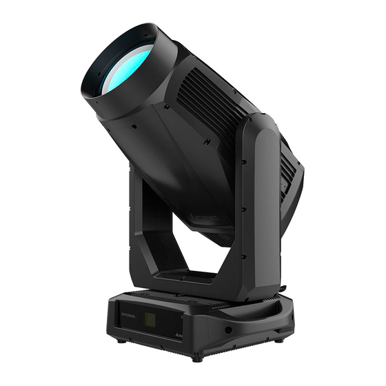
Page 9: 03/ Overview
03/ Overview 1. Display To show the various menus and the selected function MENU To enter into move backward or leave the menu UP To go backward to move up in the menu 2. Buttons DOWN To go forward to move down in the menu ENTER To perform the desired functions 3. -
Page 10: 04/ Connecting Power And Data
04/ Connecting Power and Data 4.1 Connecting Power To apply power, first check that the head pan and tilt locks are released. This fixture can operate on any 180-240V~ 50/60Hz AC mains power supply. The maximum power consumption is 2265W. The fixture must be grounded/earthed and able to be isolated from AC power. -
Page 11: Connecting Data
4.2 Connecting Data The fixture is equipped with 5-pin (or 3-pin) XLR sockets for DMX input and output. Use a high-quality DMX cable designed for RS-485 and 5-pin (or 3-pin) XLR-plugs and connectors in order to connect the controller with the fixture or one fixture with another. For outdoor installations, use only IP-rated XLR connectors suitable for outdoor use. -
Page 12: 05/ Fixture Installation
05/ Fixture Installation The fixture is IP66-rated and designed for both indoor and outdoor events. This means that it is protected from: Dust, to the degree that dust cannot enter the device in sufficient quantities as to interfere with its operation. ... - Page 13 Steps for installing omega brackets to the fixture: - 12 -...
-
Page 14: 06/ Effect Wheels
06/ Effect Wheels DANGER! Replace the rotating gobos with the device switched off only. Unplug from mains before replacing the rotating gobos! - 13 -... - Page 15 Rotating Gobo Wheel 1 Rotating Gobo Wheel 2 Slot Name Part Number Slot Name Part Number Open Empty Open Empty Broken Circle 3011001474 Square Tunnel 3011001481 Eccentric Circles 3011001475 Clouds 3011001482 Dream Tunnel 3011001476 Mixed Beams 3011001483 Tiny Bubbles 3011001477 Multiple Angles 3011001484 Square Bar...
-
Page 16: 07/ Operation
07/ Operation 7.1 Control Menu To access the control menus, press the [MENU] button. Navigate the menu structure, using the [ENTER], [ UP] and [ DOWN] buttons. To select a menu option or to confirm a selection, press the [ENTER] button. ... - Page 17 MAIN MENU SUBMENU CHOICES/VALUES Universe 1-32000 (Default=1) sACN Settings Priority 0-200 (Default=100) Network to DMX Pan Invert Tilt Invert P/T Feedback Fast Dimmer Speed Smooth Linear Square Law Dimmer Curve Inv SQ Law S Curve Standard Cooling Mode Quiet Theatre Bright Calibration 50-100 (Default=100)
- Page 18 MAIN MENU SUBMENU CHOICES/VALUES Enable Color Short Cut Disable Display Invert Backlight Intensity 1-10 (Default=10) Display Settings °C Temperature Unit °F English Language Chinese Single Auto Test Cycle Clear No/Yes 0-255 Tilt 0-255 0-255 Cyan 0-255 Magenta 0-255 Yellow 0-255 0-255 Color 1 0-255...
- Page 19 MAIN MENU SUBMENU CHOICES/VALUES Blade DW 2 0-255 Blade UP 1 0-255 Blade UP 2 0-255 Blade LF 1 0-255 Blade LF 2 0-255 Blade RG 1 0-255 Blade RG 2 0-255 Fixture Use Hour Total LED Hour LED Use Hour LED On Hour LED Hours Reset Password=050...
- Page 20 DMX Settings Enter the control menu and select DMX Settings, press ENTER. Use the UP/DOWN button to select DMX Address, DMX Channel Mode, No DMX Status, View DMX Value, Connect Option, Network, Art-Net Settings, sACN Settings or Network to DMX. DMX Address Select DMX Address, press ENTER.
- Page 21 View DMX Value Select View DMX Value, press ENTER. Use UP/DOWN button to select the desired DMX channel, for which the value is to be displayed. To exit the menu, press MENU, or wait 30 seconds. Connect Option Select Connect Option, press ENTER. Use UP/DOWN button to select Auto, DMX, Art-Net or sACN, confirm your selection with ENTER.
- Page 22 Fixture Settings Enter the control menu and select Fixture Settings, press ENTER. Use the UP/DOWN button to select Pan Invert, Tilt Invert, P/T Feedback, Dimmer Speed, Dimmer Curve, Cooling Mode, Bright Calibration, Blade Mode, Led Refresh Rate, Gobo Short Cut or Color Short Cut. Pan Invert Select Pan Invert, press ENTER.
- Page 23 Dimmer Curve Select Dimmer Curve, press ENTER. Use UP/DOWN button to select Linear, Square Law, Inv SQ Law or S Curve, confirm your selection with ENTER. To exit the menu, press MENU, or wait 30 seconds. Cooling Mode Select Cooling Mode, press ENTER. Use UP/DOWN button to select Standard, Quiet or Theatre, confirm your selection with ENTER.
- Page 24 Led Refresh Rate Select Led Refresh Rate, press ENTER. Use UP/DOWN button to select 900Hz, 1000Hz, 1100Hz, 1200Hz, 1300Hz, 1400Hz, 1500Hz, 2500Hz, 4000Hz, 5000Hz, 6000Hz, 10KHz, 15KHz, 20KHz or 25KHz, confirm your selection with ENTER. To exit the menu, press MENU, or wait 30 seconds. Gobo Short Cut Select Gobo Short Cut, press ENTER.
- Page 25 Display Settings Enter the control menu and select Display Settings, press ENTER. Use the UP/DOWN button to select Display Invert, Backlight Intensity, Temperature Unit or Language. Display Invert Select Display Invert, press ENTER. Use UP/DOWN button to select No (display normal) or Yes (display inverted), confirm your selection with ENTER.
- Page 26 Fixture Test Enter the control menu and select Fixture Test, press ENTER. Use the UP/DOWN button to select Auto Test or Manual Test. Auto Test Select Auto Test, press ENTER. Use UP/DOWN button to select Single (the device immediately performs a single automatic self-test) or Cycle (the device immediately performs a cyclic automatic self-test), confirm your selection with ENTER.
- Page 27 LED Use Hour Select LED Use Hour, press ENTER. Use UP/DOWN button to select Total LED Hour (total time) or LED On Hour (current switch-on time), confirm your selection with ENTER. The total time or current switch-on time is displayed. Use UP/DOWN button to select LED Hours Reset, confirm your selection with ENTER.
- Page 28 Error Logs Select Error Logs, press ENTER. Use UP/DOWN button to select Fixture Errors, confirm your selection with ENTER. The error list is displayed. Use UP/DOWN button to select Reset Error Log, confirm your selection with ENTER. If you wish to reset the relevant error logs, select Yes. If you do not wish to reset anything, select No.
- Page 29 All Reset Select All Reset, press ENTER. Use UP/DOWN button to select No or Yes (the device will run built-in program to reset all to their home positions), confirm your selection with ENTER. To exit the menu, press MENU, or wait 30 seconds. Special Function Enter the control menu and select Special Function, press ENTER.
- Page 30 Firmware Restore Select Firmware Restore, press ENTER. If you wish to restore fixture’s firmware, select Yes. Once Yes is selected, the display will show “Upgrading, Please Wait...”. A percentage bar will also be displayed. After the update is complete, the fixture will perform a reset (this can take some time).
-
Page 31: Updating Software
7.2 Updating Software Only qualified technicians should perform this function! Note all menu settings before updating software! Please note, up to 32 fixtures can be connected together and updated at the same time. Note: Before using the USB flash drive to update the software, please ensure that the USB flash drive is formatted with the FAT32 file system. - Page 32 Updating Software: 1. Download the software update files from the ACME website. 2. Copy the software files to a compatible USB flash drive. Note: To avoid the risk of uploading the wrong file to the fixture, make sure that there are no other files on your flash drive.
- Page 33 RDM functions: Certain menus of the device and functions can be called up via the RDM protocol. The parameter IDs are implemented as follows for different commands: Command Command Command Parameter ID ‘Discovery’ ‘Set’ ‘Get’ DISC_UNIQUE_BRANCH √ DISC_MUTE √ DISC_UN_MUTE √...
-
Page 34: Home Position Adjustment
7.3 Home Position Adjustment To access the control menus, press the [MENU] button. To access the offset menus, long-press the [ENTER] button. Navigate the offset menus, using the [ENTER], [ UP] and [ DOWN] buttons. To select a menu option or to confirm a selection, press the [ENTER] button. ... - Page 35 Focus -128~127 Blade -128~127 Blade DW 1 -128~127 Blade DW 2 -128~127 Blade UP 1 -128~127 Blade UP 2 -128~127 Blade LF 1 -128~127 Blade LF 2 -128~127 Blade RG 1 -128~127 Blade RG 2 -128~127 Frequency(Hz) Select Frequency(Hz), press ENTER. Use UP/DOWN button to select a value, confirm your selection with ENTER.
- Page 36 Dimming Start Select Dimming Start, press ENTER. Use UP/DOWN button to select a value between 0 and 9999, confirm your selection with ENTER. To exit the offset menu, press MENU, or wait 30 seconds. Dim 1 Offset Select Dim 1 Offset, press ENTER. Use UP/DOWN button to select a value between -128 and 127, confirm your selection with ENTER.
- Page 37 Cyan Select Cyan, press ENTER. Use UP/DOWN button to select a value between -128 and 127, confirm your selection with ENTER. To exit the offset menu, press MENU, or wait 30 seconds. Magenta Select Magenta, press ENTER. Use UP/DOWN button to select a value between -128 and 127, confirm your selection with ENTER.
- Page 38 Gobo 1 Select Gobo 1, press ENTER. Use UP/DOWN button to select a value between -128 and 127, confirm your selection with ENTER. To exit the offset menu, press MENU, or wait 30 seconds. R-Gobo 1 Select R-Gobo 1, press ENTER. Use UP/DOWN button to select a value between -128 and 127, confirm your selection with ENTER.
- Page 39 Prism 1 Select Prism 1, press ENTER. Use UP/DOWN button to select a value between -128 and 127, confirm your selection with ENTER. To exit the offset menu, press MENU, or wait 30 seconds. R-Prism 1 Select R-Prism 1, press ENTER. Use UP/DOWN button to select a value between -128 and 127, confirm your selection with ENTER.
- Page 40 Zoom Select Zoom, press ENTER. Use UP/DOWN button to select a value between -128 and 127, confirm your selection with ENTER. To exit the offset menu, press MENU, or wait 30 seconds. Focus Select Focus, press ENTER. Use UP/DOWN button to select a value between -128 and 127, confirm your selection with ENTER.
- Page 41 Blade UP 2 Select Blade UP 2, press ENTER. Use UP/DOWN button to select a value between -128 and 127, confirm your selection with ENTER. To exit the offset menu, press MENU, or wait 30 seconds. Blade LF 1 Select Blade LF 1, press ENTER. Use UP/DOWN button to select a value between -128 and 127, confirm your selection with ENTER.
-
Page 42: 08/ Configuring The Device For Dmx Control
08/ Configuring the Device for DMX Control 8.1 Address Setting All fixtures should be given a DMX starting address when operating with a DMX controller, in order to ensure that the correct fixture responds to the correct control signal. Incorrect settings will result in unpredictable responses from the lighting controller. -
Page 43: Dmx Protocol
8.2 DMX Protocol CHANNEL VALUE FUNCTION 43ch 34ch 32ch 23ch 0°540° 000-255 000-255 PAN FINE TILT 000-255 0°270° 000-255 TILT FINE PAN/TILT SPEED 000-255 Fast to Slow 000-007 Close 008-255 Open CYAN 000-255 0%100% MAGENTA 000-255 0%100% YELLOW 000-255 0%100% 000-255 0%100% COLOR WHEEL 1... - Page 44 128-189 Counter-Clockwise Rotation, Fast to Slow 190-193 Stop 194-255 Clockwise Rotation, Slow to Fast COLOR WHEEL 2 000-007 Open 008-021 022-035 Color 1 036-048 Color 2 049-063 Reserved 064-069 Open 070-075 Open + CTB 076-081 082-087 CTB + Color 1 088-093 Color 1 094-099...
- Page 45 GOBO WHEEL 2 000-007 Open 008-016 Gobo 1 017-025 Gobo 2 026-034 Gobo 3 035-043 Gobo 4 044-052 Gobo 5 053-063 Gobo 6 064-073 Gobo 1 Shaking, Slow to Fast 074-083 Gobo 2 Shaking, Slow to Fast 084-093 Gobo 3 Shaking, Slow to Fast 094-103 Gobo 4 Shaking, Slow to Fast 104-113...
- Page 46 194-255 Counter-Clockwise Rotation, Slow to Fast FROST 1 (Soft) 000-255 0%100% FROST 2 (Heavy) 0%100% 000-255 ZOOM 000-255 WideNarrow 000-255 ZOOM FINE FOCUS 000-255 0%100% 000-255 FOCUS FINE STROBE 000-007 Close 008-015 Open 016-131 Strobe from Slow to Fast 132-139 Open 140-181 Fast Open Slow Close from Slow to Fast...
- Page 47 FUNCTION (To activate following functions, stop in DMX value for at least 3 seconds.) 000-005 Null 006-007 Null 008-009 Null 010-019 Blade Mode: Mode 1 (Not available on 34ch & 23ch) 020-029 Blade Mode: Mode 2 (Not available on 34ch & 23ch) 030-039 Dimmer Curve Square Law 040-049...
-
Page 48: 09/ Error Information
09/ Error Information Error codes are shown continuously in the display when the fixture fails and they will not disappear until the fixture is repaired. CPU-B/C/D/E/F/G Error Check whether the 485 (DATA) leads on the PCB board are installed in place or disconnected. - Page 49 Tilt Reset Error Check whether the position of the tilt where the magnet is installed falls off or is damaged. Check whether there are obstacles in the tilt operating range. Check whether the Hall element on the tilt is damaged. Check whether the lead connecting the Hall element on the tilt and the PCB board is in poor contact or disconnected.
- Page 50 Cyan Reset Error Check whether the position of the cyan color wheel where the magnet is installed falls off or is damaged. Check whether there are obstacles in the cyan color wheel operating range. Check whether the Hall element on the cyan color wheel is damaged. Check whether the lead connecting the Hall element on the cyan color wheel and the PCB board is in poor contact or disconnected.
- Page 51 Yellow Reset Error Check whether the position of the yellow color wheel where the magnet is installed falls off or is damaged. Check whether there are obstacles in the yellow color wheel operating range. Check whether the Hall element on the yellow color wheel is damaged.
- Page 52 Color 1/2 Reset Error Check whether the position of the color wheel 1/2 where the magnet is installed falls off or is damaged. Check whether there are obstacles in the color wheel 1/2 operating range. Check whether the Hall element on the color wheel 1/2 is damaged. Check whether the lead connecting the Hall element on the color wheel 1/2 and the PCB board is in poor contact or disconnected.
- Page 53 R-Gobo 1/2 Reset Error Check whether the position of the gobo wheel 1/2 where the magnet is installed falls off or is damaged. Check whether there are obstacles in the gobo wheel 1/2 operating range. Check whether the Hall element on the gobo wheel 1/2 is damaged. Check whether the lead connecting the Hall element on the gobo wheel 1/2 and the PCB board is in poor contact or disconnected.
- Page 54 Prism 1/2 Reset Error Check whether the position of the prism 1/2 where the magnet is installed falls off or is damaged. Check whether there are obstacles in the prism 1/2 operating range. Check whether the Hall element on the prism 1/2 is damaged. Check whether the lead connecting the Hall element on the prism 1/2 and the PCB board is in poor contact or disconnected.
- Page 55 Focus Reset Error Check whether the position of the focus where the magnet is installed falls off or is damaged. Check whether there are obstacles in the focus operating range. Check whether the Hall element on the focus is damaged. Check whether the lead connecting the Hall element on the focus and the PCB board is in poor contact or disconnected.
- Page 56 Blade Reset Error Check whether the position of the blade where the magnet is installed falls off or is damaged. Check whether there are obstacles in the blade operating range. Check whether the Hall element on the blade is damaged. Check whether the lead connecting the Hall element on the blade and the PCB board is in poor contact or disconnected.
- Page 57 Head Fan1/2/3/4/5/6/7/8/9/10/11 Start Err Check whether the fan is not running. Check whether the fan leads are installed in place or disconnected. Check whether the fan is damaged. Check whether there are obstacles in the fan operating range. Head Fan1/2/3/4/5/6/7/8/9/10/11 Stop Err Check whether the fan circuit on the motherboard breaks down.
- Page 58 Base Humi. Too High Disassemble the housing of the fixture to dehumidify. Head Humidity Error Check whether the humidity sensor is faulty. Check whether the lead connecting the humidity sensor is installed in place or disconnected. Base Humidity Error Check whether the humidity sensor is faulty. Check whether the lead connecting the humidity sensor is installed in place or disconnected.
-
Page 59: 10/ Troubleshooting
10/ Troubleshooting Problem Potential cause(s) Remedies Confirm that the power is switched No power to the fixture. Fixture does not respond on and cables are plugged in. or appears to be off. No output from PSU. Replace the PSU. Fixture suddenly turned Check the power supply, switches Power was turned off. -
Page 60: 11/ Fixture Cleaning
11/ Fixture Cleaning Regular cleaning is very important for fixture life and performance. Buildup of dust, dirt, smoke particles, fog fluid residues, etc. degrades the fixture’s light output and cooling ability. Cleaning schedules for lighting fixtures vary greatly depending on the operating environment. It is therefore impossible to specify precise cleaning intervals for the fixture. -
Page 61: 12/ Approvals And Certifications
12/ Approvals and Certifications This product has been tested and found to comply with the following standards: - 2014/30/EU - Electromagnetic Compatibility (EMC) - 2014/35/EU - Low Voltage Directive (LVD) - cETLus Approved (Control #5000057) - UK SI 2016 No. 1091: Electromagnetic Compatibility Regulations 2016 - UK SI 2016 No.
Need help?
Do you have a question about the SUPERNOVA and is the answer not in the manual?
Questions and answers