
Subscribe to Our Youtube Channel
Related Manuals for Ametek dunkermotoren BG 95x40 dPro CO


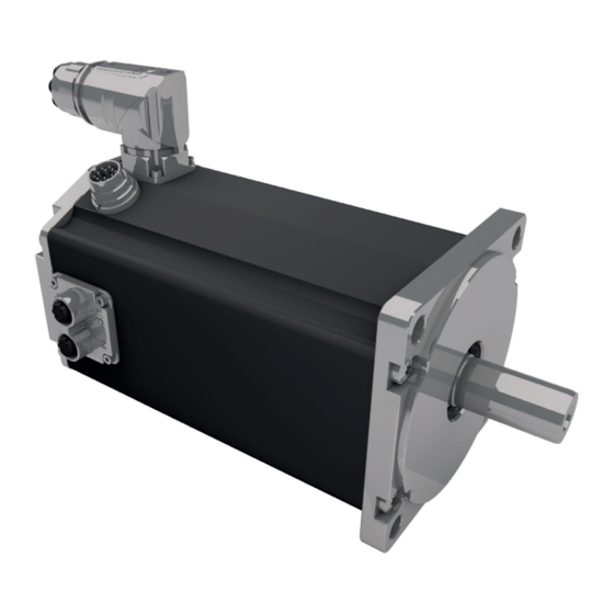
Summary of Contents for Ametek dunkermotoren BG 95x40 dPro CO
- Page 1 Original Funktions- und Anschlussbeschreibung/ Translation of the original function and connection guide BG 95 dPro CO/IO/PN/EC/EI Typ: Part No: BG 95x40 dPro 88595 05XXX BG 95x80 dPro 88595 06XXX BG 95x120 dPro 88595 07XXX...
-
Page 2: Table Of Contents
Content Inhalt 1. About this Documentation ....5 1. Zu dieser Dokumentation...... 5 Liability and Warranty .......... 6 Haftung und Gewährleistung ....... 6 Target Group ............6 Zielgruppe ............6 Safety Notes ............6 Sicherheitshinweise ..........6 Icons ..............7 Piktogramme ............ - Page 3 Functions ............17 Funktionen ............17 Type of control CANopen dPro CO....18 Ansteuerungsvariante CANopen dPro CO ..18 Type of control PROFINET dPro PN ....20 Ansteuerungsvariante PROFINET dPro PN ..20 Type of control EtherCat dPro EC ...... 21 Ansteuerungsvariante EtherCat dPro EC ...
- Page 4 and BG 95x48/60V Motors ....... 46 BG 95x48/60V Motoren ........46 EMC compliant installation ........ 47 EMV-konforme Installation ......... 47 6.3.1 Functional Earth ..........48 6.3.1 Funktionserde ........... 48 6.3.2 Protective Earth Conductor ....... 48 6.3.2 Schutzleiter ............48 Protective Grounding ........48 Schutzerdung ...........
-
Page 5: About This Documentation
About this Documentation Zu dieser Dokumentation This documentation is targeted at people who are Diese Dokumentation richtet sich an Personen, die mit charged with transport, assembly and connection of the Transport, Montage und Anschluss des Motors beauftragt motor. sind. In the following, the BG 95 dPro is referred to as Im nachfolgenden wird der BG 95 dPro als „Produkt“... -
Page 6: Liability And Warranty
Liability and Warranty Haftung und Gewährleistung Dunkermotoren GmbH does not accept any liability or Die Dunkermotoren GmbH übernimmt keine Haftungs- warranty claims for personal injury or damage to property und Gewährleistungsansprüche für Personen- und Sach- if they are attributable to one or several of the following schäden, wenn sie auf einen oder mehrere der folgenden causes: Ursachen zurückzuführen sind:... -
Page 7: Icons
Piktogramme Icons This document uses the following icons: In diesem Dokument werden folgende Piktogramme ver- wendet: Symbol/ Meaning/ Symbol Bedeutung Observe operating instructions/ Gebrauchsanweisung beachten Earth before use/ Vor Benutzung erden Recommendations/ Empfehlungen Instruction to act/ Handlungsaufforderung Hazard Signs Gefahrenzeichen The hazard signs inform about potential hazards and Die Gefahrenzeichen weisen auf mögliche Gefahren hin name measures to avoid risks. -
Page 8: Ec/Eu Declaration Of Conformity
EC/EU Declaration of Conformity EG/EU-Konformitätserklärung With the EC/EU declaration of conformity, the manufac- Mit der EG-/EU-Konformitätserklärung bescheinigt der turer confirms that he has met all basic safety and health Hersteller, alle grundlegenden Sicherheits- und Gesund- requirements of of the applicable directive. heitsanforderungen der anzuwendenden Richtlinie erfüllt zu haben. -
Page 9: Safety Notes
Safety Notes Sicherheitshinweise The safety notes are only part of the technical documen- Die Sicherheitshinweise sind nur ein Teil der technischen tation of this product. They must be read in connection Dokumentation dieses Produkts. Sie sind im Zusammen- with the other technical documentation. hang mit den anderen technischen Dokumentationen zu sehen. -
Page 10: Basic Safety Notes
Basic Safety Notes Grundlegende Sicherheitshinweise Only use the product in an impeccable condition. Verwenden Sie das Produkt nur im einwandfreien Zustand. Observe the technical data and environmental condi- tions indicated in the documentation. Halten Sie die in der Dokumentation angegebenen technischen Daten und Umgebungsbedingungen ein. -
Page 11: Safety Notes Concerning Operating Phases
Safety Notes concerning Operating Phases Sicherheitshinweise zu Betriebsphasen 2.5.1 Transport 2.5.1 Transport Transport the product contoller only in its original Transportieren Sie das Produkt nur in der Originalver- packaging. packung. Ensure that the transported goods are sufficiently Sorgen Sie für ausreichende Sicherung des Transport- secured. -
Page 12: Maintenance/Repair
2.5.4 Maintenance/Repair 2.5.4 Wartung/Reparatur The product is maintenance-free during the intended Das Produkt ist über die vorhergesehene Lebensdauer service life. wartungsfrei. Observe the following safety instructions when carrying Bei Wartungsarbeiten an der Anlage sind die folgenden out maintenance work on the unit: Sicherheitshinweise zu beachten: Make sure that the product is only installed, Achten Sie darauf, dass das Produkt nur von ausgebil-... -
Page 13: Notes Concerning Special Hazard Types
Notes concerning Special Hazard Types Hinweise auf besondere Gefahrenarten 2.6.1 Electrical Energy/Electromagnetic 2.6.1 Elektrische Energie/elektromagnetische Safety Sicherheit Operation of the product or the entire equipment will Beim Betrieb des Produkts bzw. der gesamten Anlage produce electromagnetic interferences. These may influ- entstehen elektromagnetische Störungen. -
Page 14: Transport And Storage
Transport and Storage Transport und Lagerung Observe the environmental conditions during transport Beachten Sie bei Transport und Lagerung die Umge- and storage. If your storage and transport conditions bungsbedingungen. Falls Sie davon abweichende Lage- deviate from these (see table below), please contact us so rungs- und Transportbedingungen haben (siehe Tabelle that we can review potential impacts on your products. -
Page 15: Product Description
Product Description Produktbeschreibung Design Aufbau The BG 95 dPro motor series are brushless DC servo- » Bei der Motorbaureihe BG 95 dPro handelt es sich um » motors with integrated motion controllers. The com- bürstenlose DC-Servomotoren mit integriertem Moti- fortable PC operating interface makes it easy to set oncontroller und komfortabler Bedienoberfläche für drive parameters for a number of pre-installed basic PC, auf der sich die Antriebe für eine Reihe vorgefer-... -
Page 16: Starter Kit
Starter Kit Starter Kit The Starter Kit can be used in order to integrate a drive Um einen Antrieb bzw. externen Regler über einen PC in unit or external controller into a CANopen network as a ein CANopen-Netzwerk als Slave zu integrieren, kann das slave via a PC. -
Page 17: Functions
Functions Funktionen The product is available with dPro IO, dPro CO, dPro PN, Das Produkt ist mit dPro IO, dPro CO, dPro PN, dPro EC dPro EC and dPro EI functionality. Information on this is und dPro EI Funktionalität erhältlich. Informationen dazu available from Dunkermotoren. -
Page 18: Type Of Control Canopen Dpro Co
Type of control CANopen dPro CO Ansteuerungsvariante CANopen dPro CO The communication protocol CANopen supports you Das Kommunikationsprotokoll CANopen unterstützt Sie in linking complex devices. In addition to the network bei der Vernetzung komplexer Geräte. Neben dem Netz- management and device monitoring, communication werkmanagement und der Geräteüberwachung wird auch between various nodes is supported as well. - Page 19 CANopen interface CANopen – Schnittstelle Profile Position Mode (CiA 402 Mode 1) Profile Position Mode (CiA 402 Mode 1) The „Profile Position Mode“ serves positioning from a start Der "Profile Position Mode" dient der Positionierung von to a target point. Positioning takes place with reference to einem Start- zu einem Zielpunkt.
-
Page 20: Type Of Control Profinet Dpro Pn
Type of control PROFINET dPro PN Ansteuerungsvariante PROFINET dPro PN Products operation in Profinet networks. They are IRT- Produkte mit dPro PN Funktionalität sind für den Betrieb capable and can be controlled by control systems from in Profinet Netzwerken vorgesehen. Sie sind IRT fähig und various manufacturers, e.g. -
Page 21: Type Of Control Ethercat Dpro Ec
Type of control EtherCat dPro EC Ansteuerungsvariante EtherCat dPro EC Products with dPro EC functionality are designed for Produkte mit dPro EC Funktionalität sind für den Betrieb operation in EtherCAT networks. They support distributed in EtherCAT Netzwerken vorgesehen. Sie unterstützen Clocks and can be controlled by different manufacturer‘s Distributed Clocks und können von Steuerungen unter- controllers, e.g. -
Page 22: Type Of Control Ethernet/Ip Dpro Ei
Type of control EtherNet/IP dPro EI Ansteuerungsvariante EtherNet/IP dPro EI Products with dPro EI functionality are intended for ope- Produkte mit dPro EI Funktionalität sind für den Betrieb ration in EtherNet/IP networks. They are certified by the in EtherNet/IP Netzwerken vorgesehen. Sie sind von der ODVA and can be controlled by controllers from different ODVA zertifiziert und können von Steuerungen unter- manufacturers, e.g. -
Page 23: Type Of Control Dpro Io
4.10 Type of control dPro IO 4.10 Ansteuerungsvariante dPro IO In IO mode, the product can be operated ‚stand-alone‘. Im IO Modus kann das Produkt ‚stand-alone‘ betrieben The product is then controlled via digital or analogue In- werden. Angesteuert wird das Produkt dann über digitale puts. -
Page 24: Protective Functions
4.11 Protective Functions 4.11 Schutzfunktionen The product has various protection functions to avoid da- Das Produkt besitzt verschiedene Schutzfunktionen, um mage from overload. Each of these protection functions is Schäden durch Überbelastung zu vermeiden. Jede dieser described in detail below. The output stage switches off Schutzfunktionen wird nachfolgend im Detail beschrieben. -
Page 25: Current Limitation (I T)
4.11.4 Current Limitation (I 4.11.4 Strombegrenzung (I The products is protected from thermal overload by an Die Produkte sind durch einen I²t-basierten Algorithmus I²t-based algorithm. It calculates the heat supply caused gegen thermische Überlastung geschützt. Er berechnet by the phase current and limits the nominal current if die durch den Phasenstrom verursachte Wärmezufuhr the calculated product temperature exceeds the critical und begrenzt den Sollstrom, wenn die berechnete Tem-... - Page 26 Current characteristics Stromkennlinien For internal use only! For internal use only! Overload Characteristics (I²t) BG 95x40, 24V Overload Characteristics (I²t) BG 95x80, 24V 1000 1000 Motor Motor Temp [°C] Temp [°C] Phase Current [A] Phase Current [A] For internal use only! For internal use only! Overload Characteristics (I²t) BG 95x40, 48V Overload Characteristics (I²t) BG 95x80, 48V...
-
Page 27: 4.11.5 Ballast Circuit
4.11.5 Ballast Circuit 4.11.5 Ballastschaltung The drive unit has a 4-quadrant control. Therefore, it can Der Antrieb besitzt eine 4-Quadranten Regelung, deshalb also work as a generator. During deceleration, the rotating kann er auch als Generator arbeiten. Beim Bremsen wird energy on the drive shaft is converted and fed back into die an der Antriebswelle vorhandene Energie umgewan- the power supply. -
Page 28: Voltage Controlled Braking
4.11.7 Voltage Controlled Braking 4.11.6 Spannungsgeregeltes Bremsen When the drive is actively braked, electrical energy flows Beim aktiven Abbremsen des Antriebes fließt elektrische back into the power supply. If this energy cannot be Energie zurück in die Stromversorgung. Kann diese absorbed, the voltage rises. -
Page 29: Technical Data
Technical Data Technische Daten Produktspezifikation Product specification More information on the drive behavi- Mehr Informationen zum Antriebsver- or can be found in the configurator at halten finden sie im Konfigurator unter www.dunkermotoren.com/en/konfigu- www.dunkermotoren.de/de-de/konfi- rator. gurator. Technical data/ BG 95x40 dPro CO/IO BG 95x80 dPro... -
Page 30: Electrical Data
Electrical Data Elektrische Daten 48 V BG 95 dPro 24 V 48 V 60 V BG 95x120 Operating voltage range power supply 5 ... 52 5 ... 66 5 ... 60 5 ... 86 Betriebsspannungsbereich Leistungsversorgung Operating voltage range logic supply 9 ... -
Page 31: Dimensional Drawing
Dimensional Drawing Maßzeichnung BG 95 dPro IO/CO BG 95 dPro IO/CO BG 95 dPro PN/EC/EI BG 95 dPro PN/EC/EI Standard flange in accordance with DIN EN 50347, Flange version or assembly from the front/ Flanschversion für Montage von vorne Ø 95 j 6/ Normflansch nach DIN EN 50347, Ø... -
Page 32: Shaft Load Chart
Shaft load chart Wellenbelastungsdiagramm NOTICE ACHTUNG Motor damage Motorschaden The permissible shaft loads (axial/radial) depend on the Die zulässigen Wellenbelastungen (axial/radial) sind speed. Observe the following chart for this. The motor abhängig von der Drehzahl. Beachten Sie hierzu das may fail early if overloaded. nachfolgende Diagramm. -
Page 33: Motor Label
Motor label Typenschild Description/ Position Bezeichnung Drive Components/ Antriebskomponenten Nominal voltage/ Nennspannung Material number/ Materialnummer Customer line (max. 30 characters)/ Kundenzeile (max. 30 Zeichen) MAC Address/ MAC Adresse Nominal speed/ Nenndrehzahl UL insulation system/ UL-Isolationssystem Production Date (CW/Year)/ Produktionsdatum (KW/Jahr) Data Matrix Code for the drive specification in App Data Matrix Code für die Antriebsspezifikationen in der App FS marking - Refer to the coresponding saftey manual/... -
Page 34: Large Version
5.6.1 Large version 5.6.1 Große Ausführung Description/ Position Bezeichnung Drive Components/ Antriebskomponenten Production Date (CW/Year)/ Produktionsdatum (KW/Jahr) Material number/ Materialnummer Customer line (max. 30 characters)/ Kundenzeile (max. 30 Zeichen) Serial number/ Seriennummer Nominal speed/ Nenndrehzahl Nominal voltage/ Nennspannung Gear reduction/ Untersetzung Data Matrix Code for the drive specification in App Data Matrix Code für die Antriebsspezifikationen in der App... - Page 35 Description/ Position Bezeichnung Isolierstoffklasse/ Insulation Class Protection class/ Schutzklasse Operating mode/ Betriebsart MAC Address - not relevant for dCore motors/ MAC Adresse - nicht relevant für dCore Motoren App available in app store (IOS & Android)/ App im App store erhältlich (IOS & Android) Lable with CCC marking possible.
-
Page 36: Installation
Installation Installation The safety notes must be read and ob- Vor der Inbetriebnahme sind unbedingt served before commissioning. Non-ob- die Sicherheitshinweise zu lesen und zu servation may cause danger to people beachten. Eine Nichtbeachtung kann or damage to the product. zu Gefahren für Personen oder Be- schädigungen am Produkt führen. -
Page 37: Mechanical Assembly
Mechanical Assembly Mechanische Montage CAUTION VORSICHT Falling down Herabfallen Due to the weight of the product, injuries Durch das Gewicht des Produkts kann can occur if it falls during transport or es beim Herabfallen während des Trans- assembly ports oder der Montage zu Verletzungen kommen. - Page 38 NOTICE ACHTUNG Short circuit Kurzschluss Bent connector pins or damaged cables/leads can Umgebogene Stecker-Pins oder beschädigte Kabel/Lit- destroy the product by short circuit. zen können das Produkt durch Kurzschluss zerstören. Ensure that the connectors are not damaged during Achten Sie bei der Installation darauf, dass die installation.
- Page 39 Wirken Kräfte (Zug, Vibration, Bewe- If forces (tension, vibration, movement) gung) auf die Anschlussleitung oder den have an effect on the connection cable Steckverbinder, müssen diese durch or plug connectors, the forces must be zusätzliche Maßnahmen in direkter Nähe intercepted by additional measures in di- zum Produkt abgefangen werden, z.B.
-
Page 40: Electrical Assembly
Electrical Assembly Elektrische Montage WARNING WARNUNG Injury damage from rotating compo- Personenschaden durch rotierende nents Bauteile Retraction or grasp of body parts or Durch das Einziehen oder Erfassen von clothes, as well as friction or abrasion on Körperteilen oder Kleidungsstücken, rotating components can cause serious sowie durch Reibungen oder Abschür- injuries. - Page 41 WARNING WARNUNG Uncontrolled movements after Unkontrollierte Bewegungen nach emergency stop Not-Aus At shutdown due to emergency stop or Beim Stillsetzen durch Not-Aus oder when stopping by safety inputs Ena- beim Stillsetzen durch Sicherheitsein- ble 1/Enable 2 for STO, power supply gänge Enable 1/Enable 2 für STO, dem failure, control circuit failure, control Ausfall der Energieversorgung oder des...
- Page 42 CAUTION VORSICHT Avoid ground loops Erdungsschleifen vermeiden Loops must be avoided for all grounding Grundsätzlich sind bei allen Erdungs- concepts. The drive may be destroyed. konzepten Schleifen zu vermeiden. Der Antrieb kann zerstört werden. The power supply cable must be as short as possible.
- Page 43 NOTICE ACHTUNG Short circuit Kurzschluss Bent connector pins or damaged cables/leads can Umgebogene Stecker-Pins oder beschädigte Kabel/Lit- destroy the product by short circuit. zen können das Produkt durch Kurzschluss zerstören. Ensure that the connectors are not damaged during Achten Sie bei der Installation darauf, dass die installation.
-
Page 44: Power Supply Connection
6.2.1 Power Supply Connection 6.2.1 Anschluss Spannungsversorgung NOTICE ACHTUNG Destruction of the electronics Zerstörung der Elektronik If several drive units are wired together, the summa- Bei gemeinsamer Verdrahtung mehrerer Antriebe ist die tion of the activation and starting currents must be Summierung von Einschalt- und Anlaufströmen zu be- observed. -
Page 45: Circuit Diagram For Bg 95X40/X80 24V And Bg 95X120 60V Motors
6.2.2 Circuit Diagram for BG 95x40/x80 24V and 6.2.2 Schaltplan für 95x40/x80 24V und BG 95x120 60V Motors BG 95x120 60V Motoren Products with STO contains safe inputs Produkte mit STO enthalten sichere Ein- for disconnecting the power output gänge zur Abschaltung der Leistungs- stage. -
Page 46: Circuit Diagram For Bg 95X40/X80
6.2.3 Circuit Diagram for BG 95x40/x80 6.2.3 Schaltplan für BG 95x40/x80 und and BG 95x48/60V Motors BG 95x48/60V Motoren Products with STO contains safe inputs Produkte mit STO enthalten sichere Ein- for disconnecting the power output gänge zur Abschaltung der Leistungs- stage. -
Page 47: Emc Compliant Installation
EMC compliant installation EMV-konforme Installation NOTICE ACHTUNG High-frequency interference Hochfrequente Störungen (radio interference) (Funkstörungen) If the products are not installed accordingly the instruc- Wird das Produkt nicht entsprechend den Anweisun- tions in operation, it can create Interference with radio gen in Betrieb genommen und verwendet, kann es zu transmission. -
Page 48: Functional Earth
6.3.1 Functional Earth 6.3.1 Funktionserde Note that protection from influence by Beachten Sie, dass ohne Erdung des electromagnetic fields is not provided if Schirms ein Schutz gegen Beeinflus- the shield is not earthed. sung durch elektromagnetische Felder nicht gegeben ist. Cable shields must be low-inductive earthed on both Kabelschirme sind niederinduktiv beidseitig zu erden. -
Page 49: Power Supply
Power Supply Leistungsversorgung 6.5.1 Power Supply 6.5.1 Leistungsversorgung The 6-pin round connector serves to supply the motor Der 6-polige Rundstecker dient zur Leistungsversorgung with power. des Motors. Round connector M23, Intercontec, series 723 htec Rundstecker M23, Fa. Intercontec, Serie 723 htec Matching pre-fabricated connection cables are available Für die Motoren BG 95 dPro mit 6-poligem Rundstecker for the motors BG 95 dPro with a 6-pin round connector... -
Page 50: Angle Position Power Supply
6.5.2 Angle Position Power Supply 6.5.2 Winkelposition Leistungsversorgung NOTICE ACHTUNG Short circuit Kurzschluss Twisting of the M23 connector beyond a rotating angle Verdrehen des M23-Anschlusssteckers über einen of +222°/-103° may cause short circuit, body contact Drehwinkel von +222°/-103° hinaus kann zu Kurz- or malfunction from loosened leads at the screwing schluss, Körperschluss oder einer Fehlfunktion durch points. -
Page 51: Mating Connector With Connection Cable
6.5.3 Mating Connector with Connection Cable 6.5.3 Gegenstecker mit Anschlussleitung Matching pre-fabricated connection cables are available Für die Motoren BG 95 dPro mit 6-poligem Anschluss- for the motors BG 95 dPro with a 6-pin connector. stecker stehen passende, vorkonfektionierte Anschluss- leitungen zur Verfügung. -
Page 52: Logic Supply, Inputs And Outputs
Logic Supply, Inputs and Outputs Logikversorgung, Ein- und Ausgänge 6.6.1 Logic Supply, Inputs and Outputs 6.6.1 Logikversorgung, Ein- und Ausgänge The 12-pin round connector is used to supply the integ- Der 12-polige Rundstecker dient der Versorgung des rated motion controller and as an interface for the inputs integrierten Motioncontrollers und als Schnittstelle für die and outputs. - Page 53 Connection via 12+3-pin round connector for motor Anschluss über 12+3-poligen Rundstecker für Motor This pin or lead assignment is the Bei dieser Pin- bzw. Litzenbelegung standard pin assignment. Leading is handelt es sich um die Standard-Be- the pin assignment shown in the motor legung.
-
Page 54: Angle Position Of The Logic Supply
6.6.2 Angle Position of the Logic Supply 6.6.2 Winkelposition Logikversorgung Description/ Position Bezeichnung Connector housing/ Steckergehäuse Connection cable/ Anschlusskabel Locking clip of plastic/ Arretierungsclip aus Kunststoff Knurled nut/ Rändelmutter Fix the connection cable to the motor. Befestigen Sie das Anschlusskabel am Motor. -
Page 55: Mating Connector With Connection Cable
6.6.3 Mating Connector with Connection Cable 6.6.3 Gegenstecker mit Anschlussleitung Kabel ø 7.6 ±20 Matching pre-fabricated connection cables are available Für die Motoren BG 95 dPro mit 12-poligem Rundstecker for the motors BG 95 dPro with a 12-pin round connec- stehen passende, vorkonfektionierte Anschlussleitungen tor. -
Page 56: Canopen Fieldbus Connection (Only For Io/Co Versions)
CANopen Fieldbus Connection CANopen-Feldbusanschluss (only for IO/CO versions) (nur bei IO/CO Versionen) The CANopen interface and the connectors used corre- Die CANopen Schnittstelle und die verwendeten Steck- spond to the CiA 303-1-standard. This standard contains verbinder entsprechen dem CiA 303-1-Standard. In all notes necessary for wiring, topology and cable lengths. -
Page 57: Canopen Mating Connector With Connection Cable (Only For Io/Co Versions)
6.7.1 CANopen Mating Connector with Connection 6.7.1 CANopen-Gegenstecker mit Anschlussleitung Cable (only for IO/CO versions) (nur bei IO/CO Versionen) Matching pre-fabricated connection cables are available Für die Produkte mit CANopen Anschlussstecker stehen for the products with a CANopen connector. passende, vorkonfektionierte Anschlussleitungen zur Ver- fügung. -
Page 58: Industrial Ethernet Interface (For Pn/Ec/Ei Motors)
Industrial Ethernet Interface Industrial Ethernet Schnittstelle (for PN/EC/EI motors) (für PN/EC/EI Motoren) The Industrial Ethernet interface comprises a Die Industrial Ethernet Schnittstelle besteht aus D-coded input and an output socket. Notes on D-kodierten Eingangs- und einer Ausgangsbuchse. network setup and relevant standards are available Hinweise zu Netzwerkaufbau und relevanten Normen from the user organisations of the respective Industrial finden Sie bei den Nutzerorganisationen der jeweiligen... - Page 59 Meaning for EtherCAT/ Bedeutung EtherCAT Run State Error State Connector 1: Rx/Tx, Link Connector 2: Rx/Tx, Link LED „S1“ and „S2“ signalize the states of the motor. They are not associated with connector 1 or connector 2./ LED „S1“ und „S2“ signalisieren die Zustände des Motors. Sie sind nicht mit Stecker 1 oder Stecker 2 verbunden. LED „IN“...
- Page 60 Meaning for EtherNet/P / Bedeutung EtherNet/IP Ch0 Rx/Tx, Link Ch1 Rx/Tx, Link LED „S1“ and „S2“ signalize the states of the motor. They are not associated with connector 1 or connector 2./ LED „S1“ und „S2“ signalisieren die Zustände des Motors. Sie sind nicht mit Stecker 1 oder Stecker 2 verbunden. LED „IN“...
- Page 61 Connection timeout: An IP address is configurated and an Exclusive Ow- ner connection for which this device is the target has timed out./ Flashing (1Hz) Zeitüberschreitung der Verbindung: Eine IP-Adresse ist konfiguriert, und eine exklusive Owner-Verbindung, für die dieses Gerät das Ziel ist, hat eine Zeitüberschreitung.
-
Page 62: Industrial Ethernet Mating Connector With Connection Cable (For Pn/Ec And Ei Version)
6.8.1 Industrial Ethernet Mating Connector 6.8.1 Industrial Ethernet Gegenstecker with Connection Cable mit Anschlussleitung (for PN/EC and EI Version) (für PN/EC und EI Version) Available accessories, if required: Verfügbares Zubehör, falls erforderlich: Cable, CAT5 with 2 x connector M12 d-coded Kabel, CAT5 mit 2 x Stecker M12 d-codiert Cable length L/ Order number/... -
Page 63: External Encoder Interface (Optionally)
External encoder interface (optionally) Externe Encoder Schnittstelle (optional) The product can be optionally designed with an external Das Produkt kann optional mit einer externen Encoder encoder interface. With this, the encoder signals can be Schnittstelle ausgeführt werden, mit der Gebersignale read and written. -
Page 64: Starter Kit For Dmove And Dpro Io/Co
6.10 Starter Kit for dMove and dPro IO/CO 6.10 Starter Kit für dMove und dPro IO/CO The starter kit establishes a connection between the Mit dem Starter Kit wird eine Verbindung zwischen dem commissioning computer and the motor electronics. This Inbetriebnahme-Rechner und der Motorelektronik her- allows dMove and dPro CO and IO products to be exten- gestellt. -
Page 65: Principle Circuit Diagram Of Digital Inputs
IN X 6.11 Principle Circuit Diagram of Digital Inputs 6.11 Prinzipschaltbild Digitaleingänge IN X GND Logic digital input, internal circuit GND Logic digital input, internal circuit digital input R in [Ohms] high standard op�on 15.4k -3.0 <5.0 >15.0 12V op�on 18.9k -3.0 <2.5 >8.0... -
Page 66: Maintenance
Maintenance Wartung The basic safety notes must be read Vor der Wartung sind unbedingt die grundlegenden Sicherheitshinweise zu and observed before maintenance. Non-observation may cause danger to lesen und zu beachten. Eine Nichtbeachtung kann zu Gefahren people or damage to the product. für Personen oder Beschädigungen am Produkt führen. -
Page 67: Decommissioning And Disposal
Dunkermotoren GmbH Allmendstrasse 11 Allmendstrasse 11 D-79848 Bonndorf D-79848 Bonndorf Phone: +49 (0) 77 03/930-0 Telefon: 0 77 03/930-0 Fax: +49 (0) 77 03/930-210 Fax: 0 77 03/930-210 Email: info.dunkermotoren@ametek.com E-Mail: info.dunkermotoren@ametek.com Page/Seite 67 / 69 Version 13-12-2023 BG 95 dPro... -
Page 68: Imprint
D-79848 Bonndorf D-79848 Bonndorf Phone: +49 (0) 77 03/930-0 Telefon: 0 77 03/930-0 Fax: +49 (0) 77 03/930-210 Fax: 0 77 03/930-210 E-Mail: info.dunkermotoren@ametek.com E-Mail: info.dunkermotoren@ametek.com © Dunkermotoren GmbH, 2023 © Dunkermotoren GmbH, 2023 All rights reserved. Alle Rechte vorbehalten. - Page 69 Dunkermotoren GmbH | Allmendstr. 11 | D-79848 Bonndorf/ Schwarzwald Phone +49 (0) 7703 930-0 | Fax +49 (0) 7703 930-210/ 212 | info.dunkermotoren@ametek.com...
Need help?
Do you have a question about the dunkermotoren BG 95x40 dPro CO and is the answer not in the manual?
Questions and answers