Table of Contents
Advertisement
Quick Links
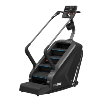
ST-15 Vertex 4 Level Commercial
Stair Climber Stepmill
Product may vary slightly from the item pictured due to model upgrades.
Read all instructions carefully before using this product.
Retain this owner's manual for future reference.
NOTE:
This manual should not be used to guide your purchasing decision. Your product, and the contents inside its carton, may vary
from what is listed in this manual. This manual may also be subject to updates or changes. Updated manuals are available
through our website at
USER MANUAL
www.lifespanfitness.com.au
Advertisement
Table of Contents

Related Manuals for LifeSpan Vertex ST-15


Summary of Contents for LifeSpan Vertex ST-15
- Page 1 ST-15 Vertex 4 Level Commercial Stair Climber Stepmill USER MANUAL Product may vary slightly from the item pictured due to model upgrades. Read all instructions carefully before using this product. Retain this owner’s manual for future reference. NOTE: This manual should not be used to guide your purchasing decision. Your product, and the contents inside its carton, may vary from what is listed in this manual.
-
Page 2: Table Of Contents
TABLE OF CONTENTS Important Safety Instructions ....... . 03 II. Maintenance ..........05 III. -
Page 3: Important Safety Instructions
I. IMPORTANT SAFETY INSTRUCTIONS WARNING: Read all instructions before using this machine. It is important your machine receives regular maintenance to prolong its useful life. Failing to regularly maintain your machine may void your warranty. DANGER: To reduce the risk of electric shock disconnect your stair climber from the electrical outlet prior to cleaning and/or service work. - Page 4 installation position, the "emergency stop" will be displayed on the display and the stair machine cannot be used. Therefore, the surface of the photoelectric switch must be clean and the installation position must be correct. 15. Check the stop button to ensure the brakes wont before use but pressing the start and stop button and checking the emergency stop at the bottom.
-
Page 5: Maintenance
II. MAINTENANCE 1. Cleaning • It is recommended that you clean the equipment before and after each training session. To remove dust from the equipment, use a soft cloth to wet the following cleaning agents and then wipe all exposed surfaces. NOTE: Before using any cleaning agent to clean the fitness equipment, read and follow the manufacturer’s instructions. - Page 6 GROUNDING METHODS This product must be grounded. If it should malfunction or breakdown, grounding provides a path of least resistance for electric current to reduce the risk of electric shock. This product is equipped with a cord having an equipment-grounding conductor and a grounding plug.
-
Page 7: Exploded Diagram
III. EXPLODED DIAGRAM EXPLODED DIAGRAM |... - Page 8 #5 Console support column - 1pc. #4 Rear handrail - 1pc. #41L/R Decorative cover - 1 pair #47 Console - 1pc. #1 Main Frame- 1pc. #44L/R Exterior #45L/R Interior Decorative Decorative cover cover #2L Left Support Column - 1pc. #40 Pedal- 1pc. #58 Decorative cover - 1pc.
-
Page 9: Parts List
IV. PARTS LIST Some items on this list may come pre-installed on your equipment. If you feel like you’re missing anything, please double check your equipment. Name Name Bearing 6004 Main Frame KP005 pedestal bearing 2L/R Support columns 1pr. brake combination 3L/R Handrails 1pr. - Page 10 Name Name Outer snap ring Φ 25 Belt Outer snap ring Φ 8 Anti slip pad C-type snap ring Φ 8 EVA silencing pad Internal serrated washer Φ 10*1.2 Roller Allen bolt M10 * 40 Internal serrated washer Φ 8*1.2 Standard spring washer Φ...
-
Page 11: Assembly Instructions
V. ASSEMBLY INSTRUCTIONS Please follow the below instructions to ensure the machine is assembled correctly. STEP 1 1. Open the package and remove all parts and place the main frame (1) on flat even ground. Ensure you have enough space for setting up. 2. - Page 12 STEP 2 1. Connecting the Console extension wire (104) to the lower wire (105) from the main frame. 2. Assemble the support column (5) on the main frame (1) with screw (68) and washer (95). DO NOT TIGHTEN NOW. 3. Insert the decorative cover (58) and to the support column (5), then buckle it on the main frame (1). | ASSEMBLY INSTRUCTIONS...
- Page 13 STEP 3 1. Pass the switch upper wire 1 (106) through the right decorative cover (41R) to connect with the lower wire 1 (107) on the main frame. 2. Insert the decorative cover (41L / R) on the support column (2L / R), assemble but not tighten the support column (2L / R) on the main frame (1) with screw (69) and washer (95).
- Page 14 STEP 4 1. Connect the pulse extension wire 1 (111 from 3L/3R) to the pulse extension wire 2 (112 from part 4). Connect the key board extension wire 1 (115 from 3L/3R) to the key board extension wire 2 (116 from part 4). 2.
- Page 15 Fig. 1 STEP 5 1. As shown in Figure 1, connect the wires on the console (47) with the corresponding on the rear handrail (4) and the console support column (5) (matched by the same wire number). 2. Tighten the console (47) on the support column (5) with screw (78), then lock the decorative cover (48) on the console (47) with screw (82).
-
Page 16: Operating Instructions
VI. OPERATING INSTRUCTIONS 1. WINDOW DISPLAY 1. "TIME/STEPS" window: Movement time or number of steps is displayed, and will switch every 5 seconds. When the movement time is displayed, the range is from 0:00 to 99:59. Once it reaches the end time 99:59 it will stop running and displays "End"... - Page 17 4. "LEVEL" window Displays the gear value. Ranges from 1 25 gear. 5. "PULSE" window Displays the pulse value of the user. When the user holds the pulse sensors on the handlebars, the system can automatically detect the heartbeat frequency of the user and display it in this window.
- Page 18 3. QUICK START (MANUAL MODE): 1. Turn on the power switch and correctly attach the magnetic safety lock to the safety lock position below the panel. 2. Press the "START" start key, the system enters the 3 seconds countdown and a buzzer will sound. The speed window shows the countdown number, after the 3 seconds countdown, the stair climber starts running at a speed of 1.0 km (0.6 mi) / hour.
- Page 19 7. PROGRAMS: There are 36 built in programs P01 P36 in this system. In non running state, press "Program" to display "P01 P36". Select the desired program, the "TIME" window will flash and display the preset time 10:00. Press "+ / --" or "keypad"...
- Page 20 9. USER CUSTOM PROGRAM: 1. Settings of user custom programs Press the "Custom" key until the user custom program (U01 U03), select and press the "Confirm" key to enter the setting, and then set the first segment. Use the "+/ --" key and key pad to set the values and press the "Confirm" key. Repeat until all segments are set. After setting, the data will be permanently saved until your next reset, the data will not be lost due to power failure.
- Page 21 11. DISPLAY RANGE OF VARIOUS PARAMETERS Set parameters Initial value Set initial value Setting range Display range 0:00 15:00 5:00 99:00 0:00 - 99:59 TIME (minute: second) Block (file) 1 25 1 - 25 5000 100 9990 0 - 9999 Step number (step) Height (m) 10.0...
- Page 22 17. TROUBLESHOOT Test method Error Possible reasons Check Power cord access to the A. No power supply AC, or check the AC socket Place the power switch in the ON B. Power switch not turned on position C. Drive without power supply or Press the overload protector Display not turning on damaged...
-
Page 23: Exercise Guide
VII. EXERCISE GUIDE PLEASE NOTE: Before beginning any exercise program, consult your physician. This is important especially if you are over the age of 45 or individuals with pre-existing health problems. The pulse sensors are not medical devices. Various factors, including the user’s movement, may affect the accuracy of heart rate readings. - Page 24 WORKOUT GUIDELINES HEART RATE MAXIMUM TARGET ZONE COOL DOWN 20 25 30 35 40 45 50 55 60 65 70 This is how your pulse should behave during general fitness exercise. Remember to warm up and cool down for a few minutes. | EXERCISE GUIDE...
-
Page 25: Troubleshooting
VIII. TROUBLESHOOTING There are two types of fault problems: 1. An emergency stop appears on the screen: Emergency stop problem: Check whether the photoelectric switch under the steps is blocked (clean it with a towel), and then check whether the reflective paper is aligned with the sensor probe light (If you do not understand, ask for manufacturer for a video). -
Page 26: Warranty
Any claim against this warranty must be made through your original place of purchase. Proof of purchase is required before a warranty claim may be processed. If you have purchased this product from the Official Lifespan Fitness website, please visit https://lifespanfitness.com.au/warranty-form For support outside of warranty, if you wish to purchase replacement parts or request a repair or service, please visit https://lifespanfitness.com.au/warranty-form and fill in our Repair/Service... -
Page 27: Hand Pulse Technology
X. HAND PULSE TECHNOLOGY This product comes equipped with hand pulse sensors which are used to pick up tiny EKG/ECG signals that run through the body when your heart beats. These electrical EKG/ECG signals are very small and that they must be amplified 1000 times to make the signal useful for the computer to display your pulse. - Page 28 WWW.L IF ESPAN F ITNE S S . COM . A U...
Need help?
Do you have a question about the Vertex ST-15 and is the answer not in the manual?
Questions and answers