Table of Contents
Advertisement
Quick Links
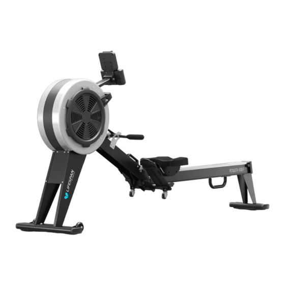
ROWER-801F AIR & MAGNETIC
COMMERICAL ROWING MACHINE
Read all instructions carefully before using this product.
Retain this owner's manual for future reference.
IMPORTANT
All nuts and bolts are to be checked and tightened on a regular basis. This includes pedals and
other moving parts. Failure to do so may cause damage to your threads and void your warranty.
NOTE:
Product may vary slightly from the item pictured due to model upgrades. This manual may be subject to updates or changes.
Up to date manuals are available through our website at www.lifespanfitness.com.au
USER MANUAL
Advertisement
Table of Contents

Related Manuals for LifeSpan ROWER-801F


Summary of Contents for LifeSpan ROWER-801F
- Page 1 ROWER-801F AIR & MAGNETIC COMMERICAL ROWING MACHINE USER MANUAL Read all instructions carefully before using this product. Retain this owner’s manual for future reference. IMPORTANT All nuts and bolts are to be checked and tightened on a regular basis. This includes pedals and other moving parts.
-
Page 2: Table Of Contents
TABLE OF CONTENTS Important Safety Instructions ....... 03 II. Care Instructions ..........04 III. -
Page 3: Important Safety Instructions
I. IMPORTANT SAFETY INSTRUCTIONS WARNING: Read all instructions before using this machine. It is important your machine receives regular maintenance to prolong its useful life. Failing to regularly maintain your machine may void your warranty. Please keep this manual with you at all times. •... -
Page 4: Care Instructions
• Always keep this instruction manual and assembly tools at hand for reference. • The equipment is not suitable for therapeutic use. • The pulse or heart rate sensors are not medical devices. Various factors, including the user’s movement, may affect the accuracy of heart rate readings. The pulse sensors are intended only as exercise aids in determining heart rate trends in general. -
Page 5: Exploded Diagram
III. EXPLODED DIAGRAM EXPLODED DIAGRAM |... - Page 6 | EXPLODED DIAGRAM...
-
Page 7: Parts List
IV. PARTS LIST Description Qty. Description Qty. Computer Footpad Computer Connector Screw ST4.2*19*φ8 Bolt M5*10*φ10 Washer d5*Φ10*1 Bolt M8x90x20xS13 Transportation Wheel Bolt φ16*80.5 Bolt φ7.8*30*M6*15*S5 End Cap 30*15 Bearing608 d8*D22*B7 Main Frame Washer d6*Φ12*1.5 Connector Plate Bolt M6*12*S5 Bolt M5*12*Ф8.5 Adjusting Spindle Bolt M5x16xΦ10 Ball Nut... - Page 8 Description Qty. Description Qty. Bolt M5*12*S5 Scroll Wheel Seat Cover Ribbon Wheel Bolt M8*20*S6 Nut M10*1*H8*S15 Hex Head Bolt Nut M10x1xH5xS17 Seat Slider Sensor Holder BushingΦ12.5*Φ8.2*4.5 Bolt M4*8*φ8 Roller Φ35*Φ8 Sensor Rear Plate Washer d22*1.2 Cover Bolt M8*28*10*S5 Roller Φ36*14 Flywheel Axle Φ12*118 Belt...
-
Page 9: Assembly Instructions
V. ASSEMBLY INSTRUCTIONS NOTE: Some nuts and bolts are attached on the parts, and you will need to remove and re-attach it to the connecting parts. #25 M8*20*S5 2pcs. #30 d8*Ф20*2 2pcs. #A S5 #39 d6*Ф12*1.5 2pcs. #48 d8 2pcs. #56 M6*20*S5 2pcs. - Page 10 #25 M8*20*S5 4pcs. #48 d8 4pcs. #30 d8*Ф20*2 4pcs. #A S5 STEP 2 CAUTION: Be careful of fingers as the seat will move. a. Push adjustable spindle (41), then rotate rail connector (51) to the position as shown in the instruction image.
- Page 11 #25 M8*20*S5 2pcs. #30 d8*Ф20*2 2pcs. #112 ST4.8*13*Ф8 #B S13-14-15 STEP 3 a. Secure bolt (112) on the rail (55) using wrench (B), to avoid alum plate (63) runs off the rail (55). b. Take out the bolts (25) and washers (30) from front stabilizer (31) using spanner (A). Attach front stabilizer (31) to main frame (7) using bolts (25) and washers (30).
- Page 12 #25 M8*20*S5 2pcs. #48 d8 4pcs. #30 d8*Ф20*2 4pcs. #50 M8*30*S5 2pcs. B S13-14-15 30 48 25 48 STEP 4 a. Secure transportation wheels (49) in the pedal plate (47). b. Take out bolts (25), bolts (50), spring washers (48) and washers (30) from main frame (7) using spanner (7).
- Page 13 #4 M8*90*20*S13 1pc. #27 M8*H7.5*S13 1pc. #111 M4*10*Ф8 4pcs. #B S13-14-15 1pc STEP 5 a. Place the Computer wire (1a) through the hole of iPad holder (110) then connect computer wire (1a) and trunk wire 1 (85), as shown in image E. b.
- Page 14 STEP 6 Insert the adapter line (28) to power hole on the back of main frame (7), then plug the adapter into an outlet. IMPORTANT: Turn off the equipment when not in use. | ASSEMBLY INSTRUCTIONS...
- Page 15 Display & Holder Adjustment The rotation angle of computer post The width of iPad holder can be can be adjusted to obtain the best adjusted to different size tablet. view of the console LCD screen. The pedal strap (43) and pedal (46) are adjustable and can be personalized to fit the user’s foot size.
- Page 16 The rotation angle of air adjustable handlebar (11) can be adjusted to control air intake. Upward adjustment can increase the wind inflow to increase the resistance. Downward adjustment can reduce the wind flow to decrease the resistance. | ASSEMBLY INSTRUCTIONS...
-
Page 17: Transport And Folding Instructions
VI. TRANSPORTING AND FOLDING INSTRUCTIONS The equipment has transportation wheels at the front and middle section. To move the equipment, you will need to fold it first. How to Fold: STEP 1 First rotate the display so it is moved out of the way. STEP 2 Pull the Adjusting spindle (41) up as pictured in image. - Page 18 STEP 3 Move the seat to the front of the rower as the seat will roll down when folding. STEP 4 Pull the rail up from the back up into a vertical position. You will hear a click when it is locked in place. | TRANSPORT AND FOLDING INSTRUCTIONS...
- Page 19 STEP 5 You can now use the handle under the rail to move the rower. How to Un-Fold: STEP 1 Hold onto the rail part and push the Adjusting spindle (41) down as pictured in image. You can then lower the rail down. TRANSPORT AND FOLDING INSTRUCTIONS |...
- Page 20 STEP 2 Then using the handle on Main frame (7), pull the rail up until you hear a click. Be careful of your fingers as the seat may roll back. | TRANSPORT AND FOLDING INSTRUCTIONS...
-
Page 21: Operation Guide
VII. OPERATION GUIDE A: 1 Manual Program B: 10 Preset Program Profile (PROGRAM: P1-P10) OPERATION GUIDE |... - Page 22 P1: ROLLING P2: VALLEY P3: FATBURN P4: RAMP P5: MOUNTAIN P6: INTERVAL P7: CARDIO P8: ENDURANCE P9: SLOPE P10: RALLY C: 1 Watt Control Program (WATT PRO: P16) D: 4 Heart Rate Control Program: (PULSE PRO: P17-P20) 55% H.R, 75% H.R, 95% H.R and TARGET H.R | OPERATION GUIDE...
- Page 23 E: 5 User Setting Programs: CUSTOM1 to CUSTOM5 (P11 ~ P15) 1. Record the user’s data of 5 User Setting Programs. 2. Display Count (RPM), TIME and WATT., CAL and DIST, at the same time. 3. The computer will turn off automatically if there is no operation, count signal and pulse signal over 4 minutes.
- Page 24 BUTTONS 1. ENTER • In "stop" mode, press ENTER button to enter into program selection and setting value which flash in related window. A: When you choose the program, press Enter to confirm the one you like. B: When in setting, press ENTER to confirm the value that you would like to preset. •...
- Page 25 • Watt Control Program (WATT PRO:P16) A. Press UP, DOWN to select the watt control program. B. Press ENTER to confirm the selected watt control program and enter into time setting window. C. The time will flash, and then press UP, DOWN button to set up the desired time. Press ENTER to confirm the value.
- Page 26 HEART RATE CONTROL PROGRAM: TARGET HEART RATE (PULSE PRO: P20) The user can set any target heart rate to do the exercise. A. Press UP, DOWN button to select TARGET HEART RATE program. B. Press ENTER to confirm your choice and enter time setting window. C.
- Page 27 SPECIFICATIONS COUNT: Showing your current speed. Range: 0.0~999 count. RPM: Showing the current rotate per minute. Range: 0~999. TIME: The accumulative exercise time, range: 0:00~99M59S. The preset time range is 5:00~99M00S. The computer will start to count down from preset time to 0:00 with average time for each resistance level.
-
Page 28: Exercise Guide
VIII. EXERCISE GUIDE PLEASE NOTE: Before beginning any exercise program, consult your physician. This is important especially if you are over the age of 45 or individuals with pre-existing health problems. The pulse sensors are not medical devices. Various factors, including the user’s movement, may affect the accuracy of heart rate readings. - Page 29 COOL DOWN Finish each workout with a light jog or walk for at least 1 minute. Then complete 5 to 10 minutes of stretching to cool down. This will increase the flexibility of your muscles and will help prevent post- exercise problems.
-
Page 30: Warranty
Any claim against this warranty must be made through your original place of purchase. Proof of purchase is required before a warranty claim may be processed. If you have purchased this product from the Official Lifespan Fitness website, please visit https://lifespanfitness.com.au/warranty-form For support outside of warranty, if you wish to purchase replacement parts or request a repair or service, please visit https://lifespanfitness.com.au/warranty-form and fill in our Repair/Service... - Page 32 WWW.LIFESPA NF ITN ES S.COM.AU...
Need help?
Do you have a question about the ROWER-801F and is the answer not in the manual?
Questions and answers