Table of Contents
Advertisement
Quick Links
Advertisement
Table of Contents

Subscribe to Our Youtube Channel
Related Manuals for Bosch VCU MS 50.4P


Summary of Contents for Bosch VCU MS 50.4P
- Page 1 Vehicle Control Unit VCU MS 50.4P Manual Version 1.0 11/03/2021...
-
Page 2: Table Of Contents
13.1 Setting up an online measurement................................13.2 Online calibration of measurement channels............................13.3 Online calibration of multipoint adjustment channels .......................... 14 Recording..................................14.1 Features ............................................ 14.2 Configuration of Recordings.................................... 14.3 Event Logging ........................................14.4 USB Recording........................................14.5 High speed logging ......................................ii / 136 Vehicle_Control_Unit_VCU_MS_50.4P_Manual Bosch Motorsport... - Page 3 20 Fuel Consumption Calculation ............................20.1 Setting up fuel consumption calculation and tank management ..................... 20.2 Fuel consumption diagnosis/counter reset..............................21 RaceCon Shortcuts................................22 Legal ....................................22.1 EC/EU Declaration of Conformity................................... 22.2 REACH Statement......................................... 23 Disposal.................................... Bosch Motorsport Vehicle_Control_Unit_VCU_MS_50.4P_Manual iii / 136...
-
Page 4: Preparation
To avoid unwanted interference with the environment (people, animals, electronic devices) or unwanted harm to the environment, it is mandatory that the user of the VCU MS 50.4P carries out an appropriate analysis to determine the electromagnetic interaction the VCU MS 50.4P may have with its individual installation environment. -
Page 5: Warnings And Safety Instructions
Warning of death or serious injury, which can occur if this is not observed. Caution CAUTION Nature and source of danger Consequences Warning of slight bodily injury in case of Disregard. Notice NOTICE Nature and source of danger Consequences Warning of damage to equipment in case of ignoring. Bosch Motorsport Vehicle_Control_Unit_VCU_MS_50.4P_Manual 5 / 136... -
Page 6: Onboard Network Concept
Be careful to observe current limits of wires and connector pins! IGN- Switch UBAT Star connection switched pos. terminal (term30) positive terminal Electric Loads Main KL15 Switch KL30 Bosch Motorsport Device diagnosis connector µC LS_SWITCH1…4 KL31 UBATT_FUSE GND_Starpoint SENSPWR10 Star connection Chassis dig. sensors (e.g. wheelspeed) -
Page 7: Technical Data
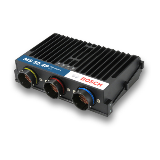
Technical Data | 4 4 Technical Data The VCU MS 50.4P (Performance) is a highly powerful processing / logging unit for race applications. Based on our broad base of platform function, we support you with customized VCU func- tions for a tailor-made solution. - Page 8 Data Analysis tool WinDarab 7 System Configuration tool RaceCon Logger configuration, calibration and on- line measurement Upgrade Customer Code Area CCA Provides the option to run customer developed software code on Bosch ECU Upgrade I/O Package Communication 4 CAN Inputs 8 / 136...
- Page 9 SERCOS3 slave. USB Accessories Rugged USB flash drive Mating connector for USB flash drive on car loom side Adapter cable to PC USB-port Connectors Connector LIFE (red) AS018-35PN Mating connector AS618-35SN (not in- cluded) Bosch Motorsport Vehicle_Control_Unit_VCU_MS_50.4P_Manual 9 / 136...
- Page 10 4 | Technical Data Connector SENS-A (yellow) AS018-35PA Mating connector AS618-35SA (not in- cluded) Connector SENS-B (blue) AS018-35PB Mating connector AS618-35SB (not in- cluded) 10 / 136 Vehicle_Control_Unit_VCU_MS_50.4P_Manual Bosch Motorsport...
-
Page 11: Pinlayout
LIFE 32 B_D_SERCOS2TXN LIFE 33 B_D_SERCOS2TXP LIFE 34 B_D_ETH3RXN LIFE 35 B_D_ETH3RXP LIFE 36 B_D_ETH3TXP LIFE 37 I_DIGIN03_HALL_DF11 0 to 5 V LIFE 38 BI_CAN6_H 0 to 5 V LIFE 39 BI_CAN6_L 0 to 5 V Bosch Motorsport Vehicle_Control_Unit_VCU_MS_50.4P_Manual 11 / 136... - Page 12 GND, 2 A fused SENS-A 08 O_HSOUT3 VBAT / 8 A SENS-A 09 O_HSOUT3 VBAT / 8 A SENS-A 10 O_LSOUT5 VBAT / 2 A SENS-A 11 G_SENSGND08 GND, 2 A fused SENS-A 12 G_SENSGND07 GND, 2 A fused 12 / 136 Vehicle_Control_Unit_VCU_MS_50.4P_Manual Bosch Motorsport...
- Page 13 0 to 5 V SENS-A 50 I_ANA24_5V 0 to 5 V SENS-A 51 I_LVDT4_SEC1P -5 to 5 V SENS-A 52 O_LVDT4_PRI1 -5 to 5 V SENS-A 53 I_LVDT3_SEC_M -5 to 5 V SENS-A 54 G_SCR_LVDT3 GND, 2 A fused Bosch Motorsport Vehicle_Control_Unit_VCU_MS_50.4P_Manual 13 / 136...
- Page 14 -5 to 5 V SENS-B 23 O_LVDT1_PRI2 -5 to 5 V SENS-B 24 I_LVDT1_SEC2N -5 to 5 V SENS-B 25 O_HSOUT1 VBAT / 8 A SENS-B 26 O_HSOUT1 VBAT / 8 A SENS-B 27 G_SENSGND11 GND, 2 A fused 14 / 136 Vehicle_Control_Unit_VCU_MS_50.4P_Manual Bosch Motorsport...
- Page 15 0 to 5 V SENS-B 62 I_ANA04_5V 0 to 5 V SENS-B 63 I_ANA_HSL1 0 to 5 V SENS-B 64 I_ANA_HSL6 0 to 5 V SENS-B 65 I_ANA03_5V 0 to 5 V SENS-B 66 I_ANA_HSL3 0 to 5 V Bosch Motorsport Vehicle_Control_Unit_VCU_MS_50.4P_Manual 15 / 136...
-
Page 16: Communication Channels
The VCU MS 50.4P has two CAN buses configurable as input and output. Different baud rates are selectable. Please note that the VCU MS 50.4P does not contain any CAN termin- ation resistors. Thus, the CAN termination resistors need to be integrated into the wiring loom. -
Page 17: Mechanical Drawing
Mechanical Drawing | 7 7 Mechanical Drawing 86.6 YAW RATE SENSOR Drehratensensor 86.6 Bosch Motorsport Vehicle_Control_Unit_VCU_MS_50.4P_Manual 17 / 136... -
Page 18: Starting Up
8 | Starting Up 8 Starting Up Install the software required for the VCU MS 50.4P operation. It is developed for Windows system software. Following software versions are used in this manual: – VCU MS 50.4P setup, configuration and calibration: RaceCon –... - Page 19 – the Logger program archive and the ECU program archive. For the Logger program archive, go to the Toolbox and select the VCU MS 50.4P. Drag it into the Main Area. A pop up window appears, to specify the VCU MS 50.4P Logger program archive.
- Page 20 In the next step, the ECU needs to be specified. A pop up window appears, to specify the ECU program archive. Download the firmware for the VCU MS 50.4P from www.bosch-motorsport.com. An information shows if the archive is valid or not.
- Page 21 Select ‘Race track’ or ‘Testbench’ mode according to your application. Click ‘Finish’. The VCU MS 50.4P is inserted into the project and RaceCon tries to connect to the device. RaceCon detects configuration differences between the VCU MS 50.4P and the Race- Con project and asks for permission for data download.
- Page 22 The download starts and the VCU MS 50.4P carries out a reset. After the reset, RaceCon reconnects to the VCU MS 50.4P. Local configuration on both the PC and VCU MS 50.4P match (indicated by green background and dot). The VCU MS 50.4P is now connected to RaceCon.
-
Page 23: Feature Activation
– The feature activation status is stored permanently in the device and requires activat- ing once only. – As the activation key is device specific, a key delivered with one VCU MS 50.4P does not work on any other VCU MS 50.4P. - Page 24 Enter the activation key you received for this feature on this device and click ‘OK’ when done. The feature’s status changes to ‘unlocked’. Perform these steps to activate other features you purchased. Switch the car’s ignition off and on again to cycle the power of VCU MS 50.4P. 24 / 136 Vehicle_Control_Unit_VCU_MS_50.4P_Manual...
-
Page 25: First Recording (Quick Start)
Drag + Drop Click on the ‘Download’ button in the upper left corner. The configuration download starts and the VCU MS 50.4P carries out a reset. Now you can find the ‘ub’ measurement channel in the ‘Data Area’. Bosch Motorsport Vehicle_Control_Unit_VCU_MS_50.4P_Manual... - Page 26 8 | Starting Up As we did not define global start conditions, recording starts immediately. Start the WinDarab software. Disconnect the VCU MS 50.4P network cable. Click on the ‘Read Data from Logging Device’ icon. Choose your logger and click ‘OK’ when done.
- Page 27 10. Click ‘Apply changes’ when done. Choose your Device / IP from dropdown list 11. Connect the VCU MS 50.4P network cable. 12. Click on the ‘Current Import’ tab. 13. Click on ‘Import’ in the lower right corner. If the ‘Import all on connect’ box is checked, the data transmission from the VCU MS 50.4P starts automatically.
-
Page 28: Set Date And Time
8 | Starting Up 8.4 Set date and time The VCU MS 50.4P is equipped with a real time clock which is supplied by an internal ac- cumulator. Once this accumulator is charged correctly by 12 V supply of the display, ‘Date &... - Page 29 A ‘Set Date & Time’ menu opens Set the current local date and time as coordinated universal time. At ‘Set a specific date & time’ click and type on the value you want to change, or choose from the dropdown menu. Bosch Motorsport Vehicle_Control_Unit_VCU_MS_50.4P_Manual 29 / 136...
-
Page 30: Project Configuration
Enter the formula. d) Select the logical operator. e) Choose a measurement channel. f) Define a value that can be used as a constant in the formula. g) Choose a function. h) Describes the function selected above. 30 / 136 Vehicle_Control_Unit_VCU_MS_50.4P_Manual Bosch Motorsport... -
Page 31: Conditional Functions
Project Configuration | 9 Click ‘Finish’ when done. The math channel is displayed in the VCU MS 50.4P math chan- nel window. 9.2 Conditional Functions – Arithmetic and logical operations on one or more measurement channel(s) – If-Else structure with reset –... - Page 32 An example of a condition to set up the maximum front brake pressure is given on the next page. The conditional function is displayed in the VCU MS 50.4P math channel window. Example: Setting up a condition for maximum front brake pressure Brake pressure ‘front p_br_front’...
-
Page 33: Conditional Channels
– Result can be used as input source for alarm display elements and further calculations in the whole RaceCon project. Creating a new Conditional Channel Follow the steps shown in the screenshot. The “Create/edit condition” window appears. Bosch Motorsport Vehicle_Control_Unit_VCU_MS_50.4P_Manual 33 / 136... - Page 34 – Pulse: Result is a short one-time pulse, if the condition is fulfilled. – Toggling output: Result is a pulse that lasts until the next condition is fulfilled. – Click ‘Ok’ when done. The conditional channel is displayed in the VCU MS 50.4P con- dition channel window.
-
Page 35: Condition Combination
– Combination of several (up to 16) conditional channels for more complex calculations – Logical results – All conditions can be used globally in the whole VCU MS 50.4P project. Creating a new Condition Combination Follow the steps shown in the screenshot. - Page 36 – Pulsing: Result is a short one-time pulse, if the condition is fulfilled. – Toggling output: Result is a pulse that lasts until the next condition is fulfilled. Click ‘Finish’ when done. The conditional combination is displayed in the VCU MS 50.4P condition channel window.
-
Page 37: Display Switch Module
The page can be configured to wrap around. In this case, no page down condition is needed. The resulting outputs are the display switch value and the input conditions. Measurement label Function name page or brightness value name_dn input condition for decrement name_up input condition for increment Example: Bosch Motorsport Vehicle_Control_Unit_VCU_MS_50.4P_Manual 37 / 136... -
Page 38: Timer Module
There are 2 x 10 GPS trigger points available, 10 in the parameter and 10 in the macro-based mode. If the car passes one of the trigger points, an output signal is set to 1 shortly. Each trigger requires a defined latitude, longitude and detection range. 38 / 136 Vehicle_Control_Unit_VCU_MS_50.4P_Manual Bosch Motorsport... - Page 39 The GPS trigger points can also be used for segment triggering. If used as segment trig- gers and i.e. 3 trigger points are selected, the laptrigger module will use the first 3 trigger points on the list. Bosch Motorsport Vehicle_Control_Unit_VCU_MS_50.4P_Manual 39 / 136...
-
Page 40: Cpu Load Limits
– Logger configuration (total logging rate [kB/s], conditional measurement rates) To help respecting the limit of 85 % CPU load, the VCU MS 50.4P creates an error memory entry. To trigger this error entry, the CPU load must exceed the limit for 5 minutes without interruption. -
Page 41: Can Configuration
– Baudrate 125 kbaud to 1 Mbaud – 11 Bit or 29 Bit identifiers – Input configuration: Read messages from CAN bus and convert to VCU MS 50.4P measurement/display variables. CAN bus supports row counter configuration. – Output configuration: Write RaceCon measurement variables to CAN messages; out- put frequency and row counter are configurable, CAN gateway functionality (transfer from one bus to another). -
Page 42: Can Input
10.2.2 Create new CAN Input channel Double-click on any CAN bus item, to open the "CAN messages overview". Select ‘Add CAN-IN’ and choose the desired CAN bus for the new input channel. A CAN channel configuration window opens. 42 / 136 Vehicle_Control_Unit_VCU_MS_50.4P_Manual Bosch Motorsport... - Page 43 CAN Configuration | 10 Insert the name and description of the channel. Click ‘OK’ when done. The channel is listed in the Data window. Bosch Motorsport Vehicle_Control_Unit_VCU_MS_50.4P_Manual 43 / 136...
- Page 44 Enter CAN message ID. If extended IDs (29 bit) are used, check the box. b) If replacement values are used, specify time-out period and raw value. c) If a multiplexer (row counter) is used, check the box. 44 / 136 Vehicle_Control_Unit_VCU_MS_50.4P_Manual Bosch Motorsport...
- Page 45 Enter offset for conversion to physical value. c) Select type of physical value. d) Select unit of physical value. e) Enter minimum physical limit of the channel. (for manual setup) f) Enter maximum physical limit of the channel. (for manual setup) Bosch Motorsport Vehicle_Control_Unit_VCU_MS_50.4P_Manual 45 / 136...
- Page 46 For an online view of the value measured by the VCU MS 50.4P, insert the channel in an online measurement sheet which is described in the chapter Setting up an online meas- urement [} 73].
- Page 47 10.2.5 Import a CAN database (DBC) file Right-click on CAN Input of desired bus (CAN1 or CAN2). Select ‘Import DBC file’ from menu. A file browser opens. Select DBC file to import and click ‘OK’ when done. A channel import window opens. Bosch Motorsport Vehicle_Control_Unit_VCU_MS_50.4P_Manual 47 / 136...
-
Page 48: Can Output
Export RaceCon CAN output configuration to file Import RaceCon CAN out configuration from file Display CAN bus properties (Baudrate) 10.3.2 Create a new CAN output message channel – Double-click on any CAN bus item to open the "CAN messages overview". 48 / 136 Vehicle_Control_Unit_VCU_MS_50.4P_Manual Bosch Motorsport... - Page 49 – Enter name of message, description, CAN-Id and Grid (output interval). Optionally, specify a multiplexer. Definition of CAN message Content of message – Click on ‘Add channel’ or ‘Add constant’, this opens the ‘Add new CAN out channel’ window. Bosch Motorsport Vehicle_Control_Unit_VCU_MS_50.4P_Manual 49 / 136...
-
Page 50: Multiplexer
– Re-use (multiplex) of message identifiers by splitting it into several rows. – Every row is assigned to a unique value of the multiplexer. – One byte of message contains row counter. 50 / 136 Vehicle_Control_Unit_VCU_MS_50.4P_Manual Bosch Motorsport... - Page 51 Select a channel and configure it. To assign it to the row selected before, check the box ‘Multiplexed’. To move the channel message, change the “Start” value or click and hold the green field in the “Add new CAN out message” window. Click ‘OK’ when done. Bosch Motorsport Vehicle_Control_Unit_VCU_MS_50.4P_Manual 51 / 136...
- Page 52 10 | CAN Configuration 10. The channel message is assigned to the selected fields. 11. Click ‘OK’ when done. 52 / 136 Vehicle_Control_Unit_VCU_MS_50.4P_Manual Bosch Motorsport...
-
Page 53: Analog And Frequency Inputs
Filtered physical value Filtered channels are routed through digital low pass filters: – VCU MS 50.4P uses A/D converter oversampling and digital filtering to recording rate – Digital filters eliminate ‘out-of-band’ noise – Cut-off frequency automatically adjusted to recording rate –... -
Page 54: Configuring Inputs
'Bosch Sensor Wizard' Click on ‘Measurement Sources’ in the Toolbox. To expand the list of ‘I/O Channels’, click on ‘+’ in the VCU MS 50.4P Project Tree. Drag the “Bosch Sensor Wizard” from the Toolbox and drop it on the desired analog input channel in the VCU MS 50.4P Project Tree. - Page 55 Click ‘Finish’ when done. The “Create channel” window opens. Enter the channel name and description. Click ‘Ok’ when done. The channel is inserted into the VCU MS 50.4P Project Tree. Channel is linked to ANA03 Calculation of Input pin Pull-up...
- Page 56 To activate the internal pullup-resistor, check the box. The internal pullup-resistor is used to get a 5 V signal at the analog channel of the VCU MS 50.4P. It allows you to use a push-button. The fixed value of the internal pullup-resistor is 3,010 Ohm. If us- ing an additional external pullup-resistor, set up the overall resistance.
- Page 57 Click ‘Finish’ when done. Enter a channel name and a description. Click ‘OK’ when done. The channel is inserted into the VCU MS 50.4P Project Tree. Name and Channel is linked Description to ANA04 editable...
- Page 58 Thermistor Click ‘Measurement Sources’ in the Toolbox. To expand the list of ‘I/O Channels’, click on ‘+’ in the VCU MS 50.4P Project Tree. Drag the “Characteristic Curve” analogue signal source from the Toolbox and drop it on the desired analogue input channel in the VCU MS 50.4P Project Tree.
- Page 59 To activate the internal pull up-resistor, check the box. The VCU MS 50.4P pull up-res- istor is used to get a 5 V signal at the analogue channel of the VCU MS 50.4P. It al- lows you, to use a push-button. The fixed value of the internal pull up-resistor is 3,010 Ohm.
- Page 60 Click ‘Finish’ when done. Enter channel name and description. Click ‘OK’ when done. The channel is inserted into the VCU MS 50.4P Project Tree. Channel is linked to ANA05 Characteristic Adjustment curve for sensor...
- Page 61 – Curve definition by online adjustment at vehicle Click on ‘Measurement Sources’ in the Toolbox. Expand the list of ‘I/O Channels’ by clicking on ‘+’ in the VCU MS 50.4P Project Tree. Drag the ‘Multipoint Adjustment’ analog signal source from the Toolbox and drop it on the desired analog input channel in VCU MS 50.4P Project Tree.
- Page 62 To activate the internal pullup-resistor, check the box. The internal pullup-resistor is used to get a 5 V signal at the analog channel of the VCU MS 50.4P. It allows you to use a push-button. The fixed value of the internal pullup-resistor is 3.01 kOhm. If us- ing an additional external pullup-resistor, set up the overall resistance.
- Page 63 Click ‘Finish’ when done. Enter channel name and description. Click ‘OK’ when done. The channel is inserted into the VCU MS 50.4P Project Tree. Channel is linked to ANA06 Characteristic Adjustment curve for sensor...
- Page 64 11 | Analog and Frequency Inputs 11.2.5 Digital filter details VCU MS 50.4P uses A/D converter oversampling and digital filtering to recording rate. Digital filters eliminate ‘out-of-band’ noise Cut-off frequency automatically adjusted to recording rate Example: – 100 Hz recording rate (10 ms) –...
- Page 65 Click on ‘Measurement Sources’ in the Toolbox. To expand the list of ‘I/O Channels’, click on the ‘+’ in the VCU MS 50.4P Project Tree. Drag the ‘Velocity’ digital signal source from the Toolbox and drop it on the desired ‘REV’...
- Page 66 Enter name to automatically create a new measurement sheet Click ‘Finish’ when done. Enter the channel name and description. Click ‘OK’ when done. The channel is inserted into the VCU MS 50.4P Project Tree. Channel is linked to REV01 Input pin Number of...
-
Page 67: Configuring Computed Sources
Example: Sensitivity/offset calculation on input channel Click ‘Measurement Sources’ in the Toolbox. Drag the ‘Sensitivity/Offset’ computed source from the Toolbox and drop it on ‘Com- puted Channels’ in the VCU MS 50.4P Project Tree. Drag + Drop A ‘Computed Sensitivity/Offset Wizard’ opens. -
Page 68: Hysteresis
Click ‘Finish’ when done. Enter channel name and description. Click ‘OK’ when done. The channel is inserted into the VCU MS 50.4P Project Tree. Note Working with automatically created measurement sheets is explained in chapter ‘Setting up an online measurement [} 73]’. - Page 69 CAN system Enter name to automatically create a new measurement sheet Click ‘Finish’ when done. Enter channel name and description. Click ‘OK’ when done. The channel is inserted into the VCU MS 50.4P Project Tree. Bosch Motorsport Vehicle_Control_Unit_VCU_MS_50.4P_Manual 69 / 136...
- Page 70 Click on tab ‘System Overview’. Click on ‘Measurement Sources’ in the Toolbox. Drag the ‘Speed’ computed source from the Toolbox and drop it on the project name in the VCU MS 50.4P Project Tree. Do not drop it on ‘VCU MS 50.4P’! 70 / 136 Vehicle_Control_Unit_VCU_MS_50.4P_Manual...
- Page 71 Choose driven axle Choose individual wheel speed channels Set limit for speed difference for calculation Click ‘Finish’ when done. The speed calculation is inserted into the VCU MS 50.4P Project Tree. Speed calculation in DDU Project Tree Measurement channels calculated speed...
-
Page 72: Power Stages
12 | Power Stages 12 Power Stages Power stage details The VCU MS 50.4P uses integrated power stages with built-in diagnosis. For the high side switches, overload-behaviour (mode “bulb” or “DC motor”, restarts etc.) is determined in- side the IC itself. -
Page 73: Online Measurement And Calibration
VCU MS 50.4P configuration – System configuration (channel + display configuration, CAN I/O, etc.) is stored in the VCU MS 50.4P – Use RaceCon to create and download configuration from the PC to VCU MS 50.4P Communication interface: Ethernet – Communication protocol: XCP Online Measurement and Calibration –... - Page 74 Drag a measurement element from the Toolbox and drop it on the measurement sheet. Drag + Drop Select the desired measurement channel from the ‘Data’ area and drop it on the measurement element. If the VCU MS 50.4P shows the green status, the value is displayed. 74 / 136 Vehicle_Control_Unit_VCU_MS_50.4P_Manual Bosch Motorsport...
- Page 75 Numeric indicator Oscilloscope (Chart) 13.1.1 Automatic creation of measurement sheets RaceCon can create measurement sheets automatically. You can create and use measurement sheets with the VCU MS 50.4P as well as with all other devices connected to RaceCon. Bosch Motorsport Vehicle_Control_Unit_VCU_MS_50.4P_Manual...
- Page 76 Drag + Drop During the configuration of a measurement channel, select a measurement sheet from the list box or enter a name for a new measurement sheet. Select existing sheet from list or enter name of new sheet 76 / 136 Vehicle_Control_Unit_VCU_MS_50.4P_Manual Bosch Motorsport...
- Page 77 The automatically created sheet is inserted in the Project Tree under ‘Measurement Container’ and ‘Device Channels’. If the VCU MS 50.4P is connected to RaceCon and the status is green, live values of the channels are shown. 13.1.2 Using the measurement sheets When RaceCon is online, press the ‘F11’...
-
Page 78: Online Calibration Of Measurement Channels
– Analog sensors drift with age, temperature, etc. – Manual calibration is necessary – Solution: online offset calibration – Example: acceleration sensor 13.2.1 Enable online offset calibration for measurement channel During creation of the measurement channel 78 / 136 Vehicle_Control_Unit_VCU_MS_50.4P_Manual Bosch Motorsport... - Page 79 13.2.2 Performing the online offset calibration VCU MS 50.4P has to be connected to RaceCon to calibrate the sensor’s offset. Apply the desired physical condition to the sensor (e.g. 1 G to an acceleration sensor). Open the measurement channel’s online page by double-clicking on the measure- ment channel name in the Data Area.
-
Page 80: Online Calibration Of Multipoint Adjustment Channels
Create a multipoint adjustment measurement channel. To create a multipoint channel, see chapter ‘Configuring a multipoint adjustment [} 61]’. Download the configuration on the VCU MS 50.4P. To connect the VCU MS 50.4P to RaceCon, see chapter ‘Setting up a new RaceCon Project’. - Page 81 Online Measurement and Calibration | 13 Press the ‘Calibrate’ button of the desired calibration point. Repeat for all curve points. 10. Click ‘Close’ when done. The calibration curve is displayed in the online view. Adjustment points vs. offset adjustment Bosch Motorsport Vehicle_Control_Unit_VCU_MS_50.4P_Manual 81 / 136...
-
Page 82: Recording
– Up to 16 measurement conditions (fast-slow-switches) 14.2 Configuration of Recordings Expand the ‘Logger’ list by clicking on ‘+’ in the VCU MS 50.4P Project Tree. Double-click on ‘Logging’ in the VCU MS 50.4P Project Tree. The recording configuration is displayed in the Main Area. - Page 83 To add a measurement channel to a recording, select the wanted channel, drag and drop it onto the measurement group. Recording properties Drag measurement channels into group To edit channel settings, mark the channel(s) and click ‘Edit Recording Channel(s)’. Bosch Motorsport Vehicle_Control_Unit_VCU_MS_50.4P_Manual 83 / 136...
- Page 84 The ‘Logger’ window opens. Click on the ‘Add’ button. A new group will be added and can be renamed ‘Gearbox’, ‘Aero’, ‘Engine’, etc.. To rename a group, click on the ‘Rename’ button next to the ‘Add’ button. 84 / 136 Vehicle_Control_Unit_VCU_MS_50.4P_Manual Bosch Motorsport...
- Page 85 The overview helps to detect bandwidth bottlenecks of channels. Bandwidth bottlenecks can be solved by changing the logging rate setting for each channel. The data rate of the whole system is often less than the data rate of the VCU MS 50.4P and limits the overall transmission speed.
-
Page 86: Event Logging
0, a red highlighted channel means 1. – Measurement correctly initialized, but recording threshold(s) not reached: 254 – Measurement correctly initialized, VCU MS 50.4P is recording data: 255 – Values less than 254 indicate an error state 14.3 Event Logging... -
Page 87: Usb Recording
USB_DATA, enter the license key as described in the chapter ‘Feature activation’. For USB recording, Software Upgrade FULL_LOG_1 should also be enabled. Wiring harness Value USB_Device_Power Power (red) USB_Device_DP D+ (green) USB_Device_DN D- (white) USB_Device_Gnd GND (black) For further information, see the pinlayout of the device. Bosch Motorsport Vehicle_Control_Unit_VCU_MS_50.4P_Manual 87 / 136... - Page 88 Power on the system and connect with RaceCon to the vehicle. Download the configuration to the VCU MS 50.4P. Record measurement data. If an USB device is present, the VCU MS 50.4P stores the data in parallel on the internal memory and the USB device.
- Page 89 11. Click on ‘Settings’ tab and select the option ‘Flash Card/USB Stick’. 12. Activate ‘Apply changes’. Insert the USB device into the PC. Data transmission from device starts automatically. Measurement files are stored automatically in the base folder. Bosch Motorsport Vehicle_Control_Unit_VCU_MS_50.4P_Manual 89 / 136...
- Page 90 18. Drag the desired measurement channel from the Channel list and drop it into the measurement data window. The measurement channel‘s graph is displayed For more detailed descriptions and instructions, refer to the WinDarab V7 manual. 90 / 136 Vehicle_Control_Unit_VCU_MS_50.4P_Manual Bosch Motorsport...
-
Page 91: High Speed Logging
USB device. If the USB device is plugged in after recording has started, only the current data is saved. Data recorded on the VCU MS 50.4P before the USB device is plugged in will not be saved. - Page 92 To include these channels into the logging, display the list of logged channels and drag and drop into the list the hs_ana_xx channel you want to be logged. Attention: This will only work if “flat view” is deactivated. 92 / 136 Vehicle_Control_Unit_VCU_MS_50.4P_Manual Bosch Motorsport...
- Page 93 Recording | 14 After double clicking the logging list entry you just created, set the desired logging rate. You will note that for hs_ana_xx channels, logging frequencies of more than 1 kHz are available. Bosch Motorsport Vehicle_Control_Unit_VCU_MS_50.4P_Manual 93 / 136...
-
Page 94: Error Memory
DDU 8. Please consider this and replace the product name ‘DDU 8’ in this case with the name of your product. 15.1 Error memory representation in RaceCon Bosch Motorsport devices feature an error memory. Information on errors can be visual- ized via RaceCon (online measurement) or can be transmitted via telemetry. 15.1.1 Accessing the memory The error memory can be accessed as shown in the illustration: 94 / 136... - Page 95 The error memory is not cleared by a configuration download and is not cleared by a power cycle. 15.1.2 Clearing the error memory There are two ways of clearing the error memory, both are shown in the following illustra- tion: Bosch Motorsport Vehicle_Control_Unit_VCU_MS_50.4P_Manual 95 / 136...
-
Page 96: Information On Errors Available From The Error Memory
1: at least one inactive error present in memory, no active errors 2: at least one active error present in memory If displayed in a measurement sheet, this property’s value (0, 1 or 2) is translated into a verbal description: 96 / 136 Vehicle_Control_Unit_VCU_MS_50.4P_Manual Bosch Motorsport... - Page 97 0 (no error present in memory): No orange border MIL off (black) No entries 1 (at least one inactive error present in memory, no active errors): Constantly orange border MIL constantly orange Info cycling through errors, present in error memory Bosch Motorsport Vehicle_Control_Unit_VCU_MS_50.4P_Manual 97 / 136...
- Page 98 All failure modes are continuously diagnosed; any error detected will be written to the error memory. Once an error is detected, it is qualified as “active”. – 1 (TRUE) Error was detected in most recent diagnose run (active) 98 / 136 Vehicle_Control_Unit_VCU_MS_50.4P_Manual Bosch Motorsport...
- Page 99 (while more than one error is active) and watch the values change periodically: The verbal representation of the numerical codes of these labels can be visualized in the properties window of the measurement page: Bosch Motorsport Vehicle_Control_Unit_VCU_MS_50.4P_Manual 99 / 136...
-
Page 100: Analog Input Diagnosis
The pin diagnosis functionality (check whether measurement is within the desired range) can be activated in the ANA pin setup wizard; to allow for a diagnosis regarding shortcut to ground, shortcut to battery voltage and cable breakage, a minimum / maximum has to be defined. 100 / 136 Vehicle_Control_Unit_VCU_MS_50.4P_Manual Bosch Motorsport... - Page 101 Open the Error Memory of the Device. Click "start detection of cable". Check the Error Memory for new fault entries, regarding "Open line errors". Bosch Motorsport Vehicle_Control_Unit_VCU_MS_50.4P_Manual 101 / 136...
-
Page 102: Lap Trigger
Lap Trigger Transmitter Lap Trigger Receiver 16.1.1 Electrical trigger signal In VCU MS 50.4P all sources of measurement channels can be used as trigger signal. – Analog input – Digital input – CAN input Signal (measurement channel) properties Low active signal (Bosch triggers): Trigger releases if signal is below the threshold. - Page 103 – Main trigger (end‐of‐lap at start/finish line) – Sub‐trigger (segment time, optional, not applicable with GPS lap trigger) Bosch standard: – Main trigger 20 ms, low active (Recommendation for RaceCon “Detecion Time” set- ting: 15 ms, Setting must be a slightly shorter period than the signal length of the trigger to avoid a missed trigger due to the update rate) –...
- Page 104 Under race conditions, trigger signals are sometimes missed. Software functionality intro- duces ‘forced trigger’. 16.1.5 Setting up a lap trigger Click ‘Measurement Sources’ in Toolbox. Drag ‘Laptrigger’ into ‘System Overview’. Do not drop it on ‘VCU MS 50.4P’! 104 / 136 Vehicle_Control_Unit_VCU_MS_50.4P_Manual Bosch Motorsport...
- Page 105 Change signal channel, if desired. c) Choose signal threshold. See chapter 'Electrical trigger signal' for details. d) Define threshold of input channel signal when trigger is released. Only possible, if no digital source is selected as signal source. Bosch Motorsport Vehicle_Control_Unit_VCU_MS_50.4P_Manual 105 / 136...
- Page 106 Enter minimum speed for trigger release. Define settings for distance based retrigger protection. Define settings for distance based forced trigger. Define settings for lap timing (main trigger). Define settings for sub trigger. Not applicable with a GPS lap trigger. 106 / 136 Vehicle_Control_Unit_VCU_MS_50.4P_Manual Bosch Motorsport...
- Page 107 To display a quick lap trigger channel diagnosis and to reset counters use the diagnosis page in RaceCon. Any ‘Laptrigger_xxx’ channel can be displayed. Double-click on any ‘Laptrigger_xxx’ channel in the Data Area. Example: ‘laptrigger_lap- dist_dls’ A diagnosis window opens in Main Area. Bosch Motorsport Vehicle_Control_Unit_VCU_MS_50.4P_Manual 107 / 136...
-
Page 108: Counting Outing/Laps/Fragments
Preset values for lap counter and outing counter Minimum laptime that a new 'best laptime' is accepted Preset value for 'best laptime' 16.2 Counting outing/laps/fragments Functionality – Power ON: system + measurement is initialized but not yet started 108 / 136 Vehicle_Control_Unit_VCU_MS_50.4P_Manual Bosch Motorsport... -
Page 109: Lap Timing
The detection time defines the minimum time the input signal changes its state. E.g. a low active signal needs to be below the threshold for min. 15 ms to release the trigger. Channels for display To display lap times use the following channels: Channel Function Laptrigger_lapctr_dls Number of completed laps Bosch Motorsport Vehicle_Control_Unit_VCU_MS_50.4P_Manual 109 / 136... - Page 110 4000 m) has been covered. To deactivate distance based retrigger protection, set min dis- tance to 0 %. Change signal for vehicle speed, if desired. Enter minimum speed for trigger release. Define settings for distance based retrigger protection. Define settings for distance based forced trigger. 110 / 136 Vehicle_Control_Unit_VCU_MS_50.4P_Manual Bosch Motorsport...
-
Page 111: Segment Timing
Segment timing is the calculation of elapsed time for parts of laps (segments). Segments are defined: – based on sub-trigger signals (additional transmitters) – based on distance travelled Times for segments are compared to: – Last lap completed – Fastest lap Bosch Motorsport Vehicle_Control_Unit_VCU_MS_50.4P_Manual 111 / 136... - Page 112 Set ‘Mode’ to ‘Distance’ and enter desired segment distances. Segment time is automatically calculated at each segment. Time difference to last lap and fastest lap is automatically calculated at each segment. To deactivate distance mode set ‘Mode’ to ‘None’. 112 / 136 Vehicle_Control_Unit_VCU_MS_50.4P_Manual Bosch Motorsport...
-
Page 113: Countdown Timer
The trigger signal starts a timer countdown. The current value of the timer is stored in the variable Laptrigger_cntdown_dls which can be displayed. Define settings for countdown timer. Bosch Motorsport Vehicle_Control_Unit_VCU_MS_50.4P_Manual 113 / 136... -
Page 114: Automatic Gps Track Detection
GPS tab with the button “Set values …”. This allows an easy interaction with the manual GPS lap trigger mode. The user-defined tracks will be part of the project. If the tracks are required in another project, the lap trigger module can be ex-/imported into another project. 114 / 136 Vehicle_Control_Unit_VCU_MS_50.4P_Manual Bosch Motorsport... -
Page 115: Predated Laptime
To use the predated laptime function you need to set up a laptrigger as described in the chapter Lap Trigger [} 102]. Under the ribbon “Segment timing” you need to choose your segmentation mode which can either be distance or intermediate trigger based. Bosch Motorsport Vehicle_Control_Unit_VCU_MS_50.4P_Manual 115 / 136... - Page 116 The channel Laptrigger_lapdiff_pred_dls is updated as soon as the main lap trigger is re- ceived. Both other channels are updated as soon as the next segment distance is travelled or the next intermediate trigger is received. 116 / 136 Vehicle_Control_Unit_VCU_MS_50.4P_Manual Bosch Motorsport...
-
Page 117: Firmware
17 Firmware 17.1 Firmware and configuration VCU MS 50.4P holds 4 types of data: Firmware: the software (PST program file) of the VCU MS 50.4P. Configuration: the configuration of Input channels, CAN I/O, PWM, display configuration, recording + telemetry configuration. - Page 118 17 | Firmware 17.2.1 Performing the firmware update Firmware update is only possible if the VCU MS 50.4P is connected to RaceCon. The con- figuration of Input channels, CAN I/O, display, recording + telemetry will not be changed. In the VCU MS 50.4P Project Tree, right-click on ‘VCU MS 50.4P’ and choose ‘Syn- chronize’...
- Page 119 Firmware | 17 When the firmware update is complete, the VCU MS 50.4P displays the message ‘Up- dating firmware finished. Do a powercycle.’ Switch the car’s ignition off and on again to cycle the power of the VCU MS 50.4P.
-
Page 120: Cloning The Unit
18 | Cloning the Unit 18 Cloning the Unit To replace a VCU MS 50.4P by another device, it is possible to clone it. A clone is a 1:1 copy of a device. This can be useful for copying specific data, like sensor-offset calibration to a spare unit for a specific car. - Page 121 Applying a clone file to a device Click ‘Clone apply’ in Extras menu. Choose clone file. Click ‘Ok’. Please remember that following properties are not stored into the clone: – Lifetime of device – Serial number – Upgrade features Bosch Motorsport Vehicle_Control_Unit_VCU_MS_50.4P_Manual 121 / 136...
-
Page 122: Gps Sensor
Two types of GPS receivers: CAN output -> Read in messages via CAN Input of VCU MS 50.4P (not covered here) Serial output -> Read in messages via RS232 Interface of VCU MS 50.4P Serial Interface is characterized by: Voltage levels: RS232 is standard (+/-12 V), UART (0 V/ 5 V) needs level shifter Baud rate: 9,600 is standard for GPS, VCU MS 50.4P supports 1,200 to 115,200 baud. -
Page 123: Sensor Recommendation
This sensor is based on a U-Blox 8 chipset and is fully configurable with the Navilock “U-Center” software. To use this sensor with Bosch Motorsport components the transfer rate, the satellite system and the update rate need to be reconfigured. More in- formation about the configuration can be found in the Appendix. - Page 124 – Set the ticks as shown in the following picture. – Click on “Send” to store the new setting in “U-Center”. – As during configuration step 1, click on “CFG (Configuration)”. – Click on“Send” to save the new setting on the sensor. 124 / 136 Vehicle_Control_Unit_VCU_MS_50.4P_Manual Bosch Motorsport...
-
Page 125: Measurement Labels
– Click on“Send” to save the new setting on the sensor. Note Sensor needs reception for visible signal. It takes time to start the sensor. 19.4 Measurement labels The decoded NMEA messages are copied to these VCU MS 50.4P measurement labels. Measurement label Function gps_PDOP Position Dilution Of Precision... -
Page 126: Gps Troubleshooting
Is the sensor connected to the „sensor ground“ of the device? Interface Do the baud rates of the GPS sensor and the VCU MS 50.4P match? Is the GPS sensor set up for 8N1 transmission parameters? Is the GPS sensor set up for NMEA messages? Are the GGA, VTG, RMC messages activated? 126 / 136... - Page 127 A correct reception is indicated when ‘gps_fix’ is showing ‘3D Fix’. GPS sensor values are frozen Does the sensor has lost its reception? The old values will be kept if the reception is lost. The gps_smask channel shows which NMEA sentence is received. Bosch Motorsport Vehicle_Control_Unit_VCU_MS_50.4P_Manual 127 / 136...
-
Page 128: Fuel Consumption Calculation
Select ‘Measurement Sources’ in Toolbox. Drag ‘Fuel’ element and drop it on the vehicle in System Overview. Do not drop it on the VCU MS 50.4P! Drag + Drop A ‘fuel consumption wizard‘ opens. a) Change device for fuel calculation, if desired. -
Page 129: Fuel Consumption Diagnosis/Counter Reset
Double-click on any ‘fuel_xxx’ channel in channel list. A diagnosis window opens in Main Area. Button to reset total fuel consumption (Reset with RaceCon only) Button to reset fuel consumption manually (Can also be triggered ) Settings overview Bosch Motorsport Vehicle_Control_Unit_VCU_MS_50.4P_Manual 129 / 136... - Page 130 Running fuel consumption, starting at ‘0’ Fuel_fuelrem_dls Remaining fuel in tank, starting at tank capacity Fuel_fuellap_dls Fuel consumption for current lap, starting at ‘0’ Fuel_fuellapold_dls Fuel consumption of last lap completed Fuel_laprem_dls Remaining laps with fuel in tank 130 / 136 Vehicle_Control_Unit_VCU_MS_50.4P_Manual Bosch Motorsport...
-
Page 131: Racecon Shortcuts
RaceCon Shortcuts | 21 21 RaceCon Shortcuts The table shows important shortcuts simplify controlling the VCU MS 50.4P in RaceCon. Shortcut Function General navigation Open RaceCon help Rename selected object Select Data Area Select Project Tree Start the data comparison... -
Page 132: Legal
The content of the EC declaration of conformity is subject to modifications. Currently valid edition upon request. Bosch Engineering GmbH, Sitz: Registered Office: Abstatt, Registration Court: Amtsgericht Stuttgart HRB 746374 Chairman of the Supervisory Board: Dr. Rudolf Maier; Managing Directors: Dr. Johannes-Jörg Rüger, Dr. Frank Schmidt, Dr. Peter von Wartenberg 132 / 136... -
Page 133: Reach Statement
(SVHC) in a concentration above 0.1 % (w/w) has the duty to provide the recipient of the article with sufficient information to allow safe use of the article. Our product contains: SVHC Substance CAS Number Lead monoxide (lead oxide) 1317-36-8 Lead 7439-92-1 Bosch Motorsport Vehicle_Control_Unit_VCU_MS_50.4P_Manual 133 / 136... -
Page 134: Disposal
23 | Disposal 23 Disposal Hardware, accessories and packaging should be sorted for recycling in an environment- friendly manner. Do not dispose of this electronic device in your household waste. 134 / 136 Vehicle_Control_Unit_VCU_MS_50.4P_Manual Bosch Motorsport... - Page 135 Bosch Motorsport Vehicle_Control_Unit_VCU_MS_50.4P_Manual 135 / 136...
- Page 136 Bosch Engineering GmbH Motorsport Robert-Bosch-Allee 1 74232 Abstatt www.bosch-motorsport.com...
Need help?
Do you have a question about the VCU MS 50.4P and is the answer not in the manual?
Questions and answers