Table of Contents
Advertisement
Quick Links
Advertisement
Table of Contents

Related Manuals for Coemar LEDko EXT +


Summary of Contents for Coemar LEDko EXT +
- Page 1 EXT + USER MANUAL vrs. 1.1 - 26.04.2023...
- Page 2 Coemar ®. If you are downloading files from our web pages for your personal use, make sure to check for updated versions. Coemar ® cannot take any liability whatsoever for downloaded files, as technical data are subject to change without notice.
-
Page 3: Table Of Contents
Index 1. Packaging and transportation.....................Pag. 5 1.1. Packaging..........................Pag. 5 1.2. Transportation........................Pag. 5 2. General information........................Pag. 5 2.1 Safety informations.........................Pag. 5 2.2 Warranty conditions.......................Pag. 6 2.3 EC Norms ..........................Pag. 6 3. Product specifications ....................... Pag. 7 3.1 Technical characteristics......................Pag. 7 3.2 Dimensions..........................Pag. 8 3.3 Unit’s main components......................Pag. - Page 4 9. Setup via RDM ........................... Pag. 23 9.1 Quick guide to menu ......................Pag. 23 9.2 RDM Chart ........................... Pag. 23 9.3 RDM Error Chart ........................Pag. 24 10. Display panel functions ......................Pag. 25 10.1 Quick guide to menu ......................Pag. 25 10.2 Rapid count ........................
-
Page 5: Packaging And Transportation
Packaging and transportation Packaging Open the packaging and make sure that no part of the equipment has suffered any damage dur- ing the transportation. In case of damage to the fixture, contact your currier and your supplier immediately by telephone, fax or e-mail, and inform them you will formally notify them in writing through registered letter. -
Page 6: Warranty Conditions
3. The level of technology of LEDko EXT + requires the use of specialised personnel for all service applications; refer all work to your authorised Coemar service centre. 4. A good earth connection is essential for the proper functioning of the projector. -
Page 7: Product Specifications
Product specifications Technical characteristics Power supply 85-264 V, auto-sensing, 50/60 Hz Maximum current 0.92 A at 230 V, 1.83 A at 115 V Power factor Cosφ = 0.95 Max power consumption 200 W Color temperature Tungsten: 3.200 K - Daylight: 5.600 K Color Rendering Index (CRI) models: CRI 80, CRI 90 (14°-35°) 16.9 Kg / 37.25 lbs - (10°-25°) 18 Kg / 39.68 lbs... -
Page 8: Dimensions
Dimensions LEDko EXT 80° Optic Length Width Height Weight 500 mm 252.6 mm 185 mm 12.1 Kg 266 mm 10.47 in 500 mm 19.68 in 9.94 in 7.28 in 26.6lbs 218 mm 19,68 in 8.58 in With bracket: 518.46 mm 20.41 in LEDko EXT 30°-60°... -
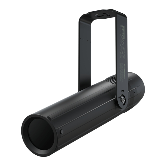
Page 9: Unit's Main Components
Unit’s main components Components description A Yoke with mounting holes Cooling unit C Optical holder tube Locking screw for yoke... -
Page 10: Back Panel Description
Back panel description Display Plus button Menu button Minus button Enter button DMX Out DMX In Power In... -
Page 11: Installation
. Installation Mechanical installation LEDko EXT + may be hung from an appropriate structure in any position or on tripod. If hanging the fixture from a lighting truss or similar, we recommend the use of an appropriate clamp “A”, as shown in the following diagram. -
Page 12: Adjusting Unit's Tilt
Adjusting unit’s tilt In order to adjust the tilt of the unit simply loose the screw “B” on the yoke, adjust side the tilt and lock the yoke by tightening the screw again. 4.4 Optical group, framing system and gobos Follow these steps in order to configure the optical group properly: 1. - Page 13 3. Loose the thumbscrews “E” of the two lenses to set them at desired position. Turn on the fixture and check if the desired focus and zoom lever are correct, then tighten the thumbscrews;...
- Page 14 4. It is possible to regulate the shutter blades “H” to achieve the desired shape, use the four thumb screws “I” that you can see behind the shutter blades to free or block them; Four blade framing system, each shutter blade is adjustable for radial position and angle.
- Page 15 5. It is possible to insert the gobo, to do so unscrew the thumb screws “I”, at this point it will be possible to extract the gobo holder “K”. Insert the gobo by loosening the 4 screws “L”, at this point we suggest you to unscrew 2 of them on one side in order to lift the gobo holder and insert the desired gobo “M”.
- Page 16 6. Use the hole that you can see above and under the projectors, in it there is a screw and by unscrewing it you can adjust the optical group’s position by rotating it, tighten the two screws symmetrically with each other in order to keep straight your optical group; 7.
-
Page 17: Powering Up
Note: in case of cable replacement, similar cable with comparable thermal resistant qualities must be used exclusively (cable 3 X 1,5 ø external 10 mm, rated 300/500V, tested to 2 KV, operating temperature -40°C + 180°C, Coemar cod. CV5311). Connection to mains power LEDko EXT + is equipped with two power connectors, one as input and one as output, which can be used to feed up to 8 (at 230 V) or 4 (at 115 V) fixtures. - Page 18 Warning!! The use of a thermal/magnetic circuit breaker is recommended. Strict adherence to regula- tory norms is strongly recommended. LEDko EXT + should not be powered through a dimmer as this may damage the internal switching power supply. Prior to connecting the device to mains power, ensure that the mains characteristics are within the recommended range for the use of LEDko EXT +.
-
Page 19: Control Signal Connections
. Control signal connections Control signal connection by XLR5 plugs The digital control signal is transmitted to the projector via a two pole cable screened in according to the International standards for DMX 512 data transmission. The connection must be serial, using connectors XLR5 male and female located on the back of LEDko EXT + labelled DMX512 IN e OUT. -
Page 20: Turning The Projector On
. Turning the projector on After having followed the preceding steps described, proceed with the power supply and turn on the projector connecting it to the mains power. The software version installed on the internal microprocessors will be shown on the display, sud- denly it will show the current DMX addressing. -
Page 21: Dmx Chart
DMX chart 8.1 DMX modes channels channels channels ↓ Master Dimmer Master Dimmer Spare Channel Dimmer Fine Strobe Special Function... -
Page 22: Dmx Chart 5, 1 Channels
DMX Chart 5, 1 channels type of channel function effect decimal percentage control 1 master dimmer proportional adjust luminous output intensity from 0 to 100% - 255 0% - 100% spare channel step no effect - 255 0% - 100% dimmer fine proportional fine dimmer control 16 bit... -
Page 23: Setup Via Rdm
Setup via RDM Quick guide to menu The LEDko EXT + required RDM (Remote Device Management) to set up fixtures. Using an RDM compliant DMX controller, you can communicate with all the fixtures on a data link without needing to connect to each fixture individually. RDM lets you set the DMX addresses of all the fixtures on the link, carry out fixture configuration and retrieve fixture data including details of any error that has been logged. -
Page 24: Rdm Error Chart
RDM Error Chart ERROR DESCRIPTION SOLUTION MEMORY Memory Reading Error Perform A “Factory Reset” HW MEMORY Memory Hardware Error Contact Coemar DMX ADDR DMX Addressing Error The Personality Dimension Exceeds 512 Channels NTC ERROR Temperature Sensor Check Wiring NTC Led Disconnected... -
Page 25: Display Panel Functions
Changing the preset settings made by Coemar can vary the functions of the projector so that it will respond differently to the controller; therefore carefully read about the functions described here before carrying out any possible selection. -
Page 26: Main Functions Menu
10.3 Main functions menu By pressing the “MENU” button you can enter the LEDko EXT + main menu. INTENSITY: intensity Allows to adjust the luminous output intensity from 0 to 255 (d: decimal units). STROBE: strobe Manually sets the strobe DMX channel. -
Page 27: Settings
10.4 Settings DIMMING CURVE: dimming curve exponential It allows the selection of exponential different dimmer curves: halogen exponential (default), halogen, standard, linear and standard logarithmic. linear logarithmic SMOOTH: smooth fast Allows to change the speed Fast of every dimming curve slow between FAST (standard), SLOW, VERY SLOW. - Page 28 LED OUTPUT: led output auto Manually sets the fan mode. auto AUTO: Fan with automatic studio operating speed to guarantee maximum light output in all SILENT conditions of use, ideal for live events, exhibitions and architectural installations. STUDIO: Fan at automatic operation speed with limited speed to guarantee silent operation of the product...
- Page 29 PERSONALITIES: PERSONALITIES 5 CH It is possible to choose 5 CH between 5, or 1 modalities, 1 CH in which the projector will operate. LOSS SIGNAL: loss signal MAINTAIN It is possible to choose maintain between “maintain” (this BLACKOUT function allows to keep the settings even in case of LOSS SIGNAL) and “blackout”...
-
Page 30: Display
10.5 Display REVERSE: reverse It allows to turn by 180° the reading of the display. When you chose “ON” wait the turn of the display without clicking. AUTO LOCK: AUTO LOCK Locks the keys. OFF: Auto Lock function in HOLD HOLD: Press any key for 3 seconds to unlock. - Page 31 BRIGHTNESS DISPLAY: brightness display Allows to change the brightness of the display (from 0 to 10). BRIGHTNESS KEY: brightness key Allows to change the brightness of the key (from 0 to 10).
-
Page 32: Measures
10.6 Measures TEMPERATURES: TEMPERATURES Shows the current ° F MIN NOW MAX temperature values of the LED: -°C -°C -°C fixture. BOARD: -°C -°C -°C LED: shows the LED module temperature. BOARD: shows the electronic board temperature. TEMPERATURES HISTORIES: TEMP histories Shows the history °... - Page 33 LED STATUS: led status Shows the percentage value of the LED status. led protection LED PROTECTION: Percentage of the maximum power in order to keep the projector in temperature. PSU VOLTAGE: psu voltage Shows the power supply voltage. LIFETIME: lifetime Shows the hour counter of LED: the fixture.
-
Page 34: Wi-Fi Menu (Optional)
. Wi-Fi Menu (OPTIONAL) 11.1 Wi-Fi WIFI ENABLE: WIFI ENABLE It allows enable all the Wi-Fi functions WIFI UNLINK: WIFI unlink sure? This function is used to disconnect the projector from the transmitter. -
Page 35: Special Function And Error Messages
If a malfunction occurs, LEDko EXT + has a self-diagnostic system that will show the error message on the display. The following table will explain in detail the most common errors. If, despite of suggested intervention, the problem persists, call the Coemar Service Center. Error code... -
Page 36: Accessories And Spare Parts
RME34/G last projector of the line) All the components of LEDko EXT + are available as spare parts from your Coemar dealer or Service. Accurate description of the fixture, model number and type will assist us in providing for your requirements in an efficient and effective manner. -
Page 37: Maintenance
. Maintenance 14.1 Firmware update The firmware of LEDko EXT + can be updates through the RDM protocol (ANSI E1.20). Contact Coemar assistance to receive the software and the device updater (AC10011A000). 14.2 Periodic cleaning Lenses Even a thin layer of dust can reduce the luminous output and alter the consistency of the beam. -
Page 38: And Answers
• Check DMX address of the unit. Help from Coemar Technical Services If you are having difficulties and your problem is not addressed by this document, contact Coemar Technical Services directly at one of this email address: info@coemar.com / service@coemar.com... - Page 39 User notes ......................................................................................................................................................................................................................................................................................................................................................................................................................
- Page 40 Information on disposal of the equipment The equipment at the end of its useful life must be disposed of at an appropriate recycling center for waste electrical and electronic equipment. The treatment and disposal of environmentally friendly, helps prevent potential negative environmental and health and promote the reuse and / or recycling of materials making up the equipment.
- Page 41 Coemar Lighting s.r.l. Via Carpenedolo 90 46043 Castiglione delle Stiviere, Mantova, Italy phone. +39 0376/1514412 - fax +39 0376/1514380 info@coemar.com Coemar reserves the right to change specifications without prior notice...
Need help?
Do you have a question about the LEDko EXT + and is the answer not in the manual?
Questions and answers