
Related Manuals for AEMC 565


Summary of Contents for AEMC 565
- Page 1 TRMS LEAKAGE CURRENT CLAMP-ON METER 1.800.561.8187 information@itm.com www. .com E N G L I S H User Manual...
- Page 2 Statement of Compliance Chauvin Arnoux , Inc. d.b.a. AEMC Instruments ® ® certifies that this instrument has been calibrated using standards and instruments traceable to international standards. We guarantee that at the time of shipping your instrument has met its published specifications.
-
Page 3: Table Of Contents
1.1 International Electrical Symbols .....4 1.2 Receiving Your Shipment .......4 1.3 Ordering Information ......4 2. PRODUCT FEATURES ....... 5 2.1 Description ..........5 2.2 Model 565 Control Features....6 2.3 LCD Display ...........7 2.4 Button Functions ........8 2.4.1 HOLD Button ......8 2.4.2 Backlight Button ......8 2.4.3 MAX Button .......9... - Page 4 4.8 Frequency Measuring Using Voltage Input ........23 5. MAINTENANCE ....... 24 5.1 Warning ..........24 5.2 Cleaning ..........24 5.3 Battery Replacement......25 Repair and Calibration ........26 Technical and Sales Assistance ......26 Limited Warranty ..........27 Warranty Repairs ..........27 1.800.561.8187 information@itm.com www. .com Clamp-on Meter Model 565...
-
Page 5: Introduction
Use extreme caution when measuring live systems with voltages greater than 60V or 30V • Use extreme care when working around bus bars and bare conductors. • Do not use the meter in over range/overload conditions (OL). • For accurate readings, change the battery when the symbol appears. 1.800.561.8187 information@itm.com www. .com Clamp-on Meter Model 565... -
Page 6: International Electrical Symbols
Save the damaged packing container to substantiate your claim. 1.3 Ordering Information Clamp-on Meter Model 565 ..... Cat. #2117.56 Includes meter, test leads, two 1.5V AAA (LR03) batter- ies, user manual and soft carrying case. 1.3.1 Accessories and Replacement Parts Leads, PTL-30 ........... -
Page 7: Product Features
(not the ground conductor). The vector sum of the load currents will cancel out, leaving the leakage current measured. The user may also use the Model 565 as a standard clamp-on meter to 100A , plus standard V , V ranges, resistance and continuity with a buzzer. In mA... -
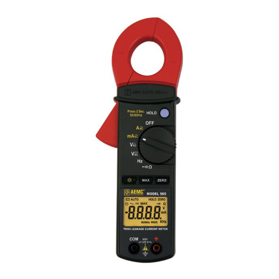
Page 8: Model 565 Control Features
2.2 Model 565 Control Features HOLD ZERO 1. Jaw assembly (Ø 1.10", 28mm) 2. Safety barrier anti-slip guard 3. Lever for jaw opening/closing 4. Backlight, Max hold and Zero buttons 5. LCD display 6. COM (Black) and Positive (Red) input terminal jack 1.800.561.8187 information@itm.com www. .com 7. Data hold button 8. -
Page 9: Lcd Display
Low Battery Auto-off Indicator AUTO Auto Range Max Hold HOLD Data Hold ZERO Zero Indicator KΩ Continuity and Resistance Voltage Indicator mA A Current Indicator Frequency Indicator 50/60Hz WIDE Filter Indicator Overrange 1.800.561.8187 information@itm.com www. .com Clamp-on Meter Model 565... -
Page 10: Button Functions
Note: This feature is active on A and mA ranges only. 2.4.2 Backlight Button Press the button once to turn the backlight on. Press 1.800.561.8187 information@itm.com www. .com it again to turn it off. When backlight is on, the meter will automatically turn the backlight off after approx 180 sec- onds (3 minutes). Clamp-on Meter Model 565... -
Page 11: Max Button
The reading is stored as a reference value for subsequent measurements. • To exit the Zero mode, press the ZERO button again. 2.4.5 Auto-OFF The Model 565 will automatically shut down if there is no activity for approximately 10 minutes . • To disable the Auto-OFF function, turn the rotary switch to OFF. • Press and hold down the ZERO button and set the rotary switch to any position other than OFF. -
Page 12: Specifications
1.2% Rdg ± 5cts (50 to 60Hz) 150Arms 2.5% Rdg ± 5cts (50 to 500Hz) 3.5% Rdg ± 10cts (500 to 3kHz) 100A* 10mA *80 to 100A: 5.0% Rdg ± 5cts (50-60Hz) Max Voltage to Ground: 600V 1.800.561.8187 information@itm.com www. .com Clamp-on Meter Model 565... - Page 13 0.1Ω < 35Ω ± 25Ω 3.3V 660Vrms Overload: is displayed and buzzer will sound Nominal Sample Rate: 2 measurements/sec approx 1.800.561.8187 information@itm.com www. .com MAX Sample Rate: 100 ms Power Supply: Two 1.5V AAA (LR03) alkaline batteries Clamp-on Meter Model 565...
-
Page 14: Mechanical Specifications
Dimensions: 8.5 x 2.5 x 1.18" (218 x 64 x 30mm) Weight: 10 oz (280g) with batteries 3.3 Environmental Specifications Altitude: 2000m (6000ft) Operating Temperature: 32° to 104°F (0° to 40°C), <80% RH, non-condensing Storage Temperature: 14° to 140°F (-10° to 60°C), <70% RH, battery removed 3.4 Safety Specifications EN 61010-1 Ed. 2001, EN 61010-2-032 Ed. 2003 600V, Cat. III Double Insulation; Pollution Degree 2 Altitude <2000m 1.800.561.8187 information@itm.com www. .com Clamp-on Meter Model 565... -
Page 15: Operation
• DO NOT touch the voltage input jacks when measuring current. • DO NOT measure current while the test leads are connected to the input jacks. • DO NOT touch the jaw’s magnetic core when measuring voltage. 1.800.561.8187 information@itm.com www. .com Clamp-on Meter Model 565... -
Page 16: Ac Current Measurement
• Press the lever to open the jaws. • Clamp the jaws around the conductor to be measured. • To freeze the reading, push the HOLD button. Push the button again to release. Immediately unclamp the meter from the conductor if " " is displayed. 1.800.561.8187 information@itm.com www. .com Clamp-on Meter Model 565... - Page 17 Leakage Current Measurement Examples Ground Single Phase Load 1. Measure branch leakage current (leakage from all loads on branch) 1.800.561.8187 information@itm.com www. .com 2. Measure leakage current on load 3. Measure leakage current on load to Ground/Earth Clamp-on Meter Model 565...
- Page 18 Two-Phase Load Three-Phase - 3 Wire Load 1. Measure branch leakage current (leakage from all loads on branch) 2. Measure leakage current on load 1.800.561.8187 information@itm.com www. .com 3. Measure leakage current on load to Ground/Earth Clamp-on Meter Model 565...
- Page 19 2. Measure leakage current on load 3. Measure leakage current on load to Ground/Earth NOTE: These drawings are for reference only. Jaw size may not permit all measurements. Contact AEMC Instruments for other ® leakage current probes.
-
Page 20: Ac Volt Measurement
• Turn the rotary range switch to the range. • Insert the red test lead to the red "+" input jack and the black lead to the black "COM" input jack. • Bring the test probe tips into contact with the test points. WARNING: Immediately remove the leads from the conductor if " " is displayed. 1.800.561.8187 information@itm.com www. .com Clamp-on Meter Model 565... -
Page 21: Dc Volt Measurement
• Turn the rotary range switch to the range. • Insert the red test lead to the red "+" input jack and the black lead to the black "COM" input jack. • Bring the test probe tips into contact with the test points. WARNING: Immediately remove the leads from the conductor if " " is displayed. 1.800.561.8187 information@itm.com www. .com Clamp-on Meter Model 565... -
Page 22: Resistance Measurement
(dead circuit). Also make sure the cur- rent is fully discharged. This may be checked by using the voltage functions. 1.800.561.8187 information@itm.com www. .com Clamp-on Meter Model 565... -
Page 23: Continuity Measurement
(dead circuit). Also make sure the current is fully discharged. This may be checked by using the voltage functions. Short circuit Open circuit with beep no beep 1.800.561.8187 information@itm.com www. .com Clamp-on Meter Model 565... -
Page 24: Frequency Measuring Using Current Input
4.7 Frequency Measuring Using Current Input • Turn the rotary range switch to the range. • Press the lever to open the jaws. • Clamp the jaws around the conductor to be mea- sured. WARNING: When performing a Frequency measurement, you should either use the voltage signal or current signal, but never both together. If both sources are applied an error reading will occur. 1.800.561.8187 information@itm.com www. .com Clamp-on Meter Model 565... -
Page 25: Frequency Measuring Using Voltage Input
• Insert red test lead to the red "+" input jack and the black lead to the black "COM" input jack. • Bring the test probe tips into contact with the sample under test. WARNING: When performing a Frequency measurement, you should either use the voltage signal or current signal, but never both together. If both sources are applied an error reading will occur. 1.800.561.8187 information@itm.com www. .com Clamp-on Meter Model 565... -
Page 26: Maintenance
5.2 Cleaning • To clean the probe, wipe the case with a damp cloth and mild detergent. • Do not use abrasives or solvents. • Do not get water inside the case. This may lead to electrical shock or damage to the instrument. • Thoroughly dry all parts before using again. 1.800.561.8187 information@itm.com www. .com Clamp-on Meter Model 565... -
Page 27: Battery Replacement
It is recommended to replace both batteries at the same time. • The meter must be in the OFF position and discon- nected from any circuit or input. • Place the meter face down and loosen the battery cover screw with a flat head screwdriver. • Replace the batteries with two fresh 1.5V AAA (LR03) batteries. • Replace the battery compartment cover and tighten down the screw. 1.800.561.8187 information@itm.com www. .com Clamp-on Meter Model 565... -
Page 28: Repair And Calibration
Chauvin Arnoux , Inc. d.b.a. AEMC Instruments ® ® 200 Foxborough Boulevard Foxborough, MA 02035, USA Phone: (800) 343-1391 or (508) 698-2115 Fax: (508) 698-2118 E-mail: techsupport@aemc.com www.aemc.com NOTE: Do not ship Instruments to our Foxborough, MA 1.800.561.8187 information@itm.com address. www. .com Clamp-on Meter Model 565... -
Page 29: Limited Warranty
Limited Warranty The Model 565 is warranted to the owner for a period of one year from the date of original purchase against defects in manufacture. This limited warranty is given by AEMC Instruments, not by the ® distributor from whom it was purchased. This warranty is void if... -
Page 30: Clamp-On Meter Model
NOTES: 1.800.561.8187 information@itm.com www. .com Clamp-on Meter Model 565... - Page 31 1.800.561.8187 information@itm.com www. .com...
- Page 32 06/10 99-MAN 100287 v5 1.800.561.8187 information@itm.com www. .com Chauvin Arnoux , Inc. d.b.a. AEMC Instruments ® ® 15 Faraday Drive • Dover, NH 03820 USA www.aemc.com...
Need help?
Do you have a question about the 565 and is the answer not in the manual?
Questions and answers