
Subscribe to Our Youtube Channel
Related Manuals for KSB CalioTherm Pro 25


Summary of Contents for KSB CalioTherm Pro 25
- Page 1 Circulator / High-efficiency Drinking Water Pump CalioTherm Pro Also applies to Calio-Therm Installation/Operating Manual...
- Page 2 All rights reserved. The contents provided herein must neither be distributed, copied, reproduced, edited or processed for any other purpose, nor otherwise transmitted, published or made available to a third party without the manufacturer's express written consent. Subject to technical modification without prior notice. © KSB SE & Co. KGaA, Frankenthal 2023-10-13...
-
Page 3: Table Of Contents
Contents Contents Glossary .............................. 5 General.............................. 6 Principles ................................ 6 Target group.............................. 6 Other applicable documents.......................... 6 Symbols ................................ 6 Key to safety symbols/markings........................ 7 Safety .............................. 8 General................................ 8 Intended use .............................. 8 Personnel qualification and training....................... 9 Consequences and risks caused by non-compliance with this manual ............ 9 Safety awareness .............................. 9 Safety information for the operator/user ....................... 9 Safety information for maintenance, inspection and installation .............. 10... - Page 4 Contents 6.2.4 Maximum operating pressure ...................... 37 6.2.5 Fluid handled ............................ 37 Shutdown/storage/preservation ........................ 38 6.3.1 Shutdown ............................ 38 6.3.2 Measures to be taken for shutdown.................... 38 Returning to service ............................ 39 Operation.............................. 40 Control panel .............................. 40 7.1.1 Display ............................... 41 Operating modes............................ 42 7.2.1 Information on settings ........................
-
Page 5: Glossary
Glossary Glossary Discharge line The pipeline which is connected to the discharge nozzle Pump Machine without drive, additional components or accessories Pump set Complete pump set consisting of pump, drive, additional components and accessories Setback operation Setback Operation avoids running the pump set at an unchanged control curve during the night. -
Page 6: General
The name plate indicates the type series and size as well as the main operating data. They uniquely identify the pump (set) and serve as identification for all further business processes. In the event of damage, immediately contact your nearest KSB service facility to maintain the right to claim under warranty. 1.2 Target group This operating manual is aimed at the target group of trained and qualified specialist technical personnel. -
Page 7: Key To Safety Symbols/Markings
1 General 1.5 Key to safety symbols/markings Table 3: Definition of safety symbols/markings Symbol Description DANGER DANGER This signal word indicates a high-risk hazard which, if not avoided, will result in death or serious injury. WARNING WARNING This signal word indicates a medium-risk hazard which, if not avoided, could result in death or serious injury. -
Page 8: Safety
2 Safety 2 Safety All the information contained in this section refers to hazardous situations. DANGER In addition to the present general safety information the action-related safety information given in the other sections must be observed. 2.1 General ▪ This operating manual contains general installation, operating and maintenance instructions that must be observed to ensure safe operation of the system and prevent personal injury and damage to property. -
Page 9: Personnel Qualification And Training
2 Safety 2.3 Personnel qualification and training All personnel involved must be fully qualified to transport, install, operate, maintain and inspect the equipment this manual refers to. The responsibilities, competence and supervision of all personnel involved in transport, installation, operation, maintenance and inspection must be clearly defined by the operator. -
Page 10: Safety Information For Maintenance, Inspection And Installation
2 Safety 2.7 Safety information for maintenance, inspection and installation ▪ Modifications or alterations of the pump (set) are only permitted with the manufacturer's prior consent. ▪ Use only original spare parts or parts/components authorised by the manufacturer. The use of other parts/components can invalidate any liability of the manufacturer for resulting damage. -
Page 11: Transport/Storage/Disposal
1. On transfer of goods, check each packaging unit for damage. 2. In the event of in-transit damage, assess the exact damage, document it and notify KSB or the supplying dealer and the insurer about the damage in writing immediately. -
Page 12: Placing The Pump Set Down
3 Transport/Storage/Disposal 3.2.1 Placing the pump set down WARNING Insufficient stability Risk of crushing hands and feet! ▷ During assembly/dismantling, secure the pump (set)/pump parts to prevent tilting or tipping over. Place the pump set down as illustrated. Fig. 3: Placing the pump set down safely 3.3 Storage/preservation CAUTION Damage during storage due to humidity, dirt or vermin... -
Page 13: Return To Supplier
Indicate any safety measures and decontamination measures taken. NOTE If required, a blank certificate of decontamination can be downloaded from the following web site: www.ksb.com/certificate_of_decontamination 3.5 Disposal DANGER Strong magnetic field in the pump rotor area Danger of death for persons with pacemaker! -
Page 14: Description
▪ Pump for use in drinking water circulation systems to DVGW-W551 4.2 Product information as per Regulation No. 1907/2006 (REACH) For information as per European chemicals regulation (EC) No. 1907/2006 (REACH) see https://www.ksb.com/en-global/company/corporate-responsibility/reach. 4.3 Designation Example: CalioTherm Pro 25-80 Table 5: Designation key Code Description CalioTherm Pro... -
Page 15: Name Plate
Class F IPX4D 3,5 - 180 W P/N: 291348XX S/N: 291348XX-B202301-XXXX1 Made in Turkey | KSB SE & Co. KGaA Johann-Klein-Str. 9 67227 Frankenthal (Germany) Fig. 4: Name plate (example) 1 Type series, size 7 Production number 2 Mains voltage, frequency... - Page 16 ▪ Operating status shown on the display ▪ Error codes indicated on the display ▪ Configurable general fault message and "in operation" message (volt-free changeover contacts) ▪ Serial digital Modbus RTU interface ▪ Service interface for KSB ServiceTool CalioTherm Pro 16 of 76...
-
Page 17: Configuration And Function
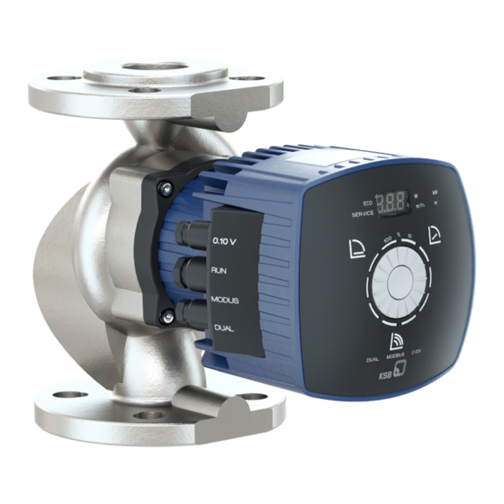
4 Description 4.6 Configuration and function Fig. 5: Illustration of the pump set 1 Two-piece thermal insulation shell 7 Discharge nozzle 2 Control panel 8 Radial plain bearing 3 Connections for control cables 9 Impeller 4 Display 10 Motor shaft 5 Control element (dial and control 11 Motor button) 6 Connections for power supply, "in... -
Page 18: Noise Characteristics
4 Description 4.7 Noise characteristics Average sound pressure level ≤ 40 dB (A) 4.8 Scope of supply Depending on the model, the following items are included in the scope of supply: ▪ Pump set ▪ Two-piece thermal insulation shell ▪ Gaskets ▪... -
Page 19: Installation At Site
5 Installation at Site 5 Installation at Site 5.1 Safety regulations DANGER Installation in potentially explosive atmospheres Explosion hazard! ▷ Never install the pump in potentially explosive atmospheres. ▷ Observe the information given in the data sheet and on the name plates of the pump system. -
Page 20: Installing The Pump Set
5 Installation at Site 5.3 Installing the pump set DANGER Leakage at the pump Leakage of hot fluids! ▷ Fit the sealing elements and make sure they are positioned correctly. CAUTION Fluid entering the electronic system housing Damage to the pump set! ▷... - Page 21 5 Installation at Site Positioning the control panel WARNING Insufficient stability Risk of crushing hands and feet! ▷ During assembly/dismantling, secure the pump (set)/pump parts to prevent tilting or tipping over. Fig. 6: Placing the pump set down safely The control panel can be turned. Positioning must be carried out with the pump set removed from the system.
- Page 22 5 Installation at Site Flanged pump 1. Position the pump set as indicated in an easily accessible place. ð An arrow on the pump casing and thermal insulation shell indicates the direction of flow. 2. Accurately insert the sealing element. 3.
-
Page 23: Connecting The Piping
5 Installation at Site 5.4 Connecting the piping WARNING Hot surface Risk of burns ▷ Never touch a pump set when it is in operation. WARNING Impermissible loads acting on the pump nozzles Risk of burns by hot fluids escaping! ▷... -
Page 24: Fitting The Enclosure/Insulation
5 Installation at Site 5.5 Fitting the enclosure/insulation WARNING The pump takes on same temperature as the fluid handled Risk of burns! ▷ Insulate the pump casing. Fit protective equipment. CAUTION Heat build-up at motor housing and electronic system housing Pump overheating! ▷... -
Page 25: Connecting The Electric Cables
5 Installation at Site DANGER Hazardous electrical voltage when the covers of the terminal wiring compartments are removed Danger of death from electric shock! ▷ For working on the terminals, switch off the power supply at least 5 minutes prior to commencing work and ensure that it cannot be switched on again unintentionally. - Page 26 5 Installation at Site The left side has 4 connection options and 3 cable glands. If all 4 connections are to be used, run the control cables of connections 2 and 3 through the cable gland in the middle. ü The mains voltage at the site has been verified against the data on the name plate.
- Page 27 ▪ Pump not in operation = rotor not rotating, no flow (alarm not active) ▪ Pump in operation = rotor rotating (alarm not active) For configuring and inverting use the KSB ServiceTool as described in the KSB ServiceTool supplementary operating manual (reference number 1157.801).
- Page 28 5 Installation at Site Fig. 11: Wiring diagram for the general fault message No general fault message or no power supply / alarm not active General fault message (rotor not rotating) / alarm active NC contact, normally closed and electrically conductive connection to COM COM Reference potential for either contact that is closed NO contact, normally open and not electrically conductive connection to COM 5.6.1.4 External analog 0 - 10 V DC signal...
- Page 29 5 Installation at Site 5.6.1.5 Remote ON/OFF Fig. 13: RUN terminal pair Signal 5 V (+) 0 V GND (-) ü The wiring diagram is available. (ð Section 10.2, Page 71) 1. Unscrew the cable glands (IPX4D). 2. Wire the external signal (volt-free switching contact) to the RUN terminal pair integrated in the pump set.
- Page 30 5 Installation at Site Connection to a building management system (BMS) Wire the bus terminating Modbus master resistor to the master / enable Modbus Modbus network cable with defined wave impedance (e.g. Ethernet cable) Address 1 Modbus Address n-1 0-10 V Modbus Address n DUAL...
- Page 31 5 Installation at Site Parameter Description/value Protocol Modbus RTU standard Data format ▪ 8 data bits ▪ Parity EVEN / ODD / NONE ▪ 1 stop bit Modbus address ID #1 to #247 selectable (ID #17 = factory setting) ü The mains voltage at the site has been verified against the data on the name plate.
- Page 32 Data line connections External 0-10 V Remote ON/OFF Terminating resistor for Modbus cable (DIP switches) Modbus or KSB ServiceTool Dual-pump configuration The terminating resistor is enabled when the corresponding pump-integrated DIP switch in the terminal wiring compartment next to the Modbus terminal pair is enabled.
- Page 33 5 Installation at Site 5.6.1.7 Connecting dual-pump configurations Wire the two pumps to each other with a suitable network cable (wave impedance 120 Ω), via the terminal pairs DUAL (a5). Setting Make sure the settings and wiring of both pumps are identical to ensure that the changeover from duty pump to stand-by pump will not have any impact on the duty point and operating mode.
-
Page 34: Commissioning/Start-Up/Shutdown
6 Commissioning/Start-up/Shutdown 6 Commissioning/Start-up/Shutdown 6.1 Commissioning/Start-up 6.1.1 Prerequisites for commissioning/start-up Before commissioning/starting up the pump set, make sure that the following conditions are met: ▪ The pump set has been properly connected to the power supply and is equipped with all protection devices. (ð Section 5.6, Page 24) ▪... -
Page 35: Start-Up
6 Commissioning/Start-up/Shutdown 6.1.3 Start-up DANGER Non-compliance with the permissible pressure and temperature limits if the pump is operated with the suction and discharge lines closed. Hot fluids escaping! ▷ Never operate the pump with the shut-off elements in the suction line and/or discharge line closed. -
Page 36: Operating Limits
6 Commissioning/Start-up/Shutdown 6.2 Operating limits DANGER Non-compliance with operating limits for pressure, temperature, fluid handled and speed Hot fluids escaping! ▷ Comply with the operating data indicated in the data sheet. ▷ Avoid prolonged operation against a closed shut-off element. ▷... -
Page 37: Maximum Operating Pressure
6 Commissioning/Start-up/Shutdown 6.2.4 Maximum operating pressure CAUTION Permissible operating pressure exceeded Damage to connections and seals! ▷ Never exceed the operating pressure specified in the data sheet. The maximum operating pressure equals 6 or 10 bar, depending on the design variant. See name plate. (ð Section 4.4, Page 15) 6.2.5 Fluid handled 6.2.5.1 Permissible fluids to be handled CAUTION... -
Page 38: Shutdown/Storage/Preservation
6 Commissioning/Start-up/Shutdown 6.2.5.3 Fluid temperature CAUTION Incorrect fluid temperature Damage to the pump (set)! ▷ Only operate the pump (set) within the temperature limits indicated. Table 15: Temperature limits of the fluid handled Permissible fluid temperature Value [°C] Maximum Minimum The fluid temperature has an impact on the minimum inlet pressure. (ð Section 6.2.3, Page 36) 6.3 Shutdown/storage/preservation 6.3.1 Shutdown... -
Page 39: Returning To Service
6 Commissioning/Start-up/Shutdown 6.4 Returning to service WARNING Failure to re-install or re-activate protective devices Risk of injury from moving parts or escaping fluid! ▷ As soon as the work is completed, properly re-install and re-activate any safety- relevant devices and protective devices. For returning the equipment to service, observe the sections on commissioning/start- up (ð Section 6.1, Page 34) and the operating limits (ð Section 6.2, Page 36) . -
Page 40: Operation
7 Operation 7 Operation 7.1 Control panel All settings are made using the control element on the housing front. The control element consists of a dial and a control button. The control button is arranged in the middle of the dial and can be pressed down. Setpoint values can be adjusted by turning the dial in increments down to a minimum of 0 %. - Page 41 7 Operation 7.1.1 Display The flow rate, the electrical input power and the head are shown as 3-digit numbers on the integrated display. The display alternates in 5-second intervals between these values with the corresponding units. The flow rate and the head are displayed as numbers with one decimal place;...
-
Page 42: Information On Settings
The head setpoint is determined by the set operating mode and the selected setpoint. The functionality of the hydraulic controller and its settings via the KSB ServiceTool are described in the KSB ServiceTool supplementary operating manual (reference number 1157.801). -
Page 43: Constant-Pressure Control
7 Operation 7.2.2 Constant-pressure control Application ▪ Drinking water circulation systems ▪ Underfloor heating systems ▪ Solar pumps Solar pumps require a high operating pressure to pump sufficient fluid through the heat exchanger. Proportional-pressure Control is not necessary as the thermostatic valves do not impact on the characteristic curve. - Page 44 7 Operation Step 4 a: Confirming the current setpoint ▪ Press the control button. Step 4 b: Changing the setpoint ▪ Turn the dial and set the required setpoint in increments of 1 % within the range from 0 % to 100 %. – Turning it clockwise increases the setpoint; turning it anti- clockwise decreases the setpoint.
-
Page 45: Proportional-Pressure Control
7 Operation 7.2.3 Proportional-pressure control Application ▪ Heating systems with a radiator The higher the flow rate, the higher the system’s resistance. This is corrected by the pump set automatically increasing the head setpoint. When setting the setpoint ensure that the selected control curve is suitable for the system characteristic curve: ▪... - Page 46 7 Operation Step 3: Activating the Proportional-pressure Control operating mode ▪ Press the control button. – The number of flashing LED segments shows the setpoint which has last been set. Step 4 a: Confirming the current setpoint ▪ Press the control button. Step 4 b: Changing the setpoint ▪...
-
Page 47: Eco Mode
7 Operation 7.2.4 Eco Mode Function Eco Mode operating mode is an energy-efficient alternative to Proportional-pressure Control. Eco Mode is based on a linear characteristic curve rather than a quadratic one. The consequences on the process are illustrated at the example of size 25-100 in the figure below: [m /h] Fig. 24: Eco Mode and proportional pressure, example of a size 25-100 pump... - Page 48 7 Operation Table 20: Selecting Eco Mode and the setpoint Step 1: Activating the setting mode ▪ Press and hold the control button for 3 seconds. – The operating mode which has last been selected will start flashing. Step 2: Selecting the Eco Mode operating mode ▪...
-
Page 49: Open-Loop Control
7 Operation 7.2.5 Open-loop control Function In Open-loop Control operating mode the pump runs at a set speed. The speed can be set to one of 100 speed levels. Fig. 26: Open-loop Control function, running at speed level 2 Setting Press the control button to activate the display from idle mode. The display will show the current operating mode as well as, in alternation, the electrical input power and the flow rate. -
Page 50: Temperature-Governed Differential Pressure Control
The operating mode can be activated via the KSB ServiceTool. The functionality of the temperature-governed differential pressure control and its settings are described in the KSB ServiceTool supplementary operating manual (reference number 1157.801). -
Page 51: Functions
The digital input is factory-set to start up and stop the pump set. The digital input can also be configured. For the configuration use the KSB ServiceTool as described in the KSB ServiceTool supplementary operating manual (reference number 1157.801). Table 23: Pump start and stop... - Page 52 1,5 V 10 V U [V DC] Fig. 28: Analog 0 -10 V signal as setpoint input for the pump set Use the KSB ServiceTool for setting the limits and parameters for the following functions: ▪ Starting up the pump ▪ Stopping the pump ▪...
-
Page 53: Dual-Pump Operation (Dual)
▪ The overall efficiency of the system with two pump sets running in parallel is higher than with a single pump running. ▪ The set head is not reached by one pump alone. The Peak Load function is described in the KSB ServiceTool supplementary operating manual (reference number 1157.801). Setting Press the control element to activate the display from idle mode. - Page 54 7 Operation NOTE Connected pump sets will use the settings of the other pump sets. This does not apply to the Modbus address. Table 27: Activating and de-activating the Dual-pump Operation (DUAL) operating mode Step 1: Activating the functions (DUAL, Modbus, 0 - 10 V) setting mode ▪...
- Page 55 7 Operation Table 28: Overview of Modbus operating parameters Parameter description Register Length Type/format Unit Access [byte] Error value, bit code 07 D0 00 02 UINT16 Bit 0 = error code E01 Bit 1 = error code E02 Bit 2 = error code E03 Bit 3 = error code E04 Bit 4 = error code E05 Bit 5 = error code E06...
- Page 56 Both pumps programmed as "left pump" Error value 2, bit code Externally forced flow Externally forced flow in pumping direction Backflow through the pump Further information in the KSB ServiceTool supplementary operating manual (reference number 1157.801) CalioTherm Pro 56 of 76...
-
Page 57: Modbus
7 Operation NOTE Error values I18 and I19 serve as information; error values I10, E11 and I14 are warnings. The pump set does not stop in this case. The error value is displayed until the corresponding error has been resolved. Error value E05 reduces the speed until no overload is detected any more. - Page 58 7 Operation NOTE The pump is delivered with the terminal pair RUN bridged. Setting For activating/de-activating the Modbus operating mode and adjusting the Modbus communication settings, connect the pump to a Modbus network with a suitable, commercial, shielded data cable. Press the control element to activate the display from idle mode.
-
Page 59: Ramps
To prevent pressure surges this dynamic is limited while the pump set is started up / stopped or when the pump controller changes the setpoint in large increments. The ramps' dynamic is set via the KSB ServiceTool. The ramps' function and settings are described in the KSB ServiceTool supplementary operating manual (reference number 1157.801). -
Page 60: General Fault Messages
"left pump". Externally forced flow in pumping direc- Information Pump keeps running. tion Backflow through the pump Information Pump keeps running. Further information in the KSB ServiceTool supplementary operating manual (reference number 1157.801) CalioTherm Pro 60 of 76... -
Page 61: Additional Functions
7 Operation 7.4 Additional functions 7.4.1 Locking the control panel Table 36: Locking / unlocking the control panel Step 1: Activating the additional function setting mode ▪ Press and hold the control button for 10 seconds. – The additional functions setting mode is active. –... -
Page 62: Setback Operation
▪ The fluid temperature rises by 3 °C. ▪ The pump set has been in night mode for more than 7 hours. Settings The Setback Operation function and its settings are made via the KSB ServiceTool and are described in the KSB ServiceTool supplementary operating manual (reference number 1157.801). -
Page 63: Dynamic Control
Settings The Setback Operation function and its settings are made via the KSB ServiceTool and are described in the KSB ServiceTool supplementary operating manual (reference number 1157.801). - Page 64 7 Operation Table 38: Activating and disabling Dynamic Control Step 1: Activating the additional function setting mode ▪ Press and hold the control button for 10 seconds. – The additional functions setting mode is active. Step 2: Selecting Dynamic Control ▪ Turn the dial and select the required function. dc0 / dc1 Step 3: Activating the setting mode ▪...
-
Page 65: Venting
7 Operation 7.4.4 Venting Function For venting the pump the RUN contact must be bridged and the pump set must be in operation. When the Venting function is activated, the pump set runs through a pre-set speed profile. The pump set automatically reduces and increases the setpoint and the speed. -
Page 66: Information
7 Operation 7.4.5 Information Table 40: Displaying information Step 1: Activating the additional function setting mode ▪ Press and hold the control button for 10 seconds. – The additional functions setting mode is active. Step 2: Selecting Information ▪ Turn the dial and select the required function. Step 3: Confirming the setting ▪... -
Page 67: Servicing/Maintenance
Any repairs on the pump must only be performed by one of our authorised service partners. Find your contact in the attached Addresses booklet or visit https://www.ksb.com/ en-global/contact. The pump set is almost maintenance-free. If the pump set has not been in operation for a prolonged period of time or if the system is severely contaminated, the pump rotor can become blocked. - Page 68 8 Servicing/Maintenance DANGER Pump acting as a generator when running in reverse Danger to life from hazardous induction voltage at the motor terminals! ▷ Prevent the fluid from flowing back by closing the shut-off elements. WARNING Strong magnetic field Danger of crushing injuries when pulling out the pump rotor! Strong magnetic field can suddenly pull the pump rotor back into its original position! Danger of magnetic parts near the pump rotor being attracted!
-
Page 69: Trouble-Shooting
9 Trouble-shooting 9 Trouble-shooting WARNING Improper work to remedy faults Risk of injury! ▷ For any work performed to remedy faults, observe the relevant information given in this operating manual and/or in the product literature provided by the accessories manufacturer. If problems occur that are not described in the following table, consultation with the customer service is required. -
Page 70: E17 Externally Forced Flow
▪ Incorrect rotor angle caused by externally forced flow. Alarm E17 is active. ▪ Broken wire of temperature sensor ▪ Have it checked by KSB's service. (NTC thermistor) in the motor ▪ Firmware not compatible ▪ Carry out a firmware update. -
Page 71: Related Documents
10 Related Documents 10 Related Documents 10.1 Exploded view with list of components 01-44 81-59 Fig. 30: Exploded view Table 43: List of components Part No. Description Part No. Description 01-44 Rotor Pump casing 81-59 Stator Joint ring Heat sink including frequency inverter 10.2 Wiring diagram Fig. 31: Wiring diagram Connections for control cables... -
Page 72: Eu Declaration Of Conformity
11 EU Declaration of Conformity 11 EU Declaration of Conformity Manufacturer: KSB SE & Co. KGaA Johann-Klein-Straße 9 67227 Frankenthal (Germany) This EU Declaration of Conformity is issued under the sole responsibility of the manufacturer. The manufacturer herewith declares that the product:... -
Page 73: Eu Declaration Of Conformity
12 EU Declaration of Conformity 12 EU Declaration of Conformity Manufacturer: KSB SE & Co. KGaA Johann-Klein-Straße 9 67227 Frankenthal (Germany) This EU Declaration of Conformity is issued under the sole responsibility of the manufacturer. The manufacturer herewith declares that the product:... -
Page 74: Index
Index Index Applications 8 Return to supplier 13 Automatic functions 16 Returning to service 39 Bearings 15 Safety 8 Safety awareness 9 Scope of supply 18 Commissioning 34 Shutdown 38 Connections 15 Signalling and display functions 16 Start-up 35 Storage 12, 38 Design 15 Designation 14 Disposal 13 Transport 11 Drive 15 Warnings 7 Event of damage 6 Warranty claims 6 Faults Causes and remedies 69 Fluid handled Density 37... - Page 76 KSB SE & Co. KGaA Johann-Klein-Straße 9 • 67227 Frankenthal (Germany) Tel. +49 6233 86-0 www.ksb.com...
Need help?
Do you have a question about the CalioTherm Pro 25 and is the answer not in the manual?
Questions and answers