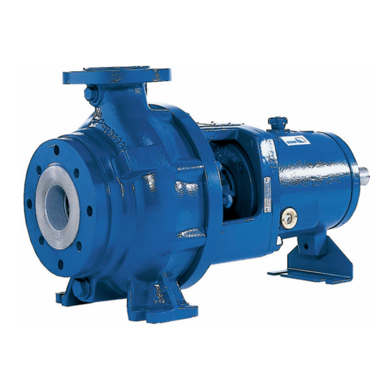
KSB KWP Manual
Hide thumbs
Also See for KWP:
- Installation & operating manual (100 pages) ,
- Installation & operating manual (78 pages)
Table of Contents
Advertisement
Quick Links
Contents
Point no.Description
1
1.1
2
2.1
2.2
2.3
2.4
2.4.1
2.4.2
2.5
2.6
2.7
3
3.1
3.1.1
3.1.2
3.1.2.1
3.1.2.2
3.1.2.3
3.1.2.4
3.1.2.5
3.1.2.6
3.1.3
3.1.4
3.2
3.3
4
4.1
4.2
4.2.1
4.2.2
4.2.2.1
4.3
5
5.1
5.1.1
5.1.2
5.1.2.1
5.1.3
5.2
5.3
5.3.1
5.3.2
for one year of operation
5.3.3
5.4
5.4.1
6
6.1
6.2
Page no.
1
1
1
1
1
1
1
2
2
2
2
2
2
2
2
3
3
3
3
3
4
4
4
4
5
5
5
5
5
5
5
5
5
5
5
5
5
6
7
7
7
7
7
8
8
10
10
10
KWP
Advertisement
Table of Contents

Summary of Contents for KSB KWP
-
Page 1: Table Of Contents
Contents Point no.Description Page no. General Handling Installation Foundation Base frame and pump Alignment of pump and driver Connecting the piping 2.4.1 Auxillary connections 2.4.2 Vacuum balance line Coupling guard Measuring instruments Final check Commissioning, start up shut down Preliminary remarks regarding commissioning 3.1.1 lubricants 3.1.2... -
Page 2: General
General min. 50 mm Your centrifugal pumps will only give you completely trouble free and satisfactory service on condition that it is installed with due care and properly maintained. It is absolutely essential that the instructions contained in this manual be scrupulously observed, and that the pumps are not operated under conditions which differ from those specified under our >800... -
Page 3: Auxillary Connections
2.4.1 Auxiliary connections. not to be supplied by us, it must be provided by the pump operator. The auxiliary connections required for your pump (sealing liquid, as the case may be ) are indicated on the installation Measuring instruments drawing. For sizes and details of connections see Table-1 Each pump should be equipped with two pressure gauges, one at the suction nozzle and other at the discharge nozzle;... -
Page 4: Shaft Seal
3.1.2 Shaft seal moderately with the aid of the stuffing box gland (452) and of the nuts. Then the nuts should be slackened again by one to The shaft is sealed at its exit through the casings by soft packed two complete turns, and thereafter tightened lightly by hand. -
Page 5: Alternate Packing Arrangements Available
3.1.2.6 Instructions for stuffing box packing arrangement Bearing Pump di φ da φ Bracket size An instruction plate depicting the required packing arrangement in the picture form is rivetted on the bearing bracket lantern. 65-200 P35/80 80-250 P45/120 65-315 100-400 P55/140 12.5 150-315... -
Page 6: Shutdown
Shutdown prevent the penetration of moisture (not applicable to pumps fitted with mechanical seals) Close discharge valve Switch off motor and check that the pump run down smoothly CAUTION : and gradually to a standstill. Only use acid free oils and greases when preserving the pump. Close suction valve. -
Page 7: Reassembly
O Ring 412.03. Pull off the impeller with a special screw threads. puller type device of KSB make as shown in fig.9. Remove The following points should be carefully observed. the key. -
Page 8: Spares
5.3.1 Ordering spare parts. When ordering spare parts, always please specify the following data : Pump type : (KWP in this case) Part No. : Works order No.: The above data are stamped on the data plate fixed on the pump. -
Page 9: Sectional Drawing & List Of Components
Sectional drawings and list of components 5.4.1 Standard bearing assembly... - Page 10 List of components Part No. Description Part No. Description Casing Neck ring 135.1 Wear Plate Lantern ring Pressure cover Gland packing Support feet Splash ring Shaft Shaft protection sleeve Impeller Constant level oiler 321.1 Deep groove ball bearing Vent plug Cylindrical roller bearing Impeller cap Bearing bracket...
-
Page 11: Faults
- Increase voltage power supply pressure. 11. Excessive wear of the pump internal Please refer to KSB - Replace worn components by new ones. This fault can also be remedied by altering the impeller diameter. - Page 12 Notes :...


Need help?
Do you have a question about the KWP and is the answer not in the manual?
Questions and answers