
Related Manuals for KSB Amacan K


Summary of Contents for KSB Amacan K
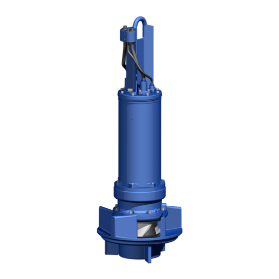
- Page 1 Submersible Pump in Discharge Tube Amacan K Size: 700-330 to 1200-630 4 Poles: 95 4.N 6 Poles: 60 6.N to 440 6.N 8 Poles: 90 8.N to 185 8.N 10 Poles: 40 10.N to 75 10.N Installation/Operating Manual Mat. No.: 01117570...
- Page 2 All rights reserved. The contents provided herein must neither be distributed, copied, reproduced, edited or processed for any other purpose, nor otherwise transmitted, published or made available to a third party without the manufacturer's express written consent. Subject to technical modification without prior notice. © KSB SE & Co. KGaA, Frankenthal 27/06/2022...
-
Page 3: Table Of Contents
Installing the pump set without support rope................. 27 5.3.2 Installing the pump set with a support rope ................... 28 5.3.3 Installing the pump set with a support rope and support spacer .......... 31 Electrical system.............................. 37 5.4.1 Information for planning the control system .................. 37 Amacan K 3 of 126... - Page 4 General assembly drawing with list of components .................. 88 9.1.1 Motor versions UN, XN, YN ....................... 88 Detail drawings............................... 90 9.2.1 Side views ............................ 90 9.2.2 Labels/plates ............................ 91 9.2.3 Cable gland and fastening ........................ 91 9.2.4 Bearing, motor end.......................... 93 9.2.5 Bearing temperature sensors ...................... 93 Amacan K 4 of 126...
- Page 5 Installation type BU, motor version UN, XN, YN................ 113 9.8.2 Installation type CU, motor version UN, XN, YN................ 115 9.8.3 Installation type DU, motor version UN, XN, YN ................ 118 EU Declaration of Conformity ...................... 121 Certificate of Decontamination...................... 122 Index .............................. 123 Amacan K 5 of 126...
-
Page 6: Glossary
Close-coupled design Motor directly fitted to the pump via a flange or a drive lantern Submersible pump in discharge tube A submersible motor pump which is completely submerged and suspended in a discharge tube Amacan K 6 of 126... -
Page 7: General
In the event of damage, immediately contact your nearest KSB service facility to maintain the right to claim under warranty. 1.2 Installation of partly completed machinery To install partly completed machinery supplied by KSB refer to the sub-sections under Servicing/Maintenance. -
Page 8: Key To Safety Symbols/Markings
In conjunction with one of the signal words this symbol indicates a hazard involving electrical voltage and identifies information about protection against electrical voltage. Machine damage In conjunction with the signal word CAUTION this symbol indicates a hazard for the machine and its functions. Amacan K 8 of 126... -
Page 9: Safety
▪ Observe all safety information and instructions in this manual. 2.3 Personnel qualification and training All personnel involved must be fully qualified to transport, install, operate, maintain and inspect the machinery this manual refers to. Amacan K 9 of 126... -
Page 10: Consequences And Risks Caused By Non-Compliance With This Manual
▪ The operator ensures that maintenance, inspection and installation are performed by authorised, qualified specialist personnel who are thoroughly familiar with the manual. ▪ Only carry out work on the pump (set) during standstill of the pump. Amacan K 10 of 126... -
Page 11: Unauthorised Modes Of Operation
Repair work at the flameproof joints must only be performed in accordance with the manufacturer's instructions. Repair to the values in tables 1 and 2 of EN 60079-1 is not permitted. Amacan K 11 of 126... -
Page 12: Transport/Storage/Disposal
1. On transfer of goods, check each packaging unit for damage. 2. In the event of in-transit damage, assess the exact damage, document it and notify KSB or the supplying dealer and the insurer about the damage in writing immediately. - Page 13 Improper storage Damage to the electric cables! ▷ Support the electric cables at the cable gland to prevent permanent deformation. ▷ Only remove the protective caps from the electric cables at the time of installation. Amacan K 13 of 126...
-
Page 14: Transporting The Pump Set
▷ Secure the power cable against falling down. WARNING Improper lifting/moving of heavy assemblies or components Personal injury and damage to property! ▷ Use suitable transport devices, lifting equipment and lifting tackle to move heavy assemblies or components. Amacan K 14 of 126... -
Page 15: Storage/Preservation
Improper storage Damage to the electric cables! ▷ Support the electric cables at the cable gland to prevent permanent deformation. ▷ Only remove the protective caps from the electric cables at the time of installation. Amacan K 15 of 126... -
Page 16: Return To Supplier
4. Always complete and enclose a certificate of decontamination when returning the pump. Indicate any safety measures and decontamination measures taken. (ð Section 11, Page 122) NOTE If required, a blank certificate of decontamination can be downloaded from the following web site: www.ksb.com/certificate_of_decontamination Amacan K 16 of 126... -
Page 17: Disposal
Contact your local waste disposal partner for returns. If the used electrical or electronic equipment contains personal data, the operator is responsible for deleting it before the equipment is returned. Amacan K 17 of 126... -
Page 18: Description Of The Pump (Set)
4.2 Product information as per Regulation No. 1907/2006 (REACH) For information as per chemicals Regulation (EC) No. 1907/2006 (REACH), see https:// www.ksb.com/ksb-en/About-KSB/Corporate-responsibility/reach/ 4.3 Designation Example: Amacan K 800-400 / 60 6 UN G - IE3 Table 5: Designation key Code Description Amacan... -
Page 19: Name Plate
Johann-Klein-Straße 9 67227 Frankenthal 67227 Frankenthal Deutschland Deutschland T YPE Amacan K 800 - 400 / 60 6 UNG T YPE Amacan K 800 - 400 / 60 6 XNG 9970xxxx52/001010 9970xxxx52/001010 II 2G Ex db h IIB T3 Gb... -
Page 20: Types Of Installation
▪ Grease-packed bearings sealed for life ▪ Maintenance-free Pump-end: ▪ Can be re-lubricated 4.6 Types of installation Fig. 5: Overview of installation types Installation type BU (overflow design) Installation type CU (underfloor discharge) Installation type DU (above-floor discharge nozzle) Amacan K 20 of 126... -
Page 21: Configuration And Function
Sealing The pump is sealed by two bi-directional mechanical seals in tandem arrangement. A lubricant reservoir in-between the seals ensures cooling and lubrication of the mechanical seals. Monitoring The pump sets are equipped with various sensors. equipment Amacan K 21 of 126... -
Page 22: Scope Of Supply
– Turnbuckle – Support – Shackle – Cable clamps ▪ Cable support sleeves ▪ Discharge tube 4.9 Dimensions and weights For dimensions and weights refer to the name plate or data sheet of the pump set. Amacan K 22 of 126... -
Page 23: Installation At Site
Back-up name plate KSB’s scope of supply includes a separate name plate attached to the end of the pump cable which indicates the pump and motor data. - Page 24 Always apply a liquid sealant (e.g. Hylomar SQ32M) to sealing surfaces marked with this symbol. NOTE If more than 1.5 litres of lubricant are required for topping up, this suggests a defect of the mechanical seals. Amacan K 24 of 126...
-
Page 25: Checking The Direction Of Rotation
4. If the impeller rotates in the wrong direction of rotation, check and correct the electrical connection and the control system if applicable. Then check the direction of rotation again. Amacan K 25 of 126... -
Page 26: Lowering The Pump Set Into The Discharge Tube
Personal injury and damage to property! ▷ Secure electric cables against falling down. ▷ Avoid electric cables being laid on surfaces without fastening. ▷ When moving the pump set keep at a safe distance to the electric cables. Amacan K 26 of 126... -
Page 27: Installing The Pump Set Without Support Rope
4. Pull the electric cables up by hand. Fasten them to the sump construction with a cable support sleeve if required. Do not lift the pump set out of its seat. Fig. 9: Fastening the cable support sleeve Amacan K 27 of 126... -
Page 28: Installing The Pump Set With A Support Rope
If damaged, always use a new split pin. ü Suitably sized lifting equipment is available. ü The support rope has been visually inspected. ü The split pin of the turnbuckle has been checked for any damage. Amacan K 28 of 126... - Page 29 8. Attach the first lifting lug of the support rope (5) to the lifting rope (1) to securely position the pump set above the discharge tube. 9. Unclip the hook of the lifting equipment from the lifting lug of the support rope and run the lifting equipment to a higher level. Amacan K 29 of 126...
- Page 30 16. Progressively lower the pump set into the discharge tube while securing the cable bundle with evenly spaced sheathed cable clamps. 17. Fit a heat shrink tube on any protruding sharp-edged rope ends (e.g. at the ferrule) to prevent any damage to the power and control cables. Amacan K 30 of 126...
-
Page 31: Installing The Pump Set With A Support Rope And Support Spacer
5.3.3 Installing the pump set with a support rope and support spacer Refer to and comply with the general arrangement drawing/outline drawing when installing the pump set. Prior to installing the pump set, visually inspect the support rope. Do not exceed the permissible load-carrying capacity. Amacan K 31 of 126... - Page 32 ü The support rope has been visually inspected. ü The split pin of the turnbuckle has been checked for any damage. 412.20 Fig. 17: Inserting the O-ring 1. If O-ring 412.20 is supplied but not fitted, insert it into pump casing 101. Amacan K 32 of 126...
- Page 33 9. Secure the control cable (7) and power cables (8) to the crane hook (3) of the lifting equipment with a manila rope (9). 10. Trim the spacer (a) to fit between the two ferrules. Amacan K 33 of 126...
- Page 34 (d). 733.05 719.05 59-7 81-51 (185, 81-39) 59-24 733.05 719.05 Fig. 21: Support rope with support, dimensions in [mm] *) depending on the cable cross-section, **) for 1 rope or 3 ropes = 30 mm Amacan K 34 of 126...
- Page 35 29. Unclip the hook of the lifting equipment from the lifting lug, free the electric cables from the manila rope and route them to the control cabinet. 30. Attach the top loose lifting lug to the cables to prevent noise and wear caused by chafing. Amacan K 35 of 126...
- Page 36 5 Installation at Site 31. Remove the safety cover from the discharge tube and mount the discharge tube cover. 32. Seal the cable entries if any. Amacan K 36 of 126...
-
Page 37: Electrical System
IEC 60034-25, Section 18. Otherwise a considerably reduced service life of the insulation system has to be expected. Amacan K 37 of 126... - Page 38 No modifications are required on the power/control cable of the submersible motor pump. Suitable analysing devices must be selected. To monitor the leakage sensor inside the motor using a special relay available from KSB is recommended. 5.4.1.4 Sensors DANGER...
- Page 39 The pump set features sensors designed to prevent hazards and damage to the pump set. Measuring transducers are required for analysing the sensor signals supplied. Suitable devices for 230 V AC can be supplied by KSB. NOTE Reliable and safe operation of the pump within the scope of our warranty is only possible if the sensor signals are properly analysed as stipulated in this manual.
- Page 40 "flameproof enclosure" type of protection. 5.4.1.4.2 Leakage inside the motor DANGER Incorrect monitoring of leakage electrode Explosion hazard! Danger of death from electric shock! ▷ Voltages must be < 30 V AC and tripping currents < 0.5 mA. Amacan K 40 of 126...
- Page 41 Pt100 input and two separate outputs for two different switching points (sensor circuit maximum 6 V / 2 mA). Set the following limits: ▪ Alert at 130 °C ▪ Cut-out of the pump set at 150 °C Amacan K 41 of 126...
- Page 42 5.4.1.4.5 Vibration sensor As an option, the pump set can be supplied with a vibration sensor in the area of the upper bearing. The sensor is matched to KSB's diagnosis systems. The vibration sensor measures the root-mean-square value of the radial vibration velocity at the motor-end bearing.
-
Page 43: Electrical Connection
II2G. DANGER Operating an incompletely connected pump set Explosion hazard! Damage to the pump set! ▷ Never start up a pump set with incompletely connected electric cables or non- operational monitoring devices. Amacan K 43 of 126... - Page 44 ▷ Explosion-proof pump sets installed in a tank must never be retrofitted with an external potential equalisation connection! DANGER Touching the pump set during operation Electric shock! ▷ Make sure that the pump set cannot be touched during operation. Amacan K 44 of 126...
-
Page 45: Commissioning/Start-Up/Shutdown
▪ The minimum fluid level has been reached. ▪ After prolonged shutdown of the pump (set), the activities required for returning the equipment to service have been carried out. (ð Section 6.4, Page 50) ▪ Safety-relevant protective equipment must be installed and fully functional. Amacan K 45 of 126... -
Page 46: Start-Up
▷ Never operate an explosion-proof pump set at ambient temperatures or fluid temperatures exceeding those specified in the data sheet and/or on the name plate. ▷ Never operate the pump set outside the limits specified below. Amacan K 46 of 126... -
Page 47: Operation On The Power Supply Mains
The pump set is designed for transporting liquids. The pump set is not operational under freezing conditions. CAUTION Danger of freezing! Damage to the pump set! ▷ Drain the pump set or protect it against freezing. Amacan K 47 of 126... - Page 48 Do not exceed the maximum permissible solids content specified in the data sheet. When the pump handles fluids containing abrasive substances, increased wear of the hydraulic system and shaft seal are to be expected. In this case, reduce the commonly recommended inspection intervals. Amacan K 48 of 126...
-
Page 49: Shutdown/Storage/Preservation
1. For prolonged shutdown periods, start up the pump set regularly once every three months. Let it run for about one minute. This will prevent the formation of deposits within the pump and the pump intake area. Amacan K 49 of 126... -
Page 50: Returning To Service
Risk of injury from moving parts or escaping fluid! ▷ As soon as the work is completed, properly re-install and re-activate any safety- relevant devices and protective devices. NOTE On pumps/pump sets older than 5 years we recommend replacing all elastomer seals. Amacan K 50 of 126... -
Page 51: Servicing/Maintenance
Risk of injury by moving components and shock currents! ▷ Ensure that the pump set cannot be started unintentionally. ▷ Always make sure the electrical connections are disconnected before carrying out work on the pump set. Amacan K 51 of 126... - Page 52 NOTE All maintenance work, service work and installation work can be carried out by KSB Service or authorised workshops. For contact details refer to the enclosed "Addresses" booklet or visit "www.ksb.com/contact" on the Internet.
-
Page 53: Maintenance/Inspection
7 Servicing/Maintenance 7.2 Maintenance/inspection KSB recommends the following regular maintenance schedule: Table 9: Overview of maintenance work Maintenance interval Servicing/maintenance work For details see ... Every 4000 hours, Measuring the insulation (ð Section 7.2.1.1, Page 53) at least resistance once a year Every 8000 hours, Checking the cable bundle (ð Section 7.3.3, Page 57) - Page 54 16 and 17 100 to 120 Vibration sensor Table 14: Current measurement at vibration sensor Measurement between terminals ... Current value 41 and 42 Constant 4 mA during standstill Optional Only for pump sets with vibration sensor Optional Optional Amacan K 54 of 126...
-
Page 55: Removing The Pump Set
1. Attach the lifting chain or lifting rope to the trolley. 2. Free the uppermost lifting lug from the cables, attach it to the crane hook and run the lifting equipment to a higher level. 3. Open and disconnect the turnbuckle. Amacan K 55 of 126... -
Page 56: Drainage/Cleaning
1. Always flush the pump if it has been used for handling noxious, explosive, hot or other hazardous fluids. 2. Always flush and clean the pump before transporting it to the workshop. Provide a certificate of decontamination for the pump set. (ð Section 11, Page 122) Amacan K 56 of 126... -
Page 57: Checking The Cable Bundle
NOTE Slight wear of the mechanical seal is unavoidable. This will be aggravated by abrasive substances contained in the fluid handled. Checking the leakage chamber serves to assess the function of the drive-end mechanical seal. Amacan K 57 of 126... -
Page 58: Lubrication And Lubricant Change
The lubricant reservoir is filled at the factory with an environmentally friendly, non- toxic lubricant of medical quality (unless otherwise specified by the customer). The following lubricants can be used to lubricate the mechanical seals: Amacan K 58 of 126... - Page 59 ▷ When draining the lubricant take appropriate measures to protect persons and the environment. ▷ Wear safety clothing and a protective mask if required. ▷ Collect and dispose of any lubricants. ▷ Observe all legal regulations on the disposal of fluids posing a health hazard. Amacan K 59 of 126...
- Page 60 ▷ Use appropriate means to secure the pump set against tilting and tipping over. ▷ Refer to the weights given in the data sheet/on the name plate. 903.03 411.03 903.05 411.05 Fig. 28: Changing the lubricant 903.03 Lubricant filler opening 903.05 Lubricant drain 411.03 411.05 Amacan K 60 of 126...
-
Page 61: Lubricating The Rolling Element Bearings
The re-lubrication and maintenance intervals apply to the grease type originally used by the manufacturer: ▪ Type A – Multis Complex EP2, made by TOTAL ▪ Type B – Klüberquiet BQH 72-102, made by Klüber Lubrication München KG Amacan K 61 of 126... - Page 62 CAUTION Incomplete re-lubrication Bearing damage! ▷ Always re-lubricate the bearings with the pump set in operation. Also see the section on grease quality. Amacan K 62 of 126...
-
Page 63: Checking The Connection Of Motor/Power Supply
6. Apply a liquid sealant to screw plug 903.46 and screw it back in together with new joint ring 411.46. 7.5 Checking the connection of motor/power supply Check the electric cables after reassembly. (ð Section 7.2.1, Page 53) Amacan K 63 of 126... -
Page 64: Dismantling The Pump Set
▷ Never suspend the pump set by its power cable. ▷ Never use the lifting ropes included in KSB's scope of supply for lifting loads other than the KSB product supplied. ▷ Securely attach the lifting ropes to the pump and crane. -
Page 65: Preparing The Pump Set
3. Place the back pull-out unit in a safe and dry installation area and secure it against tipping over or rolling off. 7.6.4 Removing the impeller The procedures for removing the impeller differ depending on the hydraulic system and motor in question. Amacan K 65 of 126... - Page 66 Use a special puller or forcing screw to pull off the impeller. NOTE The special puller and forcing screw are not included in the scope of supply. They can be ordered separately from KSB. Impeller fastening elements M20: 260.01 550.23* 914.10...
-
Page 67: Removing The Mechanical Seal
3. Press the stationary seat of mechanical seal 433.02 out of discharge cover 163. NOTE To protect the mechanical seal against damage when pulling it off the shaft placing a foil (no thicker than 0.3 mm) around the free shaft stub is recommended. Amacan K 67 of 126... - Page 68 1. Remove circlip 932.03 or grub screws 904.01. 2. Pull the rotating assembly of mechanical seal 433.01 and disc 550.03 off shaft 210. Only for motors 190 6.N, 225 6.N, 260 6.N, 320 6.N, 360 6.N, 400 6.N, 440 6.N, 150 8.N, 185 8.N If any Amacan K 68 of 126...
-
Page 69: Dismantling The Motor Section
7.6.6 Dismantling the motor section NOTE Special regulations apply to repair work on explosion-proof pump sets. Modifications or alteration of the pump set may affect explosion protection and are only permitted after consultation with the manufacturer. Amacan K 69 of 126... - Page 70 6. Disconnect plug 81-2 of the control cable from the corresponding connector. 7. Disconnect the cores of the power cable from terminal stud 185 on terminal board 835. 8. Place motor housing cover 812 down and secure it against rolling off. Amacan K 70 of 126...
-
Page 71: Reassembling The Pump Set
7.7 Reassembling the pump set 7.7.1 General information/Safety regulations DANGER Wrong screws/bolts Explosion hazard! ▷ Always use the original screws/bolts for assembling an explosion-proof pump set. ▷ Never use screws/bolts of different dimensions or of a lower property class. Amacan K 71 of 126... - Page 72 Before reassembling the motor section, check that all joints relevant to explosion protection (flamepaths) are undamaged. Any components with damaged flamepaths must be replaced. Only use original spare parts made by KSB for explosion-proof pumps. Observe the flamepath positions specified in the Annex (Flamepaths on explosion-proof motors).
-
Page 73: Installing The Replacement Cable Gland
3. Guide O-ring 412.08 onto the short core ends of the control cable and into the groove of the centring seat. 4. Insert cable gland 834.02 with the control cable and O-ring 412.08 into the opening provided. Amacan K 73 of 126... -
Page 74: Fitting The Motor Housing Cover
▷ Observe the EN 61557 regulations as well as any regional regulations. A - A 81-2 914.01 903.51 80-1 550.23 80-1 920.23 920.24 932.23 Fig. 41: Fitting the motor housing cover Alignment grooves of motor housing cover 812 Alignment groove of motor housing 811 Amacan K 74 of 126... -
Page 75: Installing The Mechanical Seal
▪ To prevent any damage to the rubber bellows, place a thin foil (of approximately 0.1 to 0.3 mm thickness) around the free shaft stub. Slide the rotating assembly over the foil into its installation position. Then remove the foil. Amacan K 75 of 126... - Page 76 163 into bearing bracket 350 as far as it will go. Motors 190 6.N, 225 6.N, 260 6.N, 320 6.N, 360 6.N, 400 6.N, 440 6.N, 150 8.N, 185 8.N 412.24 433.01 433.01 412.04 412.15 904.02 Fig. 43: Installing the drive-end mechanical seal for motors 190 6.N, 225 6.N, 260 6.N, 320 6.N, 360 6.N, 400 6.N, 440 6.N, 150 8.N, 185 8.N Amacan K 76 of 126...
- Page 77 2. Use spacer sleeve 525.04 to carefully push in the bellows part of the mechanical seal until it rests against the shaft shoulder. 3. If required, press the assembly sleeve against the spacer sleeve and insert key 940.01 into the shaft. Amacan K 77 of 126...
-
Page 78: Fitting The Impeller
360 6.N 440 6.N 165 6.N 260 6.N 90 8.N 150 8.N 110 8.N 185 8.N 130 8.N 40 10.N 60 10.N 75 10.N 700-330 800-400 800-401 1000-420 M85 × 2 M85 × 2 M125 × 2 - 1000-421 M85 × 2 M85 × 2 M125 × 2 - 1000-500 M85 × 2 M125 × 2 M125 × 2 - 1200-630 M125 × 2 M125 × 2 M125 × 2 M125 × 2 Amacan K 78 of 126... - Page 79 Fig. 47: Special impeller fitting and removal tool 3. Screw part 2 of the special impeller fitting and removal tool into the shaft end of the pump set. 4. Screw part 1 to fully threaded stud part 2. Amacan K 79 of 126...
-
Page 80: Installing The Back Pull-Out Unit
4. Evenly tighten screwed connection 920.01 between pump casing and bearing housing 350. 7.7.7 Leak testing After reassembly, the mechanical seal area (lubricant reservoir and leakage chamber) and the motor must be tested for leakage. Amacan K 80 of 126... - Page 81 The leak test is performed at the lubricant filler opening. Observe the following values for leak testing: ▪ Test medium: compressed air ▪ Test pressure: 0.8 bar maximum ▪ Test duration: 2 minutes ▪ Opening: hole of screw plug 903.02 Amacan K 81 of 126...
- Page 82 Apply a thread-locking agent to the screw plug and screw it back in together with a new joint ring. 7.7.7.3 Checking the motor for leakage Observe the following values for leak testing: ▪ Test medium: nitrogen ▪ Test pressure: 0.8 bar maximum ▪ Test duration: 2 minutes Amacan K 82 of 126...
- Page 83 ▷ Never start up a pump set without fitting the screw plug. ▷ Apply a thread-locking agent (Loctite 243) to the screw plug. 6. Apply a thread-locking agent (Loctite 243) to screw plug 903.31. 7. Re-insert and tighten screw plug 903.31 with new joint ring 411.31. Amacan K 83 of 126...
-
Page 84: Tightening Torques
Refer to the name plate for all data. (ð Section 4.4, Page 19) Also specify the following data: ▪ Part number and description (ð Section 9.1, Page 88) ▪ Quantity of spare parts ▪ Shipping address ▪ Mode of dispatch (freight, mail, express freight, air freight) Amacan K 84 of 126... -
Page 85: Recommended Spare Parts Stock For 2 Years' Operation To Din 24296
Set of sealing elements for the motor 100 % 99-9 Set of sealing elements for the hydraulic system 100 % 412.20 O-ring for sealing the discharge tube 100 % For two years of continuous operation or 17,800 operating hours Amacan K 85 of 126... -
Page 86: Trouble-Shooting
- No voltage Check electrical connections. Contact the energy supplier. ✘ - Motor winding or electric cable are defective. Replace with original KSB cable or contact KSB. ✘ ✘ Worn or defective rolling element bearings Contact KSB. ✘ - The thermistor tripping unit with manual reset... - Page 87 Remedy ✘ - Bearing temperature monitor has tripped. Have cause determined and eliminated by qualified and trained personnel. ✘ ✘ - In case of star-delta configuration: motor Check star-delta contactor. running in star configuration only Amacan K 87 of 126...
-
Page 88: Related Documents
80-1 421.01 421.03 500.05 412.03 412.02 421.02 914.02 932.02 433.01 512.02 550.03 932.03 412.24 902.01 433.02 920.01 525.04 412.04 412.15 412.17 940.01 412.06 412.20 Fig. 53: General assembly drawing *: On specific designs only **: Optional Amacan K 88 of 126... - Page 89 Hexagon head bolt 433.01/.02 Mechanical seal 902.01 Stud 500.03/.04/.05 Ring Impeller screw Casing wear ring 914.02/.25 Hexagon socket head cap screw 512.02 Wear ring 920.01 520.01/.02 Sleeve 932.01/.02/.03/.13/.20/.37 Circlip 525.04 Spacer sleeve 940.01 550.03 Disc Amacan K 89 of 126...
-
Page 90: Detail Drawings
Always apply a liquid sealant (e.g. Hylomar SQ32M) to sealing surfaces marked with this symbol. Table 38: List of components Part No. Description Part No. Description 411.02/.03/.05/.46 Joint ring 903.02/.03/.05/.46 Screw plug 636.02 Lubricating nipple 970.02 Label/plate Amacan K 90 of 126... -
Page 91: Labels/Plates
130 8.N, 40 10.N, 60 10.N, 75 10.N 81-97.01 81-97.02 82-11 901.26 914.01 914.05 914.04 834.01 834.02 412.07 412.08 903.31 903.51 411.31 Fig. 56: Cable gland and fastening, motors 95 4.N, 60 6.N, 80 6.N, 100 6.N, 120 6.N, 140 6.N, 165 6.N, 90 8.N, 110 8.N, 130 8.N, 40 10.N, 60 10.N, 75 10.N Amacan K 91 of 126... - Page 92 Table 43: List of components Part No. Description Part No. Description 411.31 Joint ring 901.25/.26 Hexagon head bolt 550.25 Disc 903.31/.51 Screw plug Bail 914.01 Hexagon head bolt 68-3.02 Cover plate 920.25 81-97.01/.02 Cable protector 970.02 Label/plate Amacan K 92 of 126...
-
Page 93: Bearing, Motor End
Motor end 69-6.01 520.01 Fig. 59: Bearing temperature sensor, motor end Table 45: List of components Part No. Description Part No. Description 520.01 Sleeve 69-6.01 Temperature sensor Impeller end 69-6.02 520.02 Fig. 60: Bearing temperature sensor, impeller end Amacan K 93 of 126... -
Page 94: Bearing Bracket Fastening
932.37 Circlip Motors 190 6.N, 225 6.N, 260 6.N, 320 6.N, 360 6.N, 400 6.N, 440 6.N, 150 8.N, 185 8.N 914.48 Fig. 62: Bearing bracket fastening Table 48: List of components Part No. Description Part No. Description Bearing bracket 914.48 Hexagon socket head cap screw Amacan K 94 of 126... - Page 95 550.23/.50 Disc Terminal board 69-8.50 Measurement transmitter 900.06/.30 Bolt/screw 69-14.01 Leakage monitor 914.19/.48/.51 Hexagon socket head cap screw 81-18.01/.02 Cable terminal 920.23/.24 81-2.01/.03 Plug 932.06/.19/.23 Circlip 81-29.01 Terminal 99-17.01 Desiccant 82-5.50/.51 Adapter 99-4.01 Conversion kit Amacan K 95 of 126...
-
Page 96: Float Switch
Table 52: List of components Part No. Description Part No. Description 411.26 Joint ring 81-45 Float switch 520.01 Sleeve 900.26 Bolt/screw 69-6.02 Temperature sensor 901.01 Hexagon head bolt 69-14.02 Leakage monitor 99-4.02 Conversion kit 81-2.02 Plug 99-17.02 Desiccant Amacan K 96 of 126... -
Page 97: Lubricant Reservoir And Leakage Chamber
Description Always apply a liquid sealant (e.g. Hylomar SQ32M) to sealing surfaces marked with this symbol. Table 56: List of components Part No. Description Part No. Description 411.02/.03/.05/.46 Joint ring 903.02/.03/.05/.46 Screw plug 636.02 Lubricating nipple Amacan K 97 of 126... -
Page 98: Connection Space Of K35 Motors
Always secure screwed connections marked with this symbol with Loctite 243 . Table 59: List of components Part No. Description Part No. Description Shaft 550.23 Disc Impeller 914.10 Hexagon socket head cap screw 260.01 Impeller hub cap Amacan K 98 of 126... -
Page 99: Version With Casing Wear Ring And Impeller Wear Ring (Optional)
9.2.13 Version with casing wear ring and impeller wear ring (optional) 503* Fig. 70: Version with casing wear ring and impeller wear ring (optional) *: On specific designs only Table 61: List of components Part No. Description Part No. Description Impeller Impeller wear ring Casing wear ring Amacan K 99 of 126... -
Page 100: Cable Bundle
Design with lifting lug Design with support *): Only required for galvanised version NOTE Distance M = 50 mm Table 62: Symbols key Symbol Description Always secure screwed connections marked with this symbol with Loctite 243 . Amacan K 100 of 126... - Page 101 Table 63: List of spare parts of the cable bundle Part No. Description Part No. Description 59-7 Support 59-47 Lifting lug 59-8 Turnbuckle 719.05 Flexible tube 59-17.01/.02 Shackle Fitting 59-24 Rope / support rope 733.05 Hose clip Amacan K 101 of 126...
-
Page 102: Wiring Diagrams
9 Related Documents 9.4 Wiring diagrams 9.4.1 Wiring diagram for power cable Fig. 73: Wiring diagram for power cable * Shielded cable option Up to 3 parallel cable pairs possible Amacan K 102 of 126... -
Page 103: Wiring Diagram For The Sensors
Fig. 74: Wiring diagram for sensors of standard pump sets Shielded cable option Motor temperature (PTC) Ⓐ Ⓑ Mechanical seal leakage Ⓒ Bearing temperature (lower bearing assembly) Ⓓ Bearing temperature (upper bearing assembly, optional) Motor temperature Ⓔ Ⓕ Leakage inside the motor Amacan K 103 of 126... - Page 104 Fig. 75: Sensor wiring diagram for pump sets with additional monitoring by vibration sensor Motor temperature (PTC) Ⓐ Ⓑ Mechanical seal leakage Ⓒ Bearing temperature (lower bearing assembly) Bearing temperature (upper bearing assembly, optional) Ⓓ Ⓔ Motor temperature Ⓕ Leakage inside the motor Ⓖ Vibration sensor Amacan K 104 of 126...
- Page 105 Motor temperature (PTC) Ⓐ Ⓑ Mechanical seal leakage Ⓒ Bearing temperature (lower bearing assembly) Bearing temperature (upper bearing assembly, optional) Ⓓ Ⓔ Motor temperature Ⓕ Leakage inside the motor Ⓗ Motor temperature (Pt100) Amacan K 105 of 126...
- Page 106 Motor temperature (PTC) Ⓑ Mechanical seal leakage Bearing temperature (lower bearing assembly) Ⓒ Bearing temperature (upper bearing assembly, optional) Ⓓ Ⓔ Motor temperature Ⓕ Leakage inside the motor Vibration sensor Ⓖ Ⓗ Motor temperature (Pt100) Amacan K 106 of 126...
-
Page 107: Flamepaths On Explosion-Proof Motors
9 Related Documents 9.5 Flamepaths on explosion-proof motors Fig. 78: Flamepaths for explosion-proof motors Amacan K 107 of 126... -
Page 108: Installation Drawings Of The Mechanical Seal
Table 65: List of components Part No. Description Part No. Description 412.17 O-ring 525.04 Spacer sleeve 433.01/.02 Mechanical seal 904.01 Grub screw Table 66: Symbols key Symbol Description Always secure screwed connections marked with this symbol with Loctite 243 . Amacan K 108 of 126... - Page 109 Fig. 82: Mechanical seal with covered spring, optional for motors 95 4.N, 60 6.N, 80 6.N, 100 6.N, 120 6.N, 140 6.N, 165 6.N, 190 6.N, 225 6.N, 260 6.N, 90 8.N, 110 8.N., 130 8.N, 150 8.N, 185 8.N, 40 10.N, 60 10.N, 75 10.N Table 69: List of components Part No. Description Part No. Description 433.02 Mechanical seal Amacan K 109 of 126...
-
Page 110: Dimensions
800-400 80 6.N 2410 1720 2185 1110 800-401 80 6.N 2410 1720 2185 1120 1000-420 60 6.N 2310 1620 2060 1280 1000-420 80 6.N 2510 1820 2260 1380 Pump set with 10 m power cable (400 V) Amacan K 110 of 126... - Page 111 800-401 80 6.N 1000-420 60 6.N 1016 1000-420 80 6.N 1016 D for recommended wall thickness of the discharge tube (see dimension s1 in the general arrangement drawings or in General Arrangement Drawings booklet 1579.39) Amacan K 111 of 126...
- Page 112 1200-630 150 8.N 1220 1196 1015 1192 1200-630 185 8.N 1220 1196 1015 1192 1200-630 40 10.N 1220 1196 1015 1192 1200-630 60 10.N 1220 1196 1015 1192 1200-630 75 10.N 1220 1196 1015 1192 Amacan K 112 of 126...
-
Page 113: General Arrangement Drawings
1070 1150 1220 1800 2900 1200-630 1220 1015 1280 1360 1420 1160 2250 3450 All dimensions for foundation recesses apply to discharge tube design without intermediate flange. Observe this dimension. Value for maximum motor length Amacan K 113 of 126... - Page 114 1000 1000 400 500 2000 Q [l/s] Q [m³/h] 1000 2000 3000 4000 5000 Fig. 85: Minimum water level diagram, motor version UN, XN, YN Amacan K 700-330 Amacan K 800-400, 800-401 Amacan K 1000-420, 1000-421 Amacan K 114 of 126...
-
Page 115: Installation Type Cu, Motor Version Un, Xn, Yn
9 Related Documents Amacan K 1000-500 Amacan K 1200-630 9.8.2 Installation type CU, motor version UN, XN, YN ④ ③ Foundation recesses ① Section A - A: Detailed view X: Support plate of the discharge ② tube Drawing: without pump 0 - 45°... - Page 116 Q [m Calculation formulas: H = H + ∆ H ∆ H - Loss in the riser (pipe friction) (see diagram) v ges. Designed for DN2 max Observe this dimension. Value for maximum motor length Amacan K 116 of 126...
- Page 117 2000 Q [m³/h] 2000 1000 3000 4000 5000 Fig. 86: Minimum water level diagram, motor version UN, XN, YN Amacan K 700-330 Amacan K 800-400, 800-401 Amacan K 1000-420, 1000-421 Amacan K 1000-500 Amacan K 1200-630 Amacan K 117 of 126...
-
Page 118: Installation Type Du, Motor Version Un, Xn, Yn
800 - 401 1030 1260 1000 - 420 1016 1160 1240 1500 1160 1000 - 421 1016 1160 1240 1500 1160 All dimensions for foundation recesses apply to discharge tube design without intermediate flange. Observe this dimension. Amacan K 118 of 126... - Page 119 ▪ Loss in the elbow h (see diagram) V Kr ▪ Loss in the riser (pipe friction) ▪ H (valves, etc. ) V System must be determined for the specific system. V System Value for maximum motor length Amacan K 119 of 126...
- Page 120 2000 Q [m³/h] 2000 1000 3000 4000 5000 Fig. 87: Minimum water level diagram, motor version UN, XN, YN Amacan K 700-330 Amacan K 800-400, 800-401 Amacan K 1000-420, 1000-421 Amacan K 1000-500 Amacan K 1200-630 Amacan K 120 of 126...
-
Page 121: Eu Declaration Of Conformity
Johann-Klein-Straße 9 67227 Frankenthal (Germany) The manufacturer herewith declares that the product: Amacan K, Amacan P, Amacan S KSB order number: ....................▪ is in conformity with the provisions of the following directives / regulations as amended from time to time: –... -
Page 122: Certificate Of Decontamination
We confirm that the above data and information are correct and complete and that dispatch is effected in accordance with the relevant legal provisions....................................Place, date and signature Address Company stamp Required field Amacan K 122 of 126... -
Page 123: Index
Storage 15, 50 Grease lubrication Supply voltage 47 Grease quality 61 Temperature monitoring 40 Impeller type 19 Tightening torques 84 Installation 19, 23 Installation at site 23 Intended use 9 Warnings 8 Interference immunity 38 Warranty claims 7 Key to safety symbols/markings 8 Leakage monitoring 41 Level control system 37 Amacan K 123 of 126... - Page 126 KSB SE & Co. KGaA Johann-Klein-Straße 9 • 67227 Frankenthal (Germany) Tel. +49 6233 86-0 www.ksb.com...
Need help?
Do you have a question about the Amacan K and is the answer not in the manual?
Questions and answers