KSB Amacan P 700-470 Installation & Operating Manual
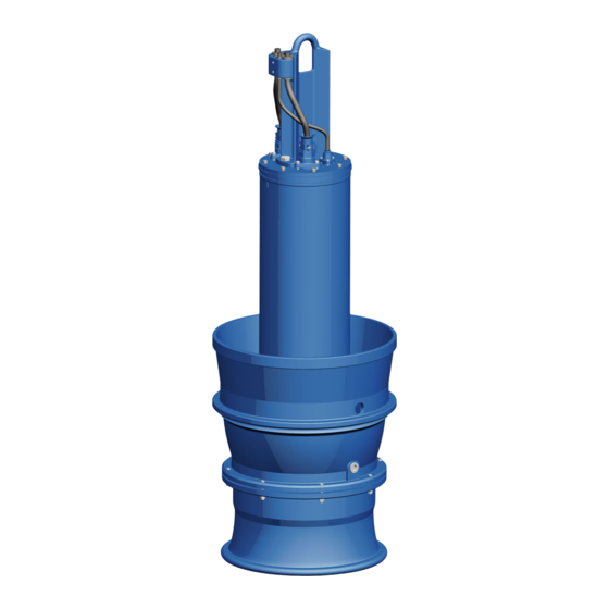
Submersible pump in discharge tube
Hide thumbs
Also See for Amacan P 700-470:
- Installation & operating manual (20 pages) ,
- Installation & operating manual (154 pages)

Related Manuals for KSB Amacan P 700-470


Summary of Contents for KSB Amacan P 700-470
- Page 1 Submersible Pump in Discharge Tube Amacan P 50 Hz Amacan P 700 - 470 Amacan P 800/900 - 540 Amacan P 1000 - 700 Amacan P 1200 - 870 Amacan P 1500/1600 - 1060 Installation/Operating Manual Mat. No.: 01137299...
- Page 2 All rights reserved. The contents provided herein must neither be distributed, copied, reproduced, edited or processed for any other purpose, nor otherwise transmitted, published or made available to a third party without the manufacturer's express written consent. Subject to technical modification without prior notice. © KSB SE & Co. KGaA, Frankenthal 03/09/2018...
-
Page 3: Table Of Contents
Contents Contents General.............................. 7 Principles ................................ 7 Installation of partly completed machinery.................... 7 Target group.............................. 7 Other applicable documents.......................... 7 Symbols ................................ 7 Safety .............................. 8 Key to safety symbols/markings........................ 8 General................................ 8 Intended use .............................. 9 Personnel qualification and training....................... 9 Consequences and risks caused by non-compliance with this manual ............ 9 Safety awareness .............................. 9 Safety information for the operator/user ....................... 9 Safety information for maintenance, inspection and installation .............. 10... - Page 4 Contents Commissioning/Start-up/Shutdown.................... 43 Commissioning/Start-up .......................... 43 6.1.1 Prerequisites for commissioning/start-up .................. 43 6.1.2 Start-up............................... 44 Operating limits.............................. 44 6.2.1 Operation on the power supply mains..................... 44 6.2.2 Frequency of starts.......................... 45 6.2.3 Operation on a frequency inverter.................... 45 6.2.4 Fluid handled ............................. 45 Shutdown/storage/preservation ........................ 47 6.3.1 Shutdown ............................ 47 6.3.2 Measures to be taken for shutdown .................... 47 Returning to service ............................ 48...
- Page 5 Contents Wiring diagrams ............................ 107 9.6.1 Installation type BU ......................... 107 9.6.2 Installation type BG ......................... 110 9.6.3 Installation type CU ......................... 112 9.6.4 Installation type CG ......................... 115 9.6.5 Installation type DU ......................... 118 9.6.6 Installation type DG ......................... 121 9.6.7 Dimensions of the flow-straightening vane................... 124 EU Declaration of Conformity ......................
- Page 6 Glossary Glossary Certificate of decontamination A certificate of decontamination is enclosed by the customer when returning the product to the manufacturer to certify that the product has been properly drained to eliminate any environmental and health hazards arising from components in contact with the fluid handled.
-
Page 7: General
In the event of damage, immediately contact your nearest KSB Service centre to maintain the right to claim under warranty. 1.2 Installation of partly completed machinery To install partly completed machinery supplied by KSB refer to the sub-sections under Servicing/Maintenance. -
Page 8: Safety
2 Safety 2 Safety All the information contained in this section refers to hazardous situations. DANGER In addition to the present general safety information the action-related safety information given in the other sections must be observed. 2.1 Key to safety symbols/markings Table 3: Definition of safety symbols/markings Symbol Description... -
Page 9: Intended Use
2 Safety 2.3 Intended use ▪ The pump (set) must only be operated in the fields of application and within the use limits specified in the other applicable documents. ▪ Only operate pumps/pump sets which are in perfect technical condition. ▪... -
Page 10: Safety Information For Maintenance, Inspection And Installation
2 Safety ▪ Contain leakages (e.g. at the shaft seal) of hazardous fluids handled (e.g. explosive, toxic, hot) so as to avoid any danger to persons and the environment. Adhere to all relevant laws. ▪ Eliminate all electrical hazards. (In this respect refer to the applicable national safety regulations and/or regulations issued by the local energy supply companies.) ▪... -
Page 11: Repair
2 Safety 2.10.1 Repair Special regulations apply to repair work on explosion-proof pumps. Modifications or alterations of the pump set can affect explosion protection and are only permitted after consultation with the manufacturer. Repair work at the flameproof joints must only be performed in accordance with the manufacturer's instructions. -
Page 12: Transport/Temporary Storage/Disposal
1. On transfer of goods, check each packaging unit for damage. 2. In the event of in-transit damage, assess the exact damage, document it and notify KSB or the supplying dealer and the insurer about the damage in writing immediately. - Page 13 3 Transport/Temporary Storage/Disposal WARNING Placing the pump set down on unsecured and uneven surfaces Personal injury and damage to property! ▷ Always place down the pump set on a solid and level surface with the pump set in a vertical position and the motor on top. ▷...
-
Page 14: Transporting The Pump Set
3 Transport/Temporary Storage/Disposal Pulling the pump set upright with one Pulling the pump set upright with two crane cranes ü Suitable lifting equipment has been selected (e.g. crane). 1. a) For one piece of lifting equipment: Attach the eyehook to the bail of the pump set. -
Page 15: Transport Lock
3 Transport/Temporary Storage/Disposal WARNING Improper handling when placing the pump set in a vertical/horizontal position Personal injury and damage to property! ▷ Use one or two pieces of lifting equipment, depending on the pump size. ▷ Use appropriate means to secure the pump set against tilting, tipping over or rolling off. -
Page 16: Return To Supplier
4. Always complete and enclose a certificate of decontamination when returning the pump. Indicate any safety measures and decontamination measures taken. (ð Section 11, Page 127) NOTE If required, a blank certificate of decontamination can be downloaded from the following web site: www.ksb.com/certificate_of_decontamination Amacan P 16 of 132... -
Page 17: Disposal
3 Transport/Temporary Storage/Disposal 3.5 Disposal WARNING Fluids handled, consumables and supplies which are hot and/or pose a health hazard Hazard to persons and the environment! ▷ Collect and properly dispose of flushing fluid and any fluid residues. ▷ Wear safety clothing and a protective mask if required. ▷... -
Page 18: Description Of The Pump (Set)
II 2G Ex db h IIB T3 Gb Material variant Grey cast iron, standard material variant Grey cast iron with Zn anodes, shaft made of 1.4057 stainless steel 4.3 Name plate KSB SE & Co. KGaA KSB SE & Co. KGaA Johann-Klein-Straße 9 Johann-Klein-Straße 9 67227 Frankenthal... -
Page 19: Design Details
4 Description of the Pump (Set) Power factor at rated operating point Rated frequency Duty cycle Starting current ratio ATEX marking for the submersible motor ATEX marking for the pump set 4.4 Design details Design ▪ Fully floodable submersible pump in discharge tube (submersible motor pump) ▪... -
Page 20: Configuration And Function
4 Description of the Pump (Set) BG discharge tube CG discharge tube DG discharge tube Overflow design for installation in Design with underfloor discharge Design with above-floor discharge covered intake chamber with low for installation in covered intake nozzle for installation in covered intake suction-side water levels chamber with low suction-side chamber with low suction-side water... -
Page 21: Scope Of Supply
▪ Flow-straightening vane to prevent floor vortices NOTE A separate name plate is included in KSB's scope of supply. This name plate must be attached in a clearly visible position outside the place of installation, e.g. at the control panel, pipeline or mounting bracket. -
Page 22: Installation At Site
Back-up name plate KSB’s scope of supply includes a separate name plate attached to the end of the pump cable which indicates the pump and motor data. -
Page 23: Checking The Direction Of Rotation
5 Installation at Site 903.03 903.01 411.01 Fig. 5: Checking the lubricant level Table 7: Key to the symbols and codes Symbol Description Always apply a liquid sealant (e.g. Hylomar SQ32M) to sealing surfaces marked with this symbol. 1. Place the pump set down in a horizontal position and make sure it cannot roll off. - Page 24 5 Installation at Site WARNING Improper handling when placing the pump set in a vertical/horizontal position Personal injury and damage to property! ▷ Use one or two pieces of lifting equipment, depending on the pump size. ▷ Use appropriate means to secure the pump set against tilting, tipping over or rolling off.
-
Page 25: Lowering The Pump Set Into The Discharge Tube
5 Installation at Site WARNING Unintentional starting of the pump set Risk of injury by moving components and shock currents! ▷ Ensure that the pump set cannot be started unintentionally. ▷ Always make sure the electrical connections are disconnected before carrying out work on the pump set. -
Page 26: Information For Correct Installation
5 Installation at Site 5.3.1 Information for correct installation The flow-straightening vane is indispensable for the inlet conditions of the pump set. It prevents the development of a submerged vortex (floor vortex) which could cause a drop in performance, for example. To provide optimum inlet conditions, observe the following information: Observe the structural requirements! Install the flow-straightening vane concentrically below the discharge tube, see... -
Page 27: Installation With A Support Rope
5 Installation at Site Refer to and comply with the general arrangement drawing/outline drawing when installing the pump set. 1. If not already fitted, insert the supplied O-ring 412.05 into pump bowl 112. 412.05 2. Attach the crane hook to the bail of the pump set. 3. - Page 28 5 Installation at Site WARNING Pump set drops during the installation or removal process Personal injury and damage to property! ▷ Never use the turnbuckle , shackle or discharge tube cover to lift the pump set. ▷ Always use lifting lug 59-47. NOTE Prior to fitting the turnbuckle, check that the corresponding split pin has not been cracked and/or chipped.
- Page 29 5 Installation at Site 8. Attach the first lifting lug of the support rope (5) to the lifting rope (1) to securely position the pump set above the discharge tube. 9. Unclip the hook of the lifting equipment from the lifting lug of the support rope and run the lifting equipment to a higher level.
-
Page 30: Installation With A Support Rope And Support Spacer
5 Installation at Site Fig. 15: Lowering the pump set 18. Finally, attach the support rope with shackle and turnbuckle to a suspension loop (provided in the discharge tube or structure). Secure the turnbuckle with a split pin. After inserting the split pin, bend over its two legs. 19. - Page 31 5 Installation at Site CAUTION Incorrect installation Damage to the pump set! ▷ Verify that the pump set is correctly seated in the discharge tube. WARNING Pump set drops during the installation or removal process Personal injury and damage to property! ▷...
- Page 32 5 Installation at Site 6. Securely cover the discharge tube except for a gap which allows work to continue. 7. Attach the first lifting lug of the support rope (5) to the lifting rope (1) to securely position the pump set above the discharge tube. 8.
- Page 33 5 Installation at Site 733.05 719.05 59-7 81-51 (185, 81-39) 59-24 733.05 719.05 Fig. 21: Support rope with support, dimensions in mm *) depending on the cable cross-section, **) for 1 rope or 3 ropes = 30 mm 19. Clamp support 59-7 with guide plate 55-1 to the support rope (f). 20.
- Page 34 5 Installation at Site Fig. 22: Lowering the pump set 24. Progressively lower the pump set into the discharge tube. Secure the cables with cable clamps. 25. Finally, attach the support rope with shackle and turnbuckle to a suspension loop (provided in the discharge tube or structure). Secure the turnbuckle with a split pin.
-
Page 35: Electrical System
5 Installation at Site 5.4 Electrical system 5.4.1 Information for planning the control system For the electrical connection of the pump set observe the wiring diagrams contained in the Annex. (ð Section 9.3, Page 96) The pump set is supplied with power cables; it is wired for DOL starting. Star-delta starting is also possible, except for size Amacan P 1600 - 1060. - Page 36 Suitable analysing devices must be selected. To monitor the leakage sensor inside the motor using a special relay available from KSB is recommended. Amacan P 36 of 132...
- Page 37 The pump set features sensors designed to prevent hazards and damage to the pump set. Measuring transducers are required for analysing the sensor signals supplied. Suitable devices for 230 V AC can be supplied by KSB. NOTE Reliable and safe operation of the pump within the scope of our warranty is only possible if the sensor signals are properly analysed as stipulated in this manual.
- Page 38 5 Installation at Site Position Sensor Standard Optional Leakage inside the motor (connection and winding ✘ space) Bearing temperature (upper bearing) ✘ Bearing temperature (lower bearings) ✘ Mechanical seal leakage ✘ Vibration sensor ✘ Motor temperature (PTC) ✘ Motor temperature (Pt100) ✘...
- Page 39 5 Installation at Site 5.4.1.5.2 Leakage inside the motor DANGER Incorrect monitoring of leakage electrode Explosion hazard! Danger of death from electric shock! ▷ Voltages must be < 30 V AC and tripping currents < 0.5 mA. Wiring of the electrode relay Wiring of the electrode relay (pump Position of the electrodes in the (standard) sets with vibration sensor only)
- Page 40 5 Installation at Site As an option, the upper bearing can also be equipped with a temperature sensor (core identification 16 and 17). Its connection and settings are identical with the above. Check in the data sheet whether the pump set is equipped with temperature monitoring of the upper bearing.
-
Page 41: Electrical Connection
5 Installation at Site 5.4.2 Electrical connection DANGER Electrical connection work by unqualified personnel Risk of fatal injury due to electric shock! ▷ Always have the electrical connections installed by a trained and qualified electrician. ▷ Observe regulations IEC 60364 and, for explosion-proof models, EN 60079. WARNING Incorrect connection to the mains Damage to the mains network, short circuit! - Page 42 5 Installation at Site DANGER Connection of damaged power cables Danger of death from electric shock! ▷ Check the power cables for damage before connecting them. ▷ Never connect damaged power cables. ▷ Replace damaged power cables. CAUTION Flow-induced motion Damage to the power cable! ▷...
-
Page 43: Commissioning/Start-Up/Shutdown
6 Commissioning/Start-up/Shutdown 6 Commissioning/Start-up/Shutdown 6.1 Commissioning/Start-up 6.1.1 Prerequisites for commissioning/start-up DANGER Persons in the tank during pump operation Electric shock! Risk of injury! Danger of death from drowning! ▷ Never start up the pump set without special protective equipment when there are persons in the tank. -
Page 44: Start-Up
6 Commissioning/Start-up/Shutdown 6.1.2 Start-up DANGER Persons in the tank during pump operation Electric shock! Risk of injury! Danger of death from drowning! ▷ Never start up the pump set without special protective equipment when there are persons in the tank. ▷... -
Page 45: Frequency Of Starts
6 Commissioning/Start-up/Shutdown The mains voltage and mains frequency may fluctuate around the rated values as defined for zone B to IEC 60034-1. The voltage difference between the individual phases must not exceed 1 %. 6.2.2 Frequency of starts CAUTION Excessive frequency of starts Risk of damage to the motor! ▷... - Page 46 6 Commissioning/Start-up/Shutdown CAUTION Impermissibly high density of the fluid handled Motor overload! ▷ Observe the information about fluid density in the data sheet. ▷ Make sure the motor has sufficient power reserves. 6.2.4.3 Minimum level of fluid handled DANGER Pump set running dry Explosion hazard! ▷...
-
Page 47: Shutdown/Storage/Preservation
6 Commissioning/Start-up/Shutdown 6.3 Shutdown/storage/preservation 6.3.1 Shutdown CAUTION Uncontrolled backflow of the fluid from the riser Damage to the pump set! ▷ Prevent any uncontrolled backflow of the fluid handled with suitable means. ▷ Control the fluid backflow, e.g. by throttling the gate valve in the discharge line. -
Page 48: Returning To Service
6 Commissioning/Start-up/Shutdown The pump (set) is removed from the pipe and stored ü All safety regulations are observed. (ð Section 7.1, Page 49) 1. Clean the pump set. 2. Spray-coat the inside wall of the pump casing and, in particular, the impeller clearance areas with a preservative. 6.4 Returning to service For returning the pump set to service, observe the items on commissioning/start-up. -
Page 49: Servicing/Maintenance
7 Servicing/Maintenance 7 Servicing/Maintenance 7.1 Safety regulations The operator ensures that maintenance, inspection and installation is performed by authorised, qualified specialist personnel who are thoroughly familiar with the manual. DANGER Sparks produced during servicing work Explosion hazard! ▷ Observe the safety regulations in force at the place of installation! ▷... - Page 50 NOTE All maintenance work, service work and installation work can be carried out by KSB Service or authorised workshops. For contact details please refer to the enclosed "Addresses" booklet or visit "www.ksb.com/contact" on the Internet.
-
Page 51: Maintenance/Inspection
7 Servicing/Maintenance 7.2 Maintenance/inspection KSB recommends the following regular maintenance schedule: Table 9: Overview of maintenance work Maintenance interval Servicing/maintenance work For details see ... Every 4000 hours, at least once a Measuring the insulation resistance (ð Section 7.2.1.1, Page 51) year Every 8000 hours, at least every Checking the cable bundle (ð Section 7.3.3, Page 54) - Page 52 7 Servicing/Maintenance The tests described below measure the resistance at the core ends of the control cable. The actual sensor function is not tested. Temperature sensors in the Table 10: Resistance measurement motor winding Measurement between terminals ... Resistance [Ω] 10 and 11 200 - 1000 31 and 32 100 - 120...
-
Page 53: Removing The Pump Set
7 Servicing/Maintenance 7.3 Removing the pump set 7.3.1 Removing the pump set DANGER Insufficient preparation of work on the pump (set) Risk of injury! ▷ Properly shut down the pump set. ▷ Close the shut-off elements in the suction line and discharge line. ▷... -
Page 54: Drainage/Cleaning
7 Servicing/Maintenance 5. Attach the lifting chain or lifting rope with the shackle to the first lifting lug (together with the crane hook). 6. Unclip the crane hook and attach it to the second lifting lug. 7. Pull the pump set up until it reaches the third lifting lug. Free the lifting chain or lifting rope from the first lifting lug and attach it to the third lifting lug. -
Page 55: Checking The Earth Conductor
7 Servicing/Maintenance Longer sections of combined cables must be dismantled: 1. Remove the cables from the cable clamps. 2. Remove the spacer. 3. Roll up the cables and place them next to the pump set. 4. Undo the shackle to separate the support rope from the pump set. 7.3.4 Checking the earth conductor 1. -
Page 56: Lubrication And Lubricant Change
7 Servicing/Maintenance Table 15: Key to the symbols and codes Symbol Description Always apply a liquid sealant (e.g. Hylomar SQ32M) to sealing surfaces marked with this symbol. ü A suitable container for the leakage is on hand. ü The pump is positioned horizontally on a level surface and is protected against rolling off. - Page 57 7 Servicing/Maintenance WARNING Lubricant contaminating fluid handled Hazard to persons and the environment! ▷ Using machine oil is only permitted if the oil is disposed of properly. 7.4.1.3 Lubricant quantity Table 17: Lubricant quantity [l] depending on size Size Lubricant quantity 700 - 470 800 - 540 900 - 540...
- Page 58 7 Servicing/Maintenance 7.4.1.4.1 Draining the lubricant 903.01 411.01 903.03 Fig. 29: Draining the lubricant 1. Place the pump set down in a horizontal position and make sure it cannot roll off. 2. Remove screw plug 903.03. 3. Remove screw plug 903.01 and joint ring 411.01. 4.
-
Page 59: Lubricating The Rolling Element Bearings
7 Servicing/Maintenance 6. Remove the tube. Fit screw plug 903.01 together with a new joint ring 411.01. Apply a liquid sealant. 7. Insert and tighten screw plug 903.03. 7.4.2 Lubricating the rolling element bearings The pump set is equipped with grease-lubricated, maintenance-free rolling element bearings. -
Page 60: Dismantling The Pump Set
▷ Never suspend the pump set by its power cable. ▷ Never use the lifting ropes included in KSB's scope of supply for lifting loads other than the KSB product supplied. ▷ Securely attach the lifting ropes to the pump and crane. -
Page 61: Preparing The Pump Set
7 Servicing/Maintenance WARNING Pump set tilting or rolling off Risk of personal injury! ▷ Make sure the pump set is secured against tilting during the entire dismantling process. ▷ For dismantling the pump set in a horizontal position, secure it against rolling off. -
Page 62: Removing The Impeller
7 Servicing/Maintenance 7.5.4 Removing the impeller 914.07 940.02 Fig. 32: Removing the impeller ü The pump has been placed on wooden supports in a horizontal position and is protected against rolling off. ü The lubricant and leakage have been drained. 1. Undo socket head cap screw 914.07 and impeller nut 922. 2. - Page 63 7 Servicing/Maintenance 7.5.5.2 Impeller-end mechanical seal for pump sizes 1500-... to 1600-... 914.55 433.02 Fig. 34: Impeller-end mechanical seal ü The pump has been securely placed in a horizontal position on wooden supports. ü The impeller has been removed. 1. Undo the grub screws (a) of mechanical seal 433.02. Pull the rotating assembly of the mechanical seal off the shaft.
-
Page 64: Dismantling The Motor Section
7 Servicing/Maintenance 4. Place motor unit 80-1 including rotor 818 with bearing and bearing housing 350 on a wooden support and protect it against rolling off. (ð Section 3.2.2, Page 12) 5. Remove circlip 932.03 and disc 550.03. 6. Carefully pull mechanical seal 433.01 and the mating ring of the mechanical seal off the shaft. - Page 65 7 Servicing/Maintenance When dismantling the motor section and the power cable make sure that the cores/ terminals are clearly marked for future reassembly. 7.5.6.1 Removing the motor housing cover 835/ 81-2 903.51 914.01 Fig. 37: Removing the motor housing cover ü Suitable lifting equipment is on hand. ü...
-
Page 66: Reassembling The Pump Set
7 Servicing/Maintenance 7.5.6.2 Removing the cable gland and connection cable 68-3.02 (82-11) A - A 81-18.03 914.05 834.01 901.20 932.20 834.02 81-29.03 914.04 Fig. 38: Removing the connection cable and cable gland Removing the power cable ü The motor housing cover has been removed, placed down and protected against rolling off. - Page 67 Before reassembling the motor section, check that all joints relevant to explosion protection (flamepaths) are undamaged. Any components with damaged flamepaths must be replaced. Only use original spare parts made by KSB for explosion-proof pumps. Observe the flamepath positions specified in the Annex.
-
Page 68: Installing The Replacement Cable Gland
7 Servicing/Maintenance 7.6.2 Installing the replacement cable gland 834.01 914.05 834.02 914.04 412.08 412.07 Fig. 39: Installing the cable gland Table 21: Key to the symbols and codes Symbol Description Always secure screwed connections marked with this symbol with Loctite 243. ü The motor housing cover has been removed, set down and protected against Connecting the power cable rolling off. -
Page 69: Fitting The Motor Housing Cover
7 Servicing/Maintenance 7.6.3 Fitting the motor housing cover 7.6.3.1 Fitting the motor housing cover — pump sizes 700 to 1500 DANGER Electrical connection work by unqualified personnel Risk of fatal injury due to electric shock! ▷ Always have the electrical connections installed by a trained and qualified electrician. - Page 70 7 Servicing/Maintenance 7.6.3.2 Fitting the motor housing cover — pump size 1600-... DANGER Electrical connection work by unqualified personnel Risk of fatal injury due to electric shock! ▷ Always have the electrical connections installed by a trained and qualified electrician. ▷...
-
Page 71: Installing The Mechanical Seal
7 Servicing/Maintenance 7. Cover the jacking threads with caps 903.51. 8. Perform a leak test on the motor. (ð Section 7.6.7.2, Page 78) 7.6.4 Installing the mechanical seal Observe the following to ensure trouble-free operation of the mechanical seal: ▪ Only remove the protective wrapping of the contact faces immediately before assembly takes place. - Page 72 7 Servicing/Maintenance 5. Attach the crane hook to the bail and pull upright motor unit 80-1 including rotor 818 with bearing and bearing housing 350. (ð Section 3.2.2, Page 12) 6. Place the pump set on the pump casing and bellmouth. Fasten it with hexagon socket head cap screws 914.02.
- Page 73 7 Servicing/Maintenance 6. Attach the crane hook to bail 571 and pull upright motor unit 80-1 including rotor 818 with bearing and bearing housing 350. (ð Section 3.2.2, Page 12) 7. Place the pump set on the pump bowl and bellmouth. Fasten it with hexagon socket head cap screws 914.02.
- Page 74 7 Servicing/Maintenance 7.6.4.4 Impeller-end mechanical seal — pump sizes 1500-... to 1600-... 914.55 433.02 Fig. 45: Impeller-end mechanical seal Table 26: Key to the symbols and codes Symbol Description Always secure screwed connections marked with this symbol with Loctite 243. ü The pump bowl has been fastened to the motor. ü...
-
Page 75: Fitting The Impeller
7 Servicing/Maintenance 7.6.5 Fitting the impeller 914.07 940.02 Fig. 46: Fitting the impeller ü The pump has been placed on a wooden support in a horizontal position and is protected against rolling off. ü The impeller-end mechanical seal 433.02 has been installed. 1. -
Page 76: Fitting The Bellmouth
7 Servicing/Maintenance 7.6.6 Fitting the bellmouth 7.6.6.1 Fitting the bellmouth for pressure class A 903.05 920.01 550.01 Fig. 47: Impeller of pressure class A ü Bellmouth 138 has been positioned on wooden supports on a level and solid surface. ü Suitable lifting equipment is provided. ü... -
Page 77: Leak Testing
7 Servicing/Maintenance 902.01 920.01 550.01 901.01 903.06 914.07 Fig. 48: Impeller of pressure class B ü Bellmouth 138 has been positioned on wooden supports on a level and solid surface. ü Suitable lifting equipment is provided. ü The pump set has been completely pre-assembled. ü... - Page 78 7 Servicing/Maintenance Observe the following values for leak testing: ▪ Test medium: compressed air ▪ Test pressure: 1 bar maximum ▪ Test duration: 5 minutes 1,0 bar Fig. 49: Screwing in the testing device 1. Unscrew and remove the screw plug and joint ring of the lubricant reservoir. 2.
-
Page 79: Checking The Electrical Connection And Motor
7 Servicing/Maintenance Table 29: Key to the symbols and codes Symbol Description Always secure screwed connections marked with this symbol with Loctite 243. Always apply a liquid sealant (e.g. Hylomar SQ32M) to sealing surfaces marked with this symbol. 1. Undo and remove screw plug 903.31 and joint ring 411.31. 2. -
Page 80: Spare Parts Stock
7 Servicing/Maintenance Steel grade A2, A4 A2, A4 1.4410 1.4462 Property class ≥ 530 N/mm ≥ 450 N/mm p0.2 p0,2 Thread 3904 4338 1281 1423 2745 3050 3233 3592 2745 3050 5880 6534 1929 2144 4135 4594 4870 5411 4135 4594 NOTE If using an adjustable torque wrench or screwdriver, adjust it to a value within the... - Page 81 7 Servicing/Maintenance Part No. Description Number of pumps (including stand-by pumps) 10 and more 99-9 Set of sealing elements, 100 % motor 99-9 Set of sealing elements, 100 % hydraulic system Amacan P 81 of 132...
-
Page 82: Trouble-Shooting
- No voltage Check electrical connections. Contact the energy supplier. ✘ - Motor winding or electric cable are defective. Replace with original KSB cable or contact KSB. ✘ ✘ Worn or defective rolling element bearings Contact KSB. ✘ - The thermistor tripping unit with manual reset... - Page 83 8 Trouble-shooting A B C D E Possible causes Remedy ✘ - Mechanical seal monitor has tripped. Have cause determined and eliminated by qualified and trained personnel. ✘ - Bearing temperature monitor has tripped. Have cause determined and eliminated by qualified and trained personnel.
-
Page 84: Related Documents
9 Related Documents 9 Related Documents 9.1 General assembly drawing 914.25 82-11 412.01 81-18.03 901.20 932.37 932.20 80-1 914.03 914.02 412.02 412.05 421.02 500.02 932.02 433.01 412.03 550.03 932.03 904.01 433.02 940.02 550.44 932.44 Q NB 50 Fig. 51: General assembly drawing Amacan P 84 of 132... - Page 85 9 Related Documents Table 33: Detailed views of the general assembly drawing Connection of cable Motor sizes: gland 47 6 ... 205 6 81-97.01 and fastening 30 8 ... 160 8 81-97.02 60 10 ... 120 10 82-11 901.26 914.01 914.05 914.04 834.01 834.02...
- Page 86 9 Related Documents Table 34: Detailed views of the general assembly drawing Bearing, motor end Motor sizes: 47 6 ... 205 6 30 8 ... 290 8 60 10 ... 250 10 130 12 ... 190 12 932.29 500.29 421.01 500.01 932.01 932.13 500.04...
- Page 87 9 Related Documents Table 35: Detailed views of the general assembly drawing Bearing, pump end Motor sizes: 47 6 ... 205 6 30 8 ... 290 8 60 10 ... 470 10 130 12 ... 410 12 210 14 ... 340 14 932.02 500.02 421.02...
- Page 88 9 Related Documents Table 36: Detailed views of the general assembly drawing Sensors/terminals, Motor sizes: bearing bracket 47 6 ... 205 6 900.06 69-14.01 932.06 30 8 ... 290 8 99-4.01** 81-2.01 60 10 ... 470 10 130 12 ... 410 12 99-17.01 210 14 ...
- Page 89 9 Related Documents Table 37: Detailed views of the general assembly drawing Bearing bracket Motor sizes: fastening 47 6 ... 205 6 30 8 ... 160 8 932.37 60 10 ... 120 10 Motor sizes: 205 8 ... 290 8 155 10 ... 470 10 130 12 ...
- Page 90 9 Related Documents Table 38: Detailed views of the general assembly drawing Screwed connection bellmouth / pump bowl 902.01 920.01 903.05 550.01 Impeller fasteners 914.07 Float switch 81-45 411.26 Lubricant and leakage chamber 903.01 903.03 903.02 411.01 411.02 Amacan P 90 of 132...
- Page 91 9 Related Documents Table 39: Detailed views of the general assembly drawing Labels/plates 970.01 970.02 970.22 970.05 970.04 970.03 Table 40: Key to the symbols and codes Symbol Description Always secure screwed connections marked with this symbol with Loctite 243. Always apply a liquid sealing agent (e.g. Hylomar SQ32M) to sealing surfaces marked with this symbol.
- Page 92 9 Related Documents Part No. Description Part No. Description 520.01/.02 Sleeve 902.01 Stud 550.01/.03/.05/.23/.25/.44/. Disc 903.01/.02/.03/.05/.31/.51 Screw plug 561.01 Grooved pin 904.01 Grub screw Bail 914.01/.02/.03/.04/.05/.07/. Hexagon socket head cap 19/.25/.48/.51/.52 screw 68-3 Cover plate 920.01/.23/.24/.25 69-6 Temperature sensor Impeller nut 69-8 Sensor 932.01/.02/.03/.05/.06/.12/.
-
Page 93: Special Features
9 Related Documents 9.1.1 Special features Table 42: Special features Description Detailed view Terminal block for 900.30 R35 motors *914.50 *826 310 10 ... 470 10 *68-3.03 250 12 ... 410 12 210 14 ... 340 14 * Explosion-proof variants only Hydraulic system Hydraulic system A Hydraulic system B... -
Page 94: Cable Bundle
9 Related Documents Part No. Description Part No. Description Impeller 82-5 Adapter 412.06 O-ring 914.02/.06/.50 Hexagon socket head cap screw 9.2 Cable bundle 59-8 59-8 59-8 59-17.02 59-17.02 59-17.02 (59-47) (59-47) (59-47) 733.05 733.05 719.05 733.05 719.05 719.05 59-24 59-24 59-7 (59-47) 59-24... - Page 95 9 Related Documents A - A 733.05 59-24 719.05 Fig. 53: Cross-section A - A, position of power cable, control cable and support rope Power cable Control cable Table 45: List of components of the cable bundle Part No. Description Part No. Description 59-7 Support...
-
Page 96: Wiring Diagrams
9 Related Documents 9.3 Wiring diagrams 9.3.1 Wiring diagram for the power cable 700-470…1500-1060 Fig. 54: Wiring diagram for the power cable 700-470…1500-1060 * Shielded cable optional Up to 3 parallel cable pairs possible Amacan P 96 of 132... -
Page 97: Wiring Diagram For The Power Cable 1600-1060
9 Related Documents 9.3.2 Wiring diagram for the power cable 1600-1060 Fig. 55: Wiring diagram for the power cable 1600-1060 * Shielded cable optional Up to 8 parallel cable pairs possible Amacan P 97 of 132... -
Page 98: Wiring Diagrams For The Sensors
9 Related Documents 9.3.3 Wiring diagrams for the sensors Standard pump sets Fig. 56: Wiring diagram for sensors of standard pump sets Shielded cables optional Ⓐ Motor temperature (PTC) Ⓑ Mechanical seal leakage Bearing temperature (lower bearings) Ⓒ Ⓓ Bearing temperature (upper bearing, optional) Ⓕ... - Page 99 9 Related Documents Pump sets with additional monitoring by vibration sensor Fig. 57: Wiring diagram for sensors of pump sets with additional monitoring by vibration sensor Ⓐ Motor temperature (PTC) Ⓑ Mechanical seal leakage Bearing temperature (lower bearings) Ⓒ Bearing temperature (upper bearing, optional) Ⓓ...
- Page 100 9 Related Documents Pump sets with additional Pt100 motor temperature monitoring Fig. 58: Wiring diagram for sensors of pump sets with additional motor temperature monitoring (Pt100) Motor temperature (PTC) Ⓐ Mechanical seal leakage Ⓑ Ⓒ Bearing temperature (lower bearings) Ⓓ Bearing temperature (upper bearing, optional) Leakage inside the motor Ⓕ...
- Page 101 9 Related Documents Pump sets with additional Pt100 motor temperature monitoring and vibration sensor Fig. 59: Wiring diagram for sensors of pump sets with additional Pt100 motor temperature monitoring and vibration sensor Ⓐ Motor temperature (PTC) Ⓑ Mechanical seal leakage Bearing temperature (lower bearings) Ⓒ...
-
Page 102: Flamepaths On Explosion-Proof Motors
9 Related Documents 9.4 Flamepaths on explosion-proof motors Fig. 60: Flamepaths for explosion-proof motors Amacan P 102 of 132... -
Page 103: Dimensions
9 Related Documents 9.5 Dimensions Fig. 61: Outline drawing of the pump set Table 46: Dimensions of the pump set Size Motor size Number [kg] of poles A 700 - 470 2190 2150 430 1500 735 A 700 - 470 2190 2150 430 1500 735 A 700 - 470 2390 2350 430 1700 735 1015... - Page 104 9 Related Documents Size Motor size Number [kg] of poles B 800 - 540 2445 2405 550 1755 945 1315 A 900 - 540 2615 2575 570 1925 1045 1555 A 900 - 540 2615 2575 570 1925 1045 1655 B 900 - 540 2615 2575 570 1925 1045 1580...
- Page 105 9 Related Documents Size Motor size Number [kg] of poles A 1600-1060 1540 1350 1300 760 4085 3995 1260 3375 1800 100 7050 A 1600-1060 1540 1350 1300 760 4085 3995 1260 3375 1800 100 7370 45° Fig. 62: Outline drawing of the discharge tube Suction umbrella;...
- Page 106 9 Related Documents Size Motor size Number of poles B 1000 - 700 1016 1015 1600 B 1000 - 700 1016 1015 1600 B 1000 - 700 1016 1015 1600 A 1200 - 870 1220 1070 1220 2000 1000 A 1200 - 870 1220 1070 1220...
-
Page 107: Wiring Diagrams
9 Related Documents 9.6 Wiring diagrams 9.6.1 Installation type BU Foundation recesses A - A B - B Detailed view X: Support plate of the discharge tube Drawing: without pump 0 - 10° = 1 m/s max. Detailed view Y: seating ring ①: Minimum water level (values see diagram on the following pages) ②: Flow-straightening vane (ð Section 9.6.7, Page 124) - Page 108 9 Related Documents Table 49: Dimensions [mm] Size min. 4 min. Without suction With suction umbrella umbrella 700 - 470 1050 2300 800 - 540 1300 1000 2350 900 - 540 1300 1050 1120 2500 1000 - 700 1700 1150 1220 3050 1200 - 870 1100...
- Page 109 9 Related Documents Minimum water level diagrams Open intake chamber (design without suction umbrella Ø d t 1 [mm] 3 - Amacan P 700 - 470 4000 4 - Amacan P 800/900 - 540 5 - Amacan P 1000 - 700 3000 6 - Amacan P 1200 - 870 2500...
-
Page 110: Installation Type Bg
9 Related Documents 9.6.2 Installation type BG Foundation recesses A - A B - B Detailed view X: Support plate of the discharge tube Drawing: without pump 0 - 90° = 1 m/s max. ①: Minimum water level (values see diagrams on the following pages) ②: Flow-straightening vane (ð Section 9.6.7, Page 124) Detailed view Y: ③: Approach flow... - Page 111 9 Related Documents Size min. 4 min. 1000 - 700 2300 1150 1220 3050 1200 - 870 1000 2800 1360 1420 1160 3750 1050 1500 - 1060 1460 3500 1680 1750 1480 3900 1320 1600 - 1060 1230 3500 1780 1850 1580 4350...
-
Page 112: Installation Type Cu
9 Related Documents 9.6.3 Installation type CU Foundation recesses Section A - A: B - B Detailed view X: Support plate of the discharge tube Drawing: without pump 0 - 10° = 1 m/s max. Detailed view Y: ①: Vent line seating ring ②: Minimum water level (values see diagram on the following pages) ③: Flow-straightening vane (ð Section 9.6.7, Page 124) - Page 113 9 Related Documents Table 53: Dimensions [mm] Size min. 4 min. 5 min. Without With suction suction umbrella umbrella 700 - 470 1100 1050 1170 1260 1060 2400 800 - 540 1250 1300 1270 1375 1075 1175 2450 900 - 540 1250 1300 1380...
- Page 114 9 Related Documents Minimum water level diagrams Open intake chamber (design without suction umbrella Ø d t 1 [mm] 3 - Amacan P 700 - 470 4000 4 - Amacan P 800/900 - 540 5 - Amacan P 1000 - 700 3000 6 - Amacan P 1200 - 870 2500...
-
Page 115: Installation Type Cg
9 Related Documents 9.6.4 Installation type CG Foundation recesses Section A - A: B - B Detailed view X: Support plate of the discharge tube Drawing: without pump 0 - 90° = 1 m/s max. ①: Vent line Detailed view Y: ②: Minimum water level (values see diagram on the following pages) seating ring ③: Flow-straightening vane (ð Section 9.6.7, Page 124) - Page 116 9 Related Documents Table 55: Dimensions [mm] Size min. 4 min. 5 min. 700 - 470 1500 1170 1260 1060 2400 800 - 540 1800 1270 1375 1075 1175 2450 900 - 540 1800 1380 1480 1180 1280 2650 1000 - 700 1150 2300 1520...
- Page 117 9 Related Documents Minimum water level diagram Covered intake chamber t 1 [mm] 3 - Amacan P 700 - 470 4000 4 - Amacan P 800/900 - 540 3000 5 - Amacan P 1000 - 700 2500 6 - Amacan P 1200 - 870 7 - Amacan P 1500/1600 - 1060 2000 1600...
-
Page 118: Installation Type Du
9 Related Documents 9.6.5 Installation type DU Foundation recesses Section A - A: B - B Detailed view X: Support plate of the discharge tube Drawing: without pump 0 - 10° = 1 m/s max. Detailed view Y: seating ring ①: Vent line ②: Minimum water level (values see diagram on the following pages) ③: Flow-straightening vane (ð Section 9.6.7, Page 124) - Page 119 9 Related Documents Table 57: Dimensions [mm] Size min. 4 min. Without With suction suction umbrella umbrella 700 - 470 1100 1050 1160 2400 800 - 540 1250 1300 1030 1260 1060 2450 900 - 540 1250 1300 1130 1360 1060 1160 2650 1000 - 700...
- Page 120 9 Related Documents Minimum water level diagrams Open intake chamber (design without suction umbrella Ø d t 1 [mm] 3 - Amacan P 700 - 470 4000 4 - Amacan P 800/900 - 540 5 - Amacan P 1000 - 700 3000 6 - Amacan P 1200 - 870 2500...
-
Page 121: Installation Type Dg
9 Related Documents 9.6.6 Installation type DG Foundation recesses Section A - A: B - B Detailed view X: Support plate of the discharge tube Drawing: without pump 0 - 90° = 1 m/s max. ①: Vent line Detailed view Y: ②: Minimum water level (values see diagram on the following pages) seating ring ③: Flow-straightening vane (ð Section 9.6.7, Page 124) - Page 122 9 Related Documents Size min. 4 min. 900 - 540 1800 1130 1360 1060 1160 2650 1000 - 700 1150 2300 1240 1500 1160 1260 3250 1200 - 870 1400 1000 2800 1440 1700 1360 1460 4000 1050 1500 - 1060 1048 1750 1460...
- Page 123 9 Related Documents Minimum water level diagram Covered intake chamber t 1 [mm] 3 - Amacan P 700 - 470 4000 4 - Amacan P 800/900 - 540 3000 5 - Amacan P 1000 - 700 2500 6 - Amacan P 1200 - 870 7 - Amacan P 1500/1600 - 1060 2000 1600...
-
Page 124: Dimensions Of The Flow-Straightening Vane
9 Related Documents 9.6.7 Dimensions of the flow-straightening vane Design of the intake chamber wall surfaces (to prevent vortex formation) The flow-straightening vane is indispensable for the inlet conditions of the pump set. It prevents the development of a submerged vortex (floor vortex) which could cause a drop in performance, for example. - Page 125 9 Related Documents Bolted to the floor of the intake chamber Flow-straightening vane centred beneath the discharge tube Discharge tube Intake chamber Installation types BU, CU, DU Table 60: Dimensions [mm] Size Design without Design with Design without Design with suction umbrella suction umbrella suction umbrella suction umbrella...
-
Page 126: Eu Declaration Of Conformity
10 EU Declaration of Conformity 10 EU Declaration of Conformity Manufacturer: KSB SE & Co. KGaA Johann-Klein-Straße 9 67227 Frankenthal (Germany) The manufacturer herewith declares that the product: Amacan K, Amacan P, Amacan S KSB order number: ....................▪ is in conformity with the provisions of the following Directives as amended from time to time: –... -
Page 127: Certificate Of Decontamination
11 Certificate of Decontamination 11 Certificate of Decontamination Type: ..........................Order number/ Order item number ..........................Delivery date: ..........................Field of application: ..........................Fluid handled ..........................Please tick where applicable ⃞ ⃞ ⃞ ⃞ Radioactive Explosive Corrosive Toxic ⃞ ⃞ ⃞... -
Page 128: Index
Index Index Abrasive fluids 46 Mechanical seal leakage 39 Bearing temperature monitoring 39 Operation on a frequency inverter 36, 45 Bearings 19 Order number 7 Other applicable documents 7 Overload protection 35 Certificate of decontamination 127 Commissioning 43 Partly completed machinery 7 Preservation 15 Design 19 Product description 18 Designation 18 Dismantling 61 Disposal 17 Reassembly 61 Drive 19 Return to supplier 16 Returning to service 48 Electrical connection 41... - Page 132 KSB SE & Co. KGaA Johann-Klein-Straße 9 • 67227 Frankenthal (Germany) Tel. +49 6233 86-0 www.ksb.com...
Need help?
Do you have a question about the Amacan P 700-470 and is the answer not in the manual?
Questions and answers