Table of Contents
Advertisement
MAGUIRE PRODUCTS INC.
Weigh Scale Blender
4088 Touch Screen Controller
WEIGH SCALE BLENDER
with the 4088 Touch Screen Controller
INSTALLATION • OPERATION • MAINTENANCE
Original Instructions Manual
Revision Date: September 21, 2023
MAGUIRE
FLEXBUS Lite
Receiver Control System
Copyright © Maguire Products, Inc. 2023
Advertisement
Chapters
Table of Contents
Troubleshooting

Related Manuals for MAGUIRE Weigh Scale Blender 4088


Summary of Contents for MAGUIRE Weigh Scale Blender 4088
- Page 1 4088 Touch Screen Controller MAGUIRE WEIGH SCALE BLENDER with the 4088 Touch Screen Controller FLEXBUS Lite Receiver Control System INSTALLATION • OPERATION • MAINTENANCE Original Instructions Manual Copyright © Maguire Products, Inc. 2023 Revision Date: September 21, 2023...
- Page 2 Use this space to record information about your Maguire Weigh Scale Blenders: Serial Number Date of Purchase Model Number ID IP Address Notes:...
- Page 3 The information contained within this manual including any translations thereof, is the property of Maguire Products Inc. and may not be reproduced, or transmitted in any form or by any means without the express written consent of Maguire Products Inc.
-
Page 4: Table Of Contents
Introduction EC Declaration of Conformity ____________________________________________ 6 Getting Started – Read this page! _________________________________________ 7 Safety Notifications and Safety Hazards ____________________________________ 8 Blender Parts Key _____________________________________________________ 10 Controller Parts Key ___________________________________________________ 20 Touchscreen Overview ________________________________________________ 21 Flexbus Lite Integrated Loading System Flexbus Lite Table of Contents and Overview _____________________________ 127 Flexbus Lite Setup and Configuration ___________________________________ 128 Blender Setup and Installation... - Page 5 Menu Map – Full Explanation ___________________________________________ 58 Parameters Introduction ________________________________________________ 59 Navigating Parameters _________________________________________________ 59 Parameters – General – Explanation _____________________________________ 61 Parameters – Component – Explanation __________________________________ 65 Parameter Default Settings _____________________________________________ 68 Saving Parameters ____________________________________________________ 68 Monitoring Blender Accuracy ___________________________________________ 76 Interpreting the Cycle Printout ___________________________________________ 77 Troubleshooting with the Printout ________________________________________ 78 Parameter Settings Printout _____________________________________________ 81...
-
Page 6: Ec Declaration Of Conformity
EC Declaration of Conformity... -
Page 7: Getting Started - Read This Page
Getting Started – Important! Safety Notifications and Page: 8 HAZARDS exist on this unit. Safety Hazards Read Safety Notifications and Safety Hazards. Blender Part Identification Page: 10 Identifying key parts and what they do. Assembly and Installation Page: 12 Assembly and installation instructions. Instructions Wiring Considerations Page: 17... -
Page 8: Safety Notifications And Safety Hazards
Safety Notifications Electrical Lockout/Tagout Points Disconnect electric before opening or servicing. If the weigh scale blender is equipped with an electrical LOTO box, use the lockout tagout switch to perform the power lockout/tagout. On 110v blenders, use a Plug lockout. Read: LOTO, Cleaning, Maintenance on page 99. - Page 9 Safety Hazards See Blender Parts Key for Safety Hazard Locations HAZARD - ROTATING MIX BLADE Mix Blades are driven with substantial torque. Never place your hand in the Mix Chamber while the blades are rotating. SERIOUS INJURY WILL RESULT. Always disconnect blender power using proper lockout/tagout procedures before servicing.
-
Page 10: Blender Parts Key
Blender Parts Key... - Page 11 1. Auger Feeder Hopper – Screw Feeder for feeding in small percentage materials such as Colors & Additives 2. Fixed Material Hopper – Material Hopper for main materials to be dosed by the slide gates 3. Removable Hopper – Removable Material hopper for small percentage materials such as Colors & Additives 4.
-
Page 12: Assembly And Installation Instruction
½” eyebolt for lifting purposes. Optional Lifting Hangers are available from Maguire Products to allow lifting the blender with a strap or chain. Weight and dimensions of each model is listed on page: 126. - Page 14 Stand Mounted: If you are mounting the blender on a stand, your unit will bolt directly to the stand. An air operated FLOW CONTROL ASSEMBLY (FCA) is provided for dispensing into a container. The purpose of the FCA is to allow time for mixing to occur after each dispense.
- Page 15 Plug the CONTROLLER into the receptacle located under the controller tray. IMPORTANT: Do NOT plug the controller into a separate power source. The controller ground path MUST be the same as the blender frame ground path. If your system has the controller located in a remote location, MAKE CERTAIN that the power to the controller comes from the receptacle mounted on the Blender frame.
-
Page 17: Wiring Considerations
Wiring Considerations The wiring of your blender is very important to its proper operation. Electronics are very susceptible to voltage spikes, static discharges and electromagnetic fields, all of which are very common in plastics factories. To MINIMIZE these things, consider the following. ➢... -
Page 18: Selecting The Correct Model
When changing the model of the blender controller to match the blender, use the exact model number as listed on the red serial tag. If the model is unknown or the tag is missing, please contact Maguire Products Inc. Blender Model Categories... - Page 19 Change the model of the blender controller: WARNING: Changing Model will set all parameters and settings to factory defaults. Changing the model will reset the controller's blender configuration settings and parameters to the defaults for the selected model. System configuration and preferences will be retained through a model change.
-
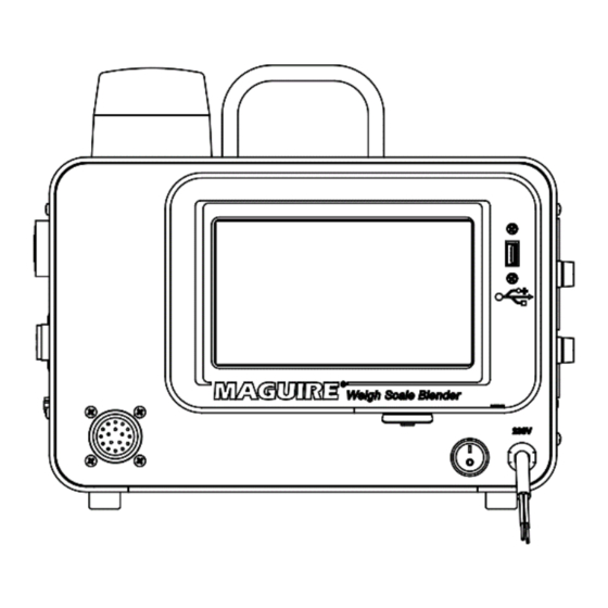
Page 20: Controller Parts Key
The Maguire Touchscreen Controller is designed to retrofit onto older Maguire Weigh Scale Blenders. The Maguire Touchscreen Controller has all of the features of the earlier 6811 (red display) and 12-12 (blue display) controllers and easily installs on all existing Weigh Scale Blenders. -
Page 21: Touchscreen Overview
Home Screen Title Bar Component Setpoint Hopper number Name Type Hoppers 9 - 12 START/STOP Button Specialized Operations Weigh Bin Mix Chamber High / Low Limits Print Center Nav bar Title Bar - The title bar displays: Model, current Operating Mode (blender, dispenser or Totalizer), date and time, Ethernet and USB status. - Page 22 Nav Bar Home Screen Pressing the Home Screen button from any other screen will return the operator to the main Home Screen. Alarm and Event Alarm and Event Log displays a history of alarms and other events with a date and time stamps and description. Live Diagnostics Live Diagnostics displays a cycle summary of detailed diagnostics information scrollable back through a history of...
- Page 23 Turning on Material Type Outputs This controller can control up to TWELVE (12) components; 1 through 12. Labeled: Component 1 through Component 12. Each Component is either a hopper or a feeder. All models are preset with their model specific component outputs turned ON. Components can be turned on or off.
- Page 24 ADDITIVE (PERCENT OF ALL NATURALS) Components designated ADDITIVE will be added as a percentage of all the NATURALS added together. For example: If component 4 is an ADDITIVE at 5 percent, then the above example now looks like this: Component 1, REGRIND, SET= 20, 20 percent, Component 2, NATURAL, SET= 10, 15.2 percent, Component 3, NATURAL, SET= 40, 61.0 percent, Component 4, ADDITIVE, SET= 05.0, 3.8 percent.
-
Page 25: Setting The Modes Of Operation
Modes of Operation Mode of Operation - Allows selection of the General Mode that the Blender will run in including: Blender (WSB, up to 12 components), Dispenser (WSD), or Totalizer with on-screen accumulated totals (WST). Additive as % of Natural or All Materials are % of Total Batch - This screen also allows selection of the blending Mode of Operation as: % of Natural or % of Total Batch. -
Page 26: Enabling Hopper Types
Enable and Set Hopper Type / Operation: Display will prompt for a password. Press Then press: (default: 22222) Press Blender Configuration Display will show the Device Configuration categories. Press Display will show the Component Type / Operation screen. Component Types Change Component Types: Press Component Navigation... -
Page 27: Example Of Making Settings
Examples of Making Settings Below are listed 4 different examples for possible settings users can make with the Maguire blender. Each example uses this formula: Rs = Regrind setting Ra = Regrind actual Regrind = Rs * Full weight As = Additive setting... - Page 28 Example 3: Blender: WSB 100 Series with 1000g Batch Materials: % of Batch % of Batch % of Batch % of Batch Application: All components as set as proportions of 100% of the batch. The total should always add up to 100%. When using settings that are % of total, always use all Regrind material types.
-
Page 29: Entering Component Settings
Entering Component Settings Settings are entered from the Home Screen by pressing any of the enabled component hoppers shown on the home screen. Press One of the hoppers Display will show the Component Setup screen. Press Display will show the Component Setpoint screen. Press To navigate through all enabled components. -
Page 30: Weigh Bin Setup
Weigh Bin Setup Press The Weigh Bin Display will show the Weigh Bin screen. (password protected) Weigh Bin Setup - Password protected screen for access to Weigh Bin related parameters Weight Limits FUL, MAX, TH, TL, WDD - See parameter on page 59 for more information. Vibration Control KDF, WDF, BER - See parameter on page 59 for more information. -
Page 31: Mix Chamber Setup
Mix Chamber Setup Press The Mix Chamber Display will show the Mix Chamber screen. Mix Chamber Setup - Password protected screen for access to mixer control parameters Mixer Control See related parameters starting on page 59 for more information. MIX – Time Mixer motor runs after weigh bin dump. JOG –... -
Page 32: Check Out Procedure And Diagnostics
Check Out Procedure As you go through this procedure, if WHAT SHOULD HAPPEN, doesn't happen, see next section, DIAGNOSTICS, for what to check. MB/100/200 series models (3K load cells), display all weights in 1/10 grams (xxxx.x). 400/900/1200/1800/2400/3000 series models (10K load cells) display weights in FULL grams, NO decimal point (xxxxx). - Page 33 Device number 1 will operate. Component 1 PRESS Press "1" repeatedly to observe operation. Device number 2 will operate. Component 2 PRESS Press "2" repeatedly to observe operation. For each dispense valve on your WEIGH SCALE BLENDER. REPEAT THIS SEQUENCE Up to 12 outputs are possible numbered Component 1 through to Component 12.
- Page 34 Check Out Procedure Diagnostics If display fails to come on at all: Check power to blender controller. Check your model numbers on the Red Metal Tag: If model number is not correct for you unit: see the next page, SELECTING CORRECT MODEL. If display field located center screen shows randomly drifting numbers: check to see load cells are plugged in.
-
Page 35: Load Cell Zero And Full Weight Calibration
Load Cell Zero and Full Weight Calibration The WSB has a set of load cells for weighing the weigh bin. The load cells must be calibrated periodically with zero and full weight calibrations for proper operation and accurate weight reporting. The zero calibration routine should be performed routinely to tare the load cells back to zero or near zero when necessary. - Page 36 Full Weight Calibration This unit was properly calibrated at the factory to match the load cells that were supplied with it. Rough handling of load cells and environmental conditions can affect loadcell accuracy. A full weight calibration of the load cells is recommended periodically especially if totals are collected from the blender.
-
Page 37: Material Flow Rate Calibration
Material Flow Rate Calibration If material is changed or hardware is changed (example: 1/2" auger changed to a 1" auger) and material meters at a much lower or higher rate than expected, the software may take 10 to 20 cycles to fully adjust. During this time cycles will take longer. The software will SELF ADJUST the flow rate or a Material Flow Rate Calibration can be done to set the flow rate immediately. -
Page 38: Micro Pulse Instructions
Micro Pulse Instructions Optional MICRO PULSE valves for low dosing (10 g or less) and are available as a VERTICAL VALVE on removeable hoppers and also as a HORIZONTAL SLIDE GATE dispense device. These instructions are for blenders equipped with a Micro Pulse device. Do not set the PO parameter if your blender not equipped with a micro pulse device. MICRO PULSE are typically installed on the 3 and 4 color and additive components. -
Page 39: Regrind Control
Regrind Control Regrind Control is a set of parameters that enhance control of regrind. PRN 00000 - Percent of Regrind to be Treated as Natural First digit: 0 = adds, 1 = subtracts ... additive to or from the regrind. Second digit: Regrind component. - Page 40 Full Explanation of Regrind Control Parameters Percent of Regrind to be Treated as Natural Allows for adding some ADDITIVE to one of the REGRIND portions. PRN can also be used to subtract a portion of ADDITIVE to reduce the overall total of ADDITIVE (typically used to compensate for over-colored regrind).
- Page 41 The last digit determines the adjustment rate. Zero in the last position means make the full adjustment immediately. Any value from 1 to 9 indicates the percentage adjustment that will be made each cycle when the level sensor condition changes. See RHL below for examples.
- Page 42 Example: RHL is set to 90 and 10 percent (RHL 09010). RLC last digit is set to zero, (RLC 10000). The "Regrind" thumbwheel switch is set to 25 percent (025). The Software logic is as follows: If material level is high, above the high sensor, the HIGH sensor is COVERED, (returns NO signal);...
-
Page 43: Instructions For Normal Operation
Instructions for Normal Operation: 1. Fill HOPPERS. 2. Turn POWER ON. Verify correct Settings, Types and Mode of Operation. 3. Press START Button. Blender will operate automatically, dispensing material until level sensor is covered. Use the STOP Button to stop the blender. Turn POWER off only on final shutdown. After several days of proper operation: Save the current configuration including all parameters to the User Backup Settings for future retrieval just in case software problems develop later. - Page 44 Restoring Parameters from Backup If software related problems develop later or a firmware update is applied to the controller, this routine will restore the last saved configuration of the blender stored within User Backup Settings. Press Display will prompt for a password. (default: 22222) Then press: Press System Configuration...
-
Page 45: Specialized Operations
Specialized Operations Specialized Operations are features accessible directly on the home screen. These features include: a quick access clear totals button on the VIEW totals screen, internal recipes, batch mode operation, setting tags for operator, recipe and work order and FAST mode used for increasing throughput speed. - Page 46 Specialized Operations - Full Explanation Clear View Totals Enable this feature to enable the CLEAR totals button on the View Totals screen. Pressing this button will: reset all component totals on-screen, reset all component totals in communication registers, and reset the cycle count back to zero. A clear bit in the Get Totals command will be set to 1.
-
Page 47: Recipes Database
Recipes Database When enabled a button labeled RECIPE will display on the controller main screen. This option allows operators to create, store, edit and load up to 99 detailed recipes within the blender’s onboard recipe database. The recipe database can be exported from a blender, edited in a plain text editor and imported into any WSB 4088 touchscreen controller. -
Page 48: Usb Recipe
USB Recipe USB Recipe is used for loading a recipe from a USB flash drive plugged into the USB controller. When enabled a button labeled USB RECIPE will display on the home screen. This option allows operators to create, store, edit and run a detailed recipe from a USB flash drive. At the beginning of each cycle, the blender controller will read the USB flash drive for the recipe file RECP_CMD.TXT. - Page 49 When recipe number 100 - 65535 is loaded from the TAG screen or communications, the controller will only set the recipe number. The Maguire G2 Software can be used to trigger an auto-download of a recipe to the blender from the G2 recipe database when the recipe number is set to 100-65535.
-
Page 50: Dispense Station
Dispense Station In Dispense Station Mode, material is dispensed up to a target weight and then the Dispense Station stops and alarms. Dispense Station is enabled under System Configuration, Mode of Operation. When in Dispense Station mode, a button labeled "Dispense Station" will be at the bottom center of the Home Screen. -
Page 51: Operator Access
Operator Access When enabled, Operator Access will limit access to functions of the blender by prompting for the operator password. All other functions of the blender will be restricted. Default Operator Access password is: 11111. Also see Changing Passwords below. Display will prompt for a password. -
Page 52: Change Passwords
Changing Passwords Access to the controller is limited by one or two passwords. Access to Setup information is restricted by an Admin Password (default password is: 22222). If Operator Access is enabled (see above), access to commonly used functions are further restricted with the Operator Password. If security is important and restricted access is desired, it is important to change the passwords. -
Page 53: Communications
502. For more information on Modbus TCP, see the Maguire Modbus register mapping document. MLAN Protocol (Maguire Local Area Network) – MLAN is a protocol consisting of commands that allows two-way communications to the Maguire Weigh Scale Blenders. All Maguire Weigh Scale Blenders dated back to 1992 contain the essential MLAN commands for basic control and data collection while newer Maguire controllers contain additional commands for enhanced control and data collection. - Page 54 Setting the IP Address, Subnet Mask, Gateway Press Display will prompt for a password. (default: 22222) Then press: Press Display will show the System Configuration categories. Press Communications Display will show the System Communications categories. Press TCP/IP Configuration Display will show the TCP/IP Configuration screen. On this screen, enter the IP Address, Subnet Mask and Static IP Default Gateway using the keypad to enter the number...
-
Page 55: Automated Control
Automated Control Automated Control is enabled using Modbus register 40151 or from the Setup menu under: Setup, System Configuration, Communications, Automated Control. Enabled or Disabled. When enabled, Automated Control gives enhanced start and stop control of the blender over Modbus TCP and status feedback of the blenders current state. -
Page 56: Setup Menu Map And Brief Explanation
Setup Menu Map – Brief Explanation This section contains a brief explanation of the Setup menu. For detailed information see Setup Menu Full Explanation starting on page 58. ► Setup (password protected) – Settings and Options Menus ► Blender Configuration – Blender specific settings ►... - Page 57 User Settings - Save / Restore User entered Settings ► Restore Factory Defaults - Restores factory loaded settings ► Factory Access - Factory Access Only ► Firmware Updates - Reads USB drive for updates, selects and updates firmware. Contact Maguire Products Inc. for updates.
-
Page 58: Menu Map - Full Explanation
Setup Menu – Full Explanation Setup is a password protected area for accessing Blender or System specific configuration settings. Setup is accessible from the main screen by pressing: Press Display will prompt for a password. (default: 22222) Then press: Parameters – All WEIGH SCALE BLENDER controllers operate according to certain internal PARAMETERS. -
Page 59: Parameters Introduction
Blender Configuration Parameters Setup > Blender Configuration > Parameters Parameters Introduction Parameters – All WEIGH SCALE BLENDER controllers operate according to certain internal PARAMETERS. Because customer requirements vary widely, we have made a wide range of parameters accessible for change through the touchscreen. - Page 60 Regrind % to treat as Natural Regrind Control Regrind Level Control High / Low Level Control Additive as a Percent of Total Additive Control Percent of Additive to Regrind Mix Time Mixer Control Jog Time Air Drive Mixer Timing Flow Control Delay Open Load Cell Limits Load Cell Low Load Cell High...
-
Page 61: Parameters - General -Explanation
Parameters – General –Explanation 200 series settings shown as example settings DLY 02000 CYCLE START DELAY - Delay before cycle start. (milliseconds) Time in milliseconds that the sensor must be uncovered before cycle start. Minimum of 02000 (ms) is recommended. With low throughput, increasing DLY may allow better mixing if needed. - Page 62 RAC 000000 Regrind Auto Control This is a Six-digit parameter. 1st digit is the regrind component 2nd and 3rd digits are the cycle count Last 3 digits are the % to increase current setting by. Example: 110100 - Regrind #1, 10 cycles increase setting by 100%. Current setting 25%, increases to 50%.
- Page 63 detection checks for a gram change in weight (weight gain for valve leak, weight loss for weigh-bin leak) three times in a row. Then, to minimize false positives, the logic does the same check again as a verification step. WDD is broken into two fields: digits 2+3 are the weigh bin leak tolerance in grams.
- Page 64 MCT – Monitor Cycle Time Alarm For Throat Mount Applications Only Alarms if cycle exceeds normal cycle time by multiplier or by time in seconds. 00000 = Inactive First two digits (02xxx) is multiplier of previous cycle time. Last three digits (xx060) is time in seconds over previous cycle time. Silence Alarm button or next cycle resets the alarm.
-
Page 65: Parameters - Component - Explanation
Component Parameters Explanation There are 12 Groups of parameters, one group per component. In parameter printouts the first digit in the parameter name is the component number. RP 00010 Retry by Percent - Shortage RD 00300 Retry by Gram - Shortage RP is the shortage expressed as a PERCENT of the target dispense weight and RD is the shortage expressed in GRAMS. - Page 66 WT Weight Dispense Rate (grams/second) TI Time Set AUTOMATICALLY by the Flow Rate Calibration routine WT and TI set the flow rate or dispense rate of each material. These can be set manually, set by the Flow Rate Calibration routine, and adjust automatically after each cycle.
- Page 67 Component Setpoint Control – High / Low Limit A component’s maximum and/or minimum setting can be limited by an upper and/or lower limit using the component parameters SE (upper) and SL (lower). When a limit is set, the setpoint will be capped at the lower or upper limit. When an upper or lower limit is set for a component, a Setpoint Limit Indicator will be visible on the components setpoint field and will indicate if the setting is above, below or within the upper and/or lower setpoint limits.
-
Page 68: Parameter Default Settings
USB port and select “Print Parameters” in the Print Center. A file labeled WSBPARAM.TXT will be written to a folder named “maguire” on the USB flash drive. In this file the ROM column is the default parameters for the selected model. RAM is the current parameters in use while EEPROM is the parameters saved through a power cycle. - Page 69 Restoring Parameters from Backup To restore parameters from backup, follow these steps. Note: If parameters are restored without a prior save of parameters, default parameters for your model will be loaded. Press Display will prompt for a password. (default: 22222) Then press: Press System Configuration...
- Page 70 Blender Configuration - Continued Specialized Alarms Setup > Blender Configuration > Specialized Alarms Maximum Weight Exceeded Alarm – When enabled, if the MAX (parameter) weight is exceeded, the system will stop and the Alarm will sound. This might occur if a valve sticks open or slightly open. Normally the system recovers automatically from such events with only the one batch blended incorrectly.
- Page 71 Dispense Order - Specify the dispense order of active components from largest to smallest, smallest to largest or custom order. When the Blend Mode is set to “% of Natural” the dispense order controls only the natural components. When the Blend Mode is set to “% of Total Batch”, the dispense order can control all components.
- Page 72 Press To adjust the first Try percentage. You may change the 85 by entering a different number using the arrow keys. Too low a setting will just add time. Too high will cause occasional overshooting. Press To Save and exit or press the red X to cancel and exit.
- Page 73 System Configuration Modes of Operation Setup > System Configuration > Modes of Operation Modes of Operation - Blender Modes: • Blender – Blending up to 12 components • Dispenser – Operates Blender as a Weigh Scale Dispenser (WSD). • Totalizer – Operates Blender as a Weigh Scale Totalizer (WST). •...
- Page 74 Print Cycle History – Prints diagnostic data of the last 250 cycles to USB. Can be printed as fixed width plain text file or as a CSV file with or without the column headers (titles). Print Totals Interval - Enables automatic print of totals to USB at a specified interval (see PRT parameter).
- Page 75 Alarm and Event Log – Also accessible from the home screen alarm button. Displays the Alarm and Event Log screen. This screen shows the stored history of alarms, critical events, power on events, and other events. Press the upper or lower half of the event display windows to page up or page down. Alarms can be silenced from this screen.
-
Page 76: Monitoring Blender Accuracy
To print the cycle data to USB. Requires a folder named “maguire”. Press To write the current cycle on the screen to USB. Requires a folder named “maguire”. Press Print Cycle Diagnostics – Automatically writes cycle data after every cycle to a file on the USB Flash Drive in a plain text file format or CSV spreadsheet format. -
Page 77: Interpreting The Cycle Printout
Interpreting the Cycle Printout 10 or 20 cycles of data can tell a lot about blender performance. The following explains how to interpret the data. A single cycle printout looks like this: * 11/03/18 * *16:17:53* **ID# 051** 000000 RECIPE 00000 OP 000 **1 R 20.0** **2 N... -
Page 78: Troubleshooting With The Printout
Troubleshooting with the Print Diagnostics TOTAL BATCH WEIGHT: Check the TOTAL batch weight to confirm the blender model. 2000 grams indicates 200 series model. 400, 1000, and 2000 gram totals indicate models that use 3 K load cells, which means output information is in 1/10's of grams. - Page 79 In the component 4 column, 1600 and 32000 indicate a flow rate of 50 grams per second. DATA line 3 dispense weight of 0.0 for component 4 and the component 4 is set to 00.0 percent confirming that component 4 is not dispensing material. The following information will help you determine what devices are in place on a blender.
- Page 80 DISPENSE TIMING: (DATA line 3) The second number is the number of milliseconds calculated to dispense the material. If these times are consistent but the weight of the first dispense varies, then the material does not flow well, or consistently. Another possibility is excessive vibration or interference with the weigh bin.
-
Page 81: Parameter Settings Printout
Print Parameters, Print Alarm and Events, Print All. Press Print Parameters System will print parameters to USB to a file labeled: PRINTER.TXT located in a folder named “maguire”. Press To save and exit or press the red X to cancel and exit. - Page 82 Weight Certification file. The Weight Certification file is written to a USB flash drive into a folder named maguire. The file output format is plain text ASCII with a file name as W<ID>CERT.txt. (example: W001CERT.txt for ID number 1).
-
Page 83: Material Usage Printout
Material Usage Printout Pressing the VIEW key on the Home screen followed by the Print to USB button will cause all material usage totals to be printed. These totals are since the last time printed, and since the last time cleared. The printout looks like this: DATE TIME... -
Page 84: Troubleshooting - What To Do
Print Parameters, Print Alarm and Events, Print All. Press Print Parameters System will print parameters to USB to a file labeled: PRINTER.TXT located in a folder named “maguire”. Press To save and exit or press the red X to cancel and exit. -
Page 85: Alarms - Cause And Solution
Alarms - Cause and Solution Typically, problems are indicated by an alarm condition on the Blender controller’s display with an audible alarm and a flashing strobe light. The following alarm troubleshooting chart will describe the alarm condition and possible causes and solutions. Alarm Display: Troubleshooting: COMPONENT ALARM... - Page 86 ZERO TARE ALARM Problem: Load Cells outside of acceptable (former: DUMP ALARM) Calibration. Weigh bin empty weigh above tare high upper limit (TH parameter) or ALARM CODE:15 below tare lower limit (TL parameter). If above TH (upper limit) weigh bin dump valve opens and closes repeatedly. Possible causes: There is material in the weigh bin that will not dump out.
- Page 87 MCT PARAMETER ALARM Problem: Cycle time exceeds previous cycle time by value set in MCT parameter. ALARM CODE:23 The MCT parameter when used, monitors sequential cycle times and alarms if a cycle time exceeds the previous cycle time by an amount that is not consistent with proper operation.
- Page 88 REGRIND LESS THAN 100% Problem: All Regrind Recipe or Percent of Total Recipe settings add up to less than 100%. ALARM CODE:31 When Blend Mode of Operation is set to “% of Total Batch” or all component types are set to REGRIND, the settings must add up to 100% (within the range of 99.0% to 100.0%).
-
Page 89: Typical Problems
Typical Problems These problems are based on phone calls that we have received from Weigh Scale Blender users. The display does not read close to zero when power is turned on, bin empty (plus or minus 10 grams). • The load cells are not plugged in. •... -
Page 90: Mix Problems
Load Cell weight readings are not holding steady. They vary as much as 100 grams from second to second. • Static induced poor grounding of load cells. See Wiring Considerations. • If TARE weights are not steady, something may be physically interfering with free movement of the weigh bin and load cells. - Page 91 On model WSB-940, be sure the weigh bin has two baffles installed. These ensure horizontal layering (as opposed to side by side layering) of materials prior to dropping into the mix chamber. Bulk density and pellet shape differences, specifically smooth virgin pellets mixed with square higher density color pellets, can separate when dropped onto a sloping pile, as exists in a hopper, Gaylord, or surge bin.
-
Page 92: Increasing Throughput
Increasing Throughput A correctly sized blender should have throughput that always exceeds your process requirements. If, for some reason, your blender is not keeping up, here are a few ways to increase throughput. 1. If your blender is equipped with a flow control slide gate, under the blender, this will reduce throughput up to 25 percent. -
Page 93: Normal Operating Sequence
Turn POWER ON: A boot up splash screen displays showing MAGUIRE WSB with the current firmware version displayed in the lower right corner. A status bar and Synchronizing with WSB displays at the bottom. The controller should then display the home screen. The weigh bin weight reading will display at the center of the home screen on the image of the weigh bin. - Page 94 ADDITIVES third: The ADDITIVE dispenses occur last in the sequence. Each dispense must meet requirements set by internal parameters. MATERIAL RUNS OUT: If any material runs out or is not enough to meet criteria set by parameters then the process will NOT CONTINUE past this component. RETRIES of this dispense will occur indefinitely until the full dispense occurs or the STOP button is pressed followed by the ABORT button.
-
Page 95: Verifying Load Cell Function
VERIFYING LOAD CELL FUNCTION Most Problems are related to LOAD CELL function. There are several ways to VERIFY that the load cells are functioning properly. The slightest touch on the weigh bin should result in a change in the readout. If this is not the case, something is wrong. -
Page 96: Load Cell Raw Signal Readout
Load Cell Raw Signal Readout Press Setup, System Configuration, Diagnostics, Load-Cell Diagnostics to check this RAW number for several seconds. Load cells put out a very small voltage that varies slightly as the load cell is deflected. This voltage is converted to a pulse train and these pulses are counted for 1 full second to determine a weight load with a range of counts from 0 to approximately 249,850. -
Page 97: Backup, Restore, Factory Reset
Backup, Restore, Factory Reset Locations of stored Blender settings and their purpose There are 3 memory areas where Blender settings are stored. These options are accessible by pressing Setup, System Configuration, Resets, User Settings. 1. Restore User Settings - The current settings in use. When you make parameter changes and/or enable features, the changes (if any) are recorded into the user-settings when you exit OPTIONS mode. -
Page 98: Updating Controller Firmware
If necessary, the firmware in the WSB can be updated using a firmware update supplied by Maguire Products. Firmware updates use the USB port located to the right of the control screen. The following instructions detail how to do a firmware update. -
Page 99: Loto, Cleaning, Maintenance
LOTO, Cleaning, Maintenance Pneumatic and Electrical LOTO The blender should be pneumatically and electrically locked out prior to any Cleaning/Maintenance/Repair of the blender. Pneumatic Lockout/Tagout Points Disconnect compressed air supply before performing Cleaning/Maintenance/Repair. If the weigh scale blender is equipped with a manually operated pneumatic valve actuator, use this lockout/tagout valve to perform a pneumatic lockout/tagout. - Page 100 Manual Operations – Manual Operations in the touchscreen controller provides manual operation of the valves, augers, weigh bin an mix motor/blades for manual cleanout and testing procedures. To access Manual Operations press: Setup, Blender Configuration, Manual Operations. The device is ON/Open when the button is green. The device is OFF/Closed when the button is red.
-
Page 101: Maintenance And Preventative Maintenance
Maintenance and Preventative Maintenance Air Pressure Recommendations: Approximately 5.5 bar (80 psi) is recommended for most models. 4.1 bar (60 psi) is recommended for: Micro Blender, 140R, 240R and 440R. The coalescing filter is a final attempt to dry the air to protect the valves and solenoids from moisture contamination. - Page 102 Weigh Bin Clearances – Free Movement of Weigh Bin Carefully examine all the parts of the weigh bin and the bin hanging bracket to be sure that the weigh bin or weigh bin hanging bracket does not come in contact with windows or guards.
-
Page 103: 17 Pin Amphenol Connector Pin Assignments
17 pin Amphenol connector Pin assignments This table describes the pin assignment to device of the 17 pin Amphenol connector with factory wire color assignment. 17 pin Amphenol connector This pin goes to the to drive this external device: wire color outside world through this connector: 17 pin Amphenol connector... -
Page 104: Technical Drawings, Electrical Diagrams, Pneumatic Diagrams
Technical Drawings... - Page 116 FCA INSTALLATION DIAGRAM...
- Page 117 WSB 4088 IO wiring diagram 120V...
- Page 118 D-WSB-E0001 - Electrical Diagram, WSB Export, Single Phase...
- Page 119 D-WSB-E0002 - Electrical Diagram, WSB Export, 3-Phase...
- Page 120 D-WSB-E0003 - Electrical Diagram, WSB Export, 1800 3-Phase...
- Page 121 D-WSB-E0004 - Electrical Diagram, WSB Export, Maxibatch...
- Page 122 WSB Single Phase Motor Safety Circuit WSB 3-Phase Motor Safety Circuit WSB-18 3-Phase Motor Safety Circuit...
- Page 123 D-WSB-P0001 - Pneumatic Diagram, WSB, with Non-Removable Hoppers...
- Page 124 D-WSB-P0002 - Pneumatic Diagram, WSB, with Removable Hoppers...
-
Page 126: Dimensions And Weight By Model
Note: Weights and dimensions can vary based on the accessories and hopper configuration. The following values are for example only of the specific models listed. For more specific information about your configuration, please contact Maguire Products Inc. Model Overall Dimensions (WxDxH) -
Page 127: Flexbus Lite Table Of Contents And Overview
Flexbus Lite Integrated Loading System The Flexbus Lite Loading System is integrated into the Maguire 4088 Weigh Scale Touchscreen Controller enabling local control of a single pump and up to 9 receivers. This chapter describes the Flexbus Lite Loading System. -
Page 128: Flexbus Lite Setup And Configuration
Flexbus Lite Home Screen Overview Live View Panel (gray area) - Displays the live view of Receivers Navigation Menu Home Screen Display Pump Event Log and Alarm History Switch to WSB Home Screen Setup (password protected) Receivers Pump Navigation / Setup of all Receivers Setup of Pump Flexbus Lite Setup and Configuration Flexbus Lite uses a MAC address to individually identify each Flexbus pump and... - Page 129 Flexbus, a T-drop, a position hub, pump module, and necessary cabling. Please see the Flexbus Lite component map on page 146 for setup details. How to enabled Flexbus Lite in the Maguire Weigh Scale Blender Press Display will prompt for a password. (default: 22222)
- Page 130 Flexbus Lite System Setup Screen Pump assignment is set through the SETUP screen. The setup screen is accessed by pressing the Setup button on the right side of the screen. On the HOME Pressing the SETUP button prompts for a password. screen, PRESS: Enter the password (default password is 22222) 22222...
-
Page 131: Flexbus Pump Assignment
Pumps must be assigned before Receivers. Flexbus Lite (part of the Maguire 4088 TS Weigh Scale Blender) controls a single pump. The Flexbus System can control of to 5 pumps. If you have two or more pumps (Flexbus only), turn... - Page 132 While in the Setup screen you can go straight to setting up Receivers without re-entering the password. To enter the Receivers assignment screen. Next Page for Receivers Assignment PRESS: instructions. Otherwise, to exit SETUP... PRESS: To exit the Setup screen.
-
Page 133: Receiver Assignment
Receiver Assignment NOTE: If you are already entered into SETUP, skip the password step and go to the below. On the HOME Pressing the SETUP button prompts for a screen PRESS: password. Enter the password (default password is 22222) 22222 PRESS: Press to confirm password. -
Page 134: Receiver Configuration
Receiver Configuration The Receiver configuration screen is accessible from the Home screen. Pressing a receiver on the Home Screen, takes you to the Receiver's Configuration screen. The receiver that you are configuring is identified by the Receiver's ID number on the receiver images on this screen. - Page 135 Load Retry - The number of times the receiver will try to successfully load material and satisfy the sensor. Exceeding this retry count will cause the receiver to alarm. Dump Time - The time in seconds that the receiver will remain open during the dump cycle.
-
Page 136: Pump Configuration
Pump Configuration Pressing the pump button in the right navigation takes you to the Pump overview screen and then pressing a pump in this overview screen will open the Pump's Configuration screen. The pump that you are configuring is identified by the pump's ID label on the pump's image on this screen. - Page 137 Pump Control Pump Status Panel - This panel displays messages and pump status and allows the pump to be turned OFF or ON. The pump symbol can display the following states: Pressing the pump symbol toggles the pump OFF or ON. Message will display PUMP OFF.
- Page 138 Pump Configuration Fields Blowback - Blowback is a pulse of air to clear the filter. Blowback has two configuration fields. Skip cycle defines the number of Bypass cycles skipped between each blowback pulse. Default for Skip Cycle is 10. Setting Skip Cycle to 0 (zero) will pulse every time.
-
Page 139: Removing Receivers Or Pumps
Removing Receivers from the configuration If a receiver needs to be removed from the configuration, it can be removed using this procedure. On the HOME Pressing the SETUP button prompts for a screen PRESS: password. Enter the password (default password is 22222) 22222 PRESS: Press... -
Page 140: Flexbus System Setup Options
Set Date and Time Set Screen Brightness Update Receiver and Pump Firmware Requires a firmware update provided by Maguire Products Inc. Copy firmware (.XUF file) to USB and insert USB into the controllers USB port. Press this Update button. Press the green check to start the update. -
Page 141: Flexbus Main Screen Details
Flexbus Lite Main Screen Live Status Panel Navigation Menu Displays the live status of all receivers. See below for receiver symbol representation. Returns to Home screen from any screen. Display Pump Changes the Live view panel to the Pump Alarm History Displays red when there is an alarm notification. - Page 142 What the Receiver Symbols Represent: Receiver is online and idle. Lost communication with receiver. Cause may be receiver's power is off or a disconnected communication wire. Receiver is inactive. Receiver is alarming. Virgin material filling Regrind material filling receiver. receiver. Demand for material.
-
Page 143: Flexbus Wiring Diagram
Flexbus Lite Wiring Diagrams... -
Page 146: Flexbus Lite Component Map
Flexbus Lite Component Map... -
Page 147: Decommissioning And Disposal
& National regulations. Disclaimers Intended Use - The intended use of the Maguire Weigh Scale Blenders is specifically for blending of raw and recycled plastics materials and plastics additives. The Maguire blenders should not be used for applications outside of the intended use. -
Page 148: Warranty
MAGUIRE PRODUCTS neither assumes nor authorizes any other persons to assume for it any other liability in connection with the sale of its Weigh Scale Blenders. -
Page 149: Technical Support And Contact Information
Tamworth Staffordshire B775DY Tel: + 44 1827 265 850 Fax: + 44 1827 265 855 Email: info@maguire-europe.com Maguire Products Asia PTE LTD Main Office 15 Changi North Street 1 #01-15, I-Lofts Singapore 498765 Tel: 65 6848-7117 Fax: 65 6542-8577 E-mail:...
Need help?
Do you have a question about the Weigh Scale Blender 4088 and is the answer not in the manual?
Questions and answers
How do you change Hopper number on the home screen
To change the hopper number displayed on the home screen of the MAGUIRE Weigh Scale Blender 4088, press the button that toggles between hopper views. The main home screen shows hoppers 1 through 8. To view hoppers 9 through 12, press the designated button. Press the same button again to return to hoppers 1 through 8. The display will also automatically switch to show hoppers that are currently operating.
This answer is automatically generated