Sign In
Upload
Download
Table of Contents
Contents
Add to my manuals
Delete from my manuals
Share
URL of this page:
HTML Link:
Bookmark this page
Add
Manual will be automatically added to "My Manuals"
Print this page
×
Bookmark added
×
Added to my manuals
Manuals
Brands
Toshiba Manuals
Barcode Reader
BV410T-GS02-QM-S
Owner's manual
Toshiba BV410T-GS02-QM-S Owner's Manual
Hide thumbs
1
2
3
4
5
6
Table Of Contents
7
8
9
10
11
12
13
14
15
16
17
18
19
20
21
22
23
24
25
26
27
28
29
30
31
32
33
34
35
36
37
38
39
40
41
42
43
44
45
46
47
48
49
50
51
52
53
54
55
56
57
58
59
60
61
62
63
64
65
66
67
68
69
70
71
72
73
74
75
76
77
78
79
80
81
82
83
84
85
86
87
88
89
90
91
92
93
94
95
96
97
98
page
of
98
Go
/
98
Contents
Table of Contents
Troubleshooting
Bookmarks
Table of Contents
Preface
Precautions for the Handling of Wireless Communication Devices
Table of Contents
Accessories
Names and Functions of Parts
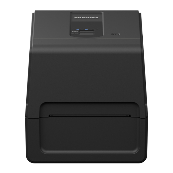
Exterior View
Printing Mechanism
Operation Panel
Power and Interface Panel
Preparing to Use the Printer
Setup Locations
When Purchasing the Power Cable
Connecting the AC Adapter/Power Cable
Connecting to a Computer
Turning the Printer ON/OFF
Turning on the Printer
Turning off the Printer
Loading the Media
Media Loading Procedure
Procedure for Loading Media When the Cutter Module Is Attached
Procedure for Loading Media When the Peel-Off Module Is Attached
Fanfold Paper Loading Procedure
Procedure for Loading Media When Using the External Media Stand
Loading the Ribbon (Thermal Transfer Method)
Adjusting the Position of the Media Detection Sensor
Confirming the Position of the Transmissive Sensor (Fixed)
Adjusting the Position of the Reflective Sensor (Movable)
Daily Maintenance
Cover
Print Head
Media Detection Sensors
Platen Unit
Media Housing
Cutter Module (Option)
Peel-Off Module (Option)
Troubleshooting
Error Messages (BV410T)
ERROR Lamp Status (BV420T)
If the Printer Does Not Operate Correctly
If the Media Are Jammed
If the Ribbon Is Cut off in the Middle
If the Ribbon Winds Become Disordered
Specifications
Printer
Media
RFID Tag
Ribbon
Replacing the Supplies
Media
Ribbon
Advertisement
Quick Links
1
Preparing to Use the Printer
2
Connecting to a Computer
3
Loading the Media
Download this manual
BARCODE PRINTERS
Owner's Manual
BV410
T-GS 2
BV410
T- TS 2
BV420
T-GS 2
BV420
T- TS 2
0
-QM S/BV410
-
0
-QM S/BV410
-
0
-QM S/BV420
-
0
-QM S/BV420
-
BV410T
T-GS 4
1
-QM S
T-TS 4
1
-QM S
T-GS 4
1
-QM S
T-TS 4
1
-QM S
BV420T
-
-
-
-
Table of
Contents
Previous
Page
Next
Page
1
2
3
4
5
Advertisement
Table of Contents
Need help?
Do you have a question about the BV410T-GS02-QM-S and is the answer not in the manual?
Ask a question
Questions and answers
Related Manuals for Toshiba BV410T-GS02-QM-S
Barcode Reader Toshiba BV410D-GS02-QM-S Owner's Manual
(48 pages)
Barcode Reader Toshiba BV420D-GS02-QM-S Owner's Manual
(48 pages)
Barcode Reader Toshiba BV420D-GL02-QM-S Owner's Manual
(39 pages)
Barcode Reader Toshiba BV420D Owner's Manual
(33 pages)
Barcode Reader Toshiba BV410D-GS14-QM-S Owner's Manual
(39 pages)
Barcode Reader Toshiba BV420D-GL14-QM-S Owner's Manual
(30 pages)
Barcode Reader Toshiba B-SX6T Series Owner's Manual
Toshiba barcode printer owner's manual (139 pages)
Barcode Reader Toshiba B-SX8T SERIES Owner's Manual
Toshiba barcode printer owner's manual (139 pages)
Barcode Reader Toshiba B-SA4TM Series Owner's Manual
(132 pages)
Barcode Reader Toshiba B-SX600 SERIES Owner's Manual
B-sx600 series (109 pages)
Barcode Reader Toshiba B-EX4 Series Maintenance Manual
(294 pages)
Barcode Reader Toshiba B-EX4T2 Series Manual
(70 pages)
Barcode Reader Toshiba B-SX4 Series Key Operations Manual
(136 pages)
Barcode Reader Toshiba B-FV4D SERIES Owner's Manual
(48 pages)
Barcode Reader Toshiba B-FV4 Series Manual
(303 pages)
Barcode Reader Toshiba B-EV4D-GS24-CUS-R Owner's Manual
(43 pages)
This manual is also suitable for:
Bv410t-gs14-qm-s
Bv410t- ts02-qm-s
Bv410t-ts14-qm-s
Bv420t-gs02-qm-s
Bv420t-gs14-qm-s
Bv420t-ts02-qm-s
...
Show all
Bv420t-ts14-qm-s
Table of Contents
Save PDF
Print
Rename the bookmark
Delete bookmark?
Delete from my manuals?
Login
Sign In
OR
Sign in with Facebook
Sign in with Google
Upload manual
Upload from disk
Upload from URL


Need help?
Do you have a question about the BV410T-GS02-QM-S and is the answer not in the manual?
Questions and answers