Table of Contents
Advertisement
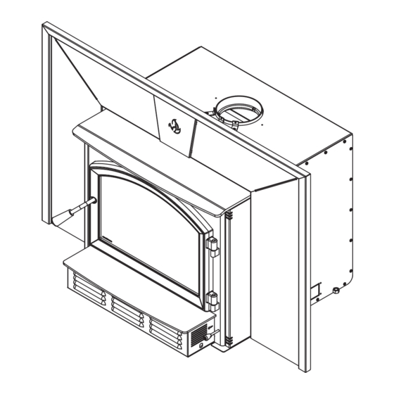
SOLUTION 3.5 INSERT
CONTACT LOCAL BUILDING OR FIRE OFFICIALS ABOUT RESTRICTIONS AND INSTALLATION INSPECTION REQUIREMENTS IN
THE AREA.
READ THIS ENTIRE MANUAL BEFORE INSTALLATION AND USE OF THIS WOOD INSERT. FAILURE TO FOLLOW THESE
INSTRUCTIONS COULD RESULT IN PROPERTY DAMAGE, BODILY INJURY OR EVEN DEATH.
READ AND KEEP THIS MANUAL FOR REFERENCE
Printed in Canada
Installation and
(EB00062 Model)
Operation
Manual
Safety tested according to
ULC S628, UL 1482 and
UL 737 by an accredited
laboratory.
US Environmental Protection
Agency phase II certified
wood insert compliant with
2020 cord wood standard.
EPA
< ≤
2.5
g/h
2022-10-06
46183A
Advertisement
Table of Contents

Related Manuals for Enerzone SOLUTION 3.5 INSERT


Summary of Contents for Enerzone SOLUTION 3.5 INSERT
- Page 1 Installation and Operation Manual SOLUTION 3.5 INSERT (EB00062 Model) Safety tested according to ULC S628, UL 1482 and UL 737 by an accredited laboratory. US Environmental Protection Agency phase II certified wood insert compliant with 2020 cord wood standard. < ≤...
- Page 3 It is also highly recommended to register the warranty online at https://www.enerzone-intl.com/en/warranty/warranty-registration/ Registering the warranty will help to quickly find the information needed on the unit.
-
Page 4: Table Of Contents
TABLE OF CONTENTS PART A - OPERATION AND MAINTENANCE ................7 1. Safety Information ........................7 2. General Information ........................ 8 2.1 Performances ......................... 8 2.2 Specifications ......................... 9 2.3 Dimensions ........................10 2.4 EPA Certification Loading ....................12 2.5 Materials ........................14 2.6 Zone Heating .........................14 2.7 Emissions and Efficiency ....................15 3. - Page 5 Appendix 5: Optional Fire Screen Installation ................49 Appendix 6: Air Tubes and Baffle Installation ................50 Appendix 7: Removal Instructions .................... 52 Appendix 8: Exploded Diagram and Parts List ................ 53 ENERZONE Limited Lifetime Warranty ..................56 Dealer: Installer: Phone Number: Serial Number: Installation and Operation Manual - Solution 3.5-I...
- Page 6 CERTIFICATION PLATE Page 6 Installation and Operation Manual - Solution 3.5-I...
-
Page 7: Part A - Operation And Maintenance
PART A - OPERATION AND MAINTENANCE 1. Safety Information • This insert has been tested for use with an open door in conjunction with a fire screen, sold separately. The door may be opened, or fire screen removed only during lighting procedures or reloading. -
Page 8: General Information
2. General Information Performances Values are as measured per test method, except for the recommended heating area, firebox volume, maximum burn time and maximum heat output. Models Solution 3.5-I (EB00062) Fuel Type Dry Cordwood Combustion technology Non-catalytic Recommended heating area (sq. ft. 1,000 to 2,700 ft (93 to 251 m Overall Firebox Volume... -
Page 9: Specifications
Specifications Recommended log length 16 in (406 mm) east-west Maximum log length 22 in (560 mm) east-west Flue outlet diameter 6 in (150 mm) Recommended connector pipe diameter 6 in (150 mm) Type of chimney ULC S635, CAN/ULC-S640, UL 1777 Minimum chimney height 12 feet Baffle material... -
Page 10: Dimensions
Dimensions 4 1/2" 18 1/2" 30 3/8" 116mm 472mm 773mm 28 3/4" 731mm 14 3/8" 366mm 7 1/8" 182mm 6" ø 153mm 27 3/4" 706mm Top View Side View - Minimum Insert Projection 1 3/8" 21 3/4" 36mm 552mm 12 1/2" 318mm 18 3/4"... - Page 11 10 5/8" 269mm 19" 483mm Door Opening 3/8" 10mm 3/16" 12 7/8" 326mm 22 7/8" 20 1/8" 581mm 510mm Front View - Combustion Chamber Side View - Combustion Chamber Installation and Operation Manual - Solution 3.5-I Page 11...
-
Page 12: Epa Certification Loading
EPA Certification Loading For EPA Certification testing, wood logs were 16 ± 1 inches long and the specie used was beech. 2.4.1 Air control The air control is located underneath the ash shelf. To open the air control, pull the air control handle completely (High). This will increase the burn rate. - Page 13 2.4.4 Logs placement The images below show how to place the logs in the combustion chamber as described previously. SECTION E-E SECTION E-E Installation and Operation Manual - Solution 3.5-I Page 13...
-
Page 14: Materials
Materials The SBI team is committed to protecting the environment, so they do everything they can to use only materials in their products that will have no lasting negative impact on the environment. The body of this insert, which is most of its weight, is carbon steel. Should it ever become necessary many years in the future, almost the entire insert can be recycled into new products, thus eliminating the need to mine new materials. -
Page 15: Emissions And Efficiency
Although the insert may be able to heat the main living areas of the house to an adequate temperature, it is strongly recommended to also have a conventional oil, gas or electric heating system to provide backup heating. The success of zone heating will depend on several factors, including the correct sizing and location of the insert, the size, layout and age of the home and the climate zone. -
Page 16: Tree Species
Tree Species The tree species the firewood is produced from is less important than its moisture content. The main difference in firewood from various tree species is the density of the wood. Hardwoods are denser than softwoods. Homeowners with access to both hardwood and softwood use both types for different purposes. Softer woods make good fuel for mild weather in spring and fall because they light quickly and produce less heat. -
Page 17: Drying Time
Drying Time Firewood that is not dry enough to burn is the cause of most complaints about wood inserts. Continually burning green or unseasoned wood produces more creosote and involves lack of heat and dirty glass door. Firewood with a moisture content between 15% and 20% will allow the insert to produce its highest possible efficiency. -
Page 18: Operating The Insert
4. Operating the Insert This wood heater has a manufacturer-set minimum low burn rate that must not be altered. It is against federal regulations to alter this setting or otherwise operate this wood heater in a manner inconsistent with operating instructions in this manual. Before using the insert, the following steps should be completed : •... -
Page 19: Blower
Blower A blower is already installed on this insert. It is located underneath the ash lip, in front of the insert. Its function is to increase airflow through the heat exchanger and improve hot air circulation in the room. When used regularly, the blower can provide a small increase in efficiency, up to 2%. -
Page 20: Burning Wood Efficiently
5. Burning Wood Efficiently First Use Two things happen when burning the first few fires; the paint cures and the internal components are conditioned. As the paint cures, some of the chemicals vaporize. The vapors are not poisonous, but they smell bad. Fresh paint fumes can also trigger false alarms in smoke detectors. When lighting the heater for the first few times, it may be wise to open doors and windows to ventilate the house. -
Page 21: Combustion Cycles
Use four or five sheets of paper tied together and put them on top and around the kindling. Open the air intake control completely, ignite the paper and close the door. The down fire method has two advantages over the traditional method: first, the fire does not collapse on itself, and it is not necessary to add wood gradually since the combustion chamber is full before the fire is lit. -
Page 22: Rekindling A Fire
Rekindling a Fire When the temperature of the room is lower and all that remains is embers, it is time to reload. Remove excess ash from the front of the firebox and bring the ashes forward. Place a new load of wood on, and at the back of the embers. -
Page 23: Air Intake Control
Air Intake Control Once the firewood, firebox and chimney are hot, air intake can be reduced to achieve a steady burn. As the air intake is reduced, the burn rate decreases. This has the effect of distributing the thermal energy of the fuel over a longer period of time. - Page 24 5.7.3 High Output Fires When heating needs are high during cold weather, the fire should burn steadily and brightly. This is the time to use larger pieces of hardwood. Place the biggest pieces at the back of the firebox and place the rest of the pieces compactly. A densely built fire like this will produce the longest combustion this insert is capable of.
-
Page 25: Maintenance
5.7.6 Carbon Monoxide When there is no more flame in the firebox and there are still some unburned logs, check outside if there is smoke coming out of the chimney. If this is the case, it means that the fire is out of air to burn properly. - Page 26 The goal should be having a clear glass with no brown stains. If brown stains appear regularly on the glass, something about the fuel or the operating procedure needs to be changed. When brown streaks are coming from the edge of the glass, it is time to replace the gasket around the glass.
-
Page 27: Door
Cut the gasket to the required length. Pinch the gasket onto the glass in a U shape, all around the glass. Door In order for the insert to burn at its best efficiency, the door must provide a perfect seal with the firebox. - Page 28 6.3.2 Gasket It is important to replace the gasket with another having the same diameter and density to maintain a good seal. Remove the door and place it face-down on something soft like a cushion of rags or a piece of carpet. Remove the old gasket from the door.
-
Page 29: Exhaust System
3/32" Using a flat screwdriver, turn the adjustable hinge rods in the direction shown to adjust the doors. Using a flat screwdriver, turn the adjustable hinge rods in the direction shown to adjust the doors. Tighten Tighten all door hinge pressure screws when they are at the desired positions. Configurations 1-2-3- all door hinge pressure screws when they are at the desired positions. - Page 30 6.4.1 Cleaning frequency It is not possible to predict how much or how quickly creosote will form in the chimney. It is important, therefore, to check the build-up in the chimney monthly until the rate of creosote formation is determined. Even if creosote forms slowly in the system, the chimney should be cleaned and inspected at least once each year.
-
Page 31: Part B - Installation
PART B - INSTALLATION 7. Masonry Fireplace Requirements The masonry fireplace must meet the minimum requirements found in the building code enforced locally, or the equivalent, for a safe installation. Contact the local building inspector for requirements in the area. An inspection of the fireplace should include the following: Fireplace and Chimney Condition The masonry fireplace and chimney should be inspected prior to installation, to confirm that they are free from cracks, loose mortar, creosote deposits, blockage, or other signs of deterioration. -
Page 32: Safety Information And Standards
8. Safety Information and Standards • The information given on the certification label affixed to the appliance always overrides the information published, in any other media (owner’s manual, catalogues, flyers, magazines and web sites). • Mixing of appliance components from different sources or modifying components may result in hazardous conditions. -
Page 33: Clearances To Combustible Material
9. Clearances to Combustible Material When the insert is installed so that its surfaces are at or beyond the minimum clearances specified, combustible surfaces will not overheat under normal and even abnormal operating conditions. NO PART OF THE INSERT MAY BE LOCATED CLOSER TO THE COMBUSTIBLE THAN THE MINIMUM CLEARANCE FIGURES GIVEN. - Page 34 To determine the need to add floor protection (D) beyond the hearth extension (A), the following calculation must be done using the data in «Table 4 : Data for Floor Protection Calculation» this section: D = B - G, where G = A-C. HEARTH SLAB: HEARTH SLAB: NON-COMBUSTIBLE MATERIAL...
- Page 35 9.2.3 R Value There are two ways to calculate the R-value of the floor protection. First, by adding the R-values of materials used, or by the conversion if the K factor and thickness of the floor protection are given. To calculate the total R value from R values of the materials used, simply add the R-values of materials. If the result is equal to or greater than the R-value requirements, the combination is acceptable.
-
Page 36: Minimum Masonry Opening And Clearances To Combustibles
Minimum Masonry Opening and Clearances to Combustibles COMBUSTIBLE MANTEL SHELF COMBUSTIBLE TOP SURROUND FLOOR PROTECTION Masonry Opening and Clearances MINIMUM CLEARANCES MAXIMUM THICKNESS 19" (483 mm) 5" (127 mm) 9" (229 mm) 12" (305 mm) 27" (686 mm) 27" (686 mm) 84"... -
Page 37: The Venting System
The Venting System 10.1 General The venting system, made of the chimney and the liner inside the chimney, acts as the engine that drives the wood heating system. Even the best insert will not function safely and efficiently as intended if it is not connected to a suitable chimney and liner system. The heat in the flue gases that pass from the insert into the chimney is not waste heat. -
Page 38: Chimney Liner Installation
10.4 Chimney Liner Installation The use of a chimney liner (rigid or flexible) is RAIN CAP recommended to ensure the best performance. ensure an optimal draft, it is also strongly recommend RIGID LINER adding a minimum of 12" rigid liner between the top of 12"... - Page 39 The dealer may offer a liner fastening system, sold separately. Follow the installation instructions provided with the liner fastening system. Liner fastening system 10.5.2 Liner Offset Adapter A liner offset adapter, sold separately, can also be installed. This should only be installed if no other option is possible and if the total height of the fireplace and chimney is at least 20 feet.
-
Page 40: Minimum Chimney Height
10.6 Minimum Chimney Height The top of the chimney should be tall enough to be above the air turbulence caused when wind blows against the house and its roof. The chimney must extend at least 3 ft. (1 m) above the highest point of contact with the roof, and at least 2 ft.(60 cm) higher than any roof line or obstacle within a horizontal distance of 10 ft. -
Page 41: Supply Of Combustion Air
10.8 Supply of Combustion Air In Canada, wood inserts are not required to have a combustion air supply from outside. Research has shown that outside air supply do not compensate for the depressurization of the house and may not be sufficient to provide a supply of combustion air in windy weather. However, to reduce the risks against smoke spillage due to house depressurization, a carbon monoxide (CO) detector is required in the room where the insert is installed. -
Page 42: Appendix 1: Blower And Ash Lip Installation
APPENDIx 1: BLOWER AND ASH LIP INSTALLATION Install the ash lip (A) on the insert with three screws (B). Center the blower on the ash lip and push it against the firebox. Then push it until it clips. Page 42 Installation and Operation Manual - Solution 3.5-I... -
Page 43: Appendix 2: Fresh Air Intake Kit Installation
APPENDIx 2: FRESH AIR INTAKE KIT INSTALLATION Note : The fresh air intake kit may be installed on the right or left end side of the unit. Using pliers, remove the rectangular metal plate (A) retained by the micro-seals to clear the opening for the outside air intake. -
Page 44: Appendix 3: Faceplate And Trims Installation
APPENDIx 3: FACEPLATE AND TRIMS INSTALLATION Illustrations may vary by model, but the assembly method remains the same. Hardware included with the faceplate : • Bolts #10-24 x 1/2" (8x) • Decorative molding fasteners (2x) • Kit of molding brackets and screws (2x) • Nuts #10-24 (8X) Remove the faceplate extension (K) secured between the firebox and the convection air jacket. - Page 45 DETAIL B Partially thread the screws (H) on the trim’s Insert the superimposed brackets in the corner bracket (G) then superimpose the groove of each decorative trim (T), (U) and corner brackets (F) and (G) as shown. (V). Align the corners of the angled side of each trim, and then tighten the screws (S) to secure the trims.
- Page 46 Align the holes in the faceplate extension (M) with the holes in each faceplate side panels. Secure both assemblies together using 6 bolts (N) and nuts (O) provided. Page 46 Installation and Operation Manual - Solution 3.5-I...
- Page 47 Center the insert into the fireplace opening. 10. Align the notch in the faceplate extension with the bolt (R) welded to the air jacket located and slide the faceplate assembly just over the bolt’s head and washer (Q and P). Then push towards the fireplace.
-
Page 48: Appendix 4: Log Retainers Installation
APPENDIx 4: LOG RETAINERS INSTALLATION 2" 2" Page 48 Installation and Operation Manual - Solution 3.5-I... -
Page 49: Appendix 5: Optional Fire Screen Installation
APPENDIx 5: OPTIONAL FIRE SCREEN INSTALLATION In the United States or in provinces with a particulate emission limit (eg. US EPA), the use of woodstoves with the door open with a rigid firescreen is prohibited. Open the door. Hold the fire screen by the two handles and bring it close to the door opening. Lean the upper part of the fire screen against the top door opening making sure to insert the top fire screen brackets behind the primary air deflector. -
Page 50: Appendix 6: Air Tubes And Baffle Installation
APPENDIx 6: AIR TUBES AND BAFFLE INSTALLATION Starting with the rear tube, lean and insert the right end of the secondary air tube into the rear right channel hole. Then lift and insert the left end of the tube into the rear left channel. Align the notch in the left end of the tube with the key of the left air channel hole. - Page 51 Note that secondary air tubes (A) can be replaced without removing the baffle board (B) and that all tubes are identical. Installation and Operation Manual - Solution 3.5-I Page 51...
-
Page 52: Appendix 7: Removal Instructions
APPENDIx 7: REMOVAL INSTRUCTIONS For inspecting purposes, the insert may need to be removed. To remove the insert, follow these instructions: Unscrew the faceplate fastener (C) holding the faceplate (B) on the insert. Remove faceplate (B) by pulling on it. Remove the blower assembly (A). -
Page 53: Appendix 8: Exploded Diagram And Parts List
APPENDIx 8: ExPLODED DIAGRAM AND PARTS LIST DETAIL B DETAIL C Installation and Operation Manual - Solution 3.5-I Page 53... - Page 54 IMPORTANT: THIS IS DATED INFORMATION. When requesting service or replacement parts for this unit, please provide the model number and the serial number. We reserve the right to change parts due to technology upgrades or availability. Contact an authorized dealer to obtain any of these parts.
- Page 55 44085 RHEOSTAT KNOB 44087 RHEOSTAT NUT 44080 RHEOSTAT WITHOUT NUT (MODEL KBMS-13BV) SE46183 SOLUTION 3.5 INSERT MANUAL KIT PL34052 LINER FIXATION BRACKET AC01298 5"Ø FRESH AIR INTAKE KIT AC05959 METALLIC BLACK STOVE PAINT - 342 g (12oz) AEROSOL Installation and Operation Manual - Solution 3.5-I...
-
Page 56: Enerzone Limited Lifetime Warranty
Labour cost and repair work to the account of the manufacturer are based on a predetermined rate schedule and must not exceed the wholesale price of the replacement part. Shall your unit or a components be defective, contact immediately your ENERZONE dealer. To accelerate processing of your warranty claim, make sure to have on hand the following information when calling: •... - Page 58 Resale is strictly prohibited. The manufacturer may update St-Augustin-de-Desmaures (Québec) Canada this document from time to time and cannot be responsible G3A 2H3 for problems, injuries, or damages arising out of the use 1-877-356-6663 of information contained in any document obtained from www.enerzone-intl.com/en/ unauthorized sources. tech@sbi-international.com...
Need help?
Do you have a question about the SOLUTION 3.5 INSERT and is the answer not in the manual?
Questions and answers