Table of Contents
Advertisement
Quick Links
INSTALLATION
AND OPERATION
MANUAL
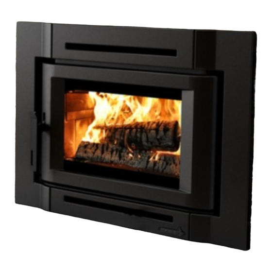
Destination 2.3
US ENVIRONMENTAL
PROTECTION AGENCY PHASE II
Insert
CERTIFIED WOOD
INSERT COMPLIANT WITH 2020
(EB00044 model)
CORD WOOD STANDARD
Safety tested according to ULC S628,
UL 737 and UL 1482 Standards
by an accredited laboratory
www.enerzone-intl.com
Stove Builder International Inc.
250, rue de Copenhague, St-Augustin-de-Desmaures
(Quebec) Canada G3A 2H3
After-sale service: 1-877-356-6663
E-mail: tech@sbi-international.com
READ AND KEEP THIS MANUAL FOR REFERENCE
This manual is available for free download on the manufacturer's web site. It is a copyrighted
document. Re-sale is strictly prohibited. The manufacturer may update this manual from
time to time and cannot be responsible for problems, injuries, or damages arising out of the
use of information contained in any manual obtained from unauthorized sources.
45925A
Printed in Canada
2022-10-06
Advertisement
Table of Contents

Related Manuals for Enerzone Destination 2.3


Summary of Contents for Enerzone Destination 2.3
- Page 1 INSTALLATION AND OPERATION MANUAL Destination 2.3 US ENVIRONMENTAL PROTECTION AGENCY PHASE II Insert CERTIFIED WOOD INSERT COMPLIANT WITH 2020 (EB00044 model) CORD WOOD STANDARD Safety tested according to ULC S628, UL 737 and UL 1482 Standards by an accredited laboratory www.enerzone-intl.com...
- Page 2 THANK YOU FOR CHOOSING THIS ENERZONE WOOD INSERT As one of North America’s largest and most respected wood stove and fireplace manufacturers, Stove Builder International takes pride in the quality and performance of all its products. We want to help you get maximum satisfaction as you use this product.
-
Page 3: Table Of Contents
Maintaining Wood Fires ....................20 5.3.1 General Advice ......................20 5.3.2 Ash Removal ....................... 20 5.3.3 Raking Charcoal ......................21 5.3.4 Firing Each New Load Hot ................... 21 5.3.5 Controlling the Air Intake....................21 Destination 2.3 Insert Installation and Operation Manual... - Page 4 General ........................... 36 10.2 Block-Off Plate ........................ 36 10.3 Suitable Chimneys ......................37 10.4 Liner installation ......................37 10.5 Liner Connection ......................38 10.5.1 Liner Starter Adaptor ....................38 10.5.2 Liner Offset Adaptor ..................... 39 Destination 2.3 Insert Installation and Operation Manual...
- Page 5 Appendix 6: Installation of Secondary Air Tubes and Baffle ... 49 Appendix 7: Removal instructions ..........51 Appendix 8: Exploded Diagram and Parts List ......52 ENERZONE LIMITED LIFETIME WARRANTY .. Erreur ! Signet non défini. Dealer: _______________________________________________ Installer: ______________________________________________...
- Page 6 CERTIFICATION PLATE Destination 2.3 Insert Installation and Operation Manual...
-
Page 7: Part A - Operation And Maintenance
This product can expose you to chemicals including carbon monoxide, which is known to the State of California to cause cancer, birth defects or other reproductive harm. For more information go to http://www.P65warnings.ca.gov Destination 2.3 Insert Installation and Operation Manual... -
Page 8: General Information
This appliance is officially tested and certified by an independent agency. Tested and certified in compliance with CFR 40 part 60, subpart AAA, section 60.534(a)(1(ii) and ASTM E3053-17. (10) Based on ALT-125 sent by EPA on February 28th, 2018. Carbon monoxide. (11) Destination 2.3 Insert Installation and Operation Manual... -
Page 9: Specifications
CAN/CSA-Z240 MH standard Tested and certified in compliance with CFR 40 part 60, subpart AAA, section 60.534(a)(1(ii) and ASTM E3053-17. Based on ALT-125 sent by EPA on February 28th, 2018. Destination 2.3 Insert Installation and Operation Manual... -
Page 10: Dimensions
Dimensions Destination 2.3 Insert Installation and Operation Manual... -
Page 11: Epa Certification Loading
(2" x 2") of wood in the firebox crossing them at the greatest possible angle. Criss cross 10 to 16 kindling wood pieces on the small pieces of wood in three layers at the greatest possible angle. Destination 2.3 Insert Installation and Operation Manual... -
Page 12: Zone Heating And How To Make It Work For You
The Benefits of Low Emissions and High Efficiency The low smoke emissions produced by the special features inside the Destination 2.3 firebox mean that your household will release up to 90 percent less smoke into the outside environment than if you used an older conventional insert. -
Page 13: The Sbi Commitment To You And The Environment
Disposal at a landfill is recommended. 3 Fuel MATERIALS THAT SHOULD NOT BE BURNED: COAL; − GARBAGE; − LAWN CLIPPINGS OR YARD WASTE; − MATERIALS CONTAINING RUBBER, INCLUDING TIRES; − MATERIALS CONTAINING PLASTIC; − Destination 2.3 Insert Installation and Operation Manual... -
Page 14: How To Prepare Or Buy Good Firewood
That is no longer true. You can successfully heat your home by using the less desirable tree species and give the forest a break at the same time. Destination 2.3 Insert Installation and Operation Manual... -
Page 15: Log Length
Drying happens faster in dry weather than in damp, maritime climates; • Drying happens faster in warm summer weather than in winter weather; • Small pieces dry more quickly than large pieces; • Split pieces dry more quickly than unsplit rounds; • Destination 2.3 Insert Installation and Operation Manual... -
Page 16: Judging Firewood Moisture Content
If necessary, before using the insert, the following steps should be completed: • Install the fresh air inlet (see "Appendix 1: Installing the optional fresh air intake kit") • Install the faceplate backing plate and the projection kit (see "Appendix 2: Installing the faceplate") Destination 2.3 Insert Installation and Operation Manual... -
Page 17: The Use Of A Fire Screen
Ensure the blower cord is not in contact with any surface of the insert to prevent electrical shock or fire damage. Do not run cord beneath the insert. Destination 2.3 Insert Installation and Operation Manual... -
Page 18: Burning Wood Efficiently
You can also set the switch to the manual position (1) to operate the blower at any time. Select the position (2) to manually stop the blower. Destination 2.3 Insert Installation and Operation Manual... -
Page 19: Conventional Method
Commercial fire starters can be used instead of a newspaper. Some of these starters are made of sawdust and wax and others are made of specialized flammable solid chemicals. Always follow the package directions when using. Destination 2.3 Insert Installation and Operation Manual... -
Page 20: Maintaining Wood Fires
Other waste should not be placed in this container. NEVER STORE ASHES INDOORS OR IN A NON-METALIC CONTAINER OR ON A WOODEN DECK. Destination 2.3 Insert Installation and Operation Manual... -
Page 21: Raking Charcoal
In addition, the flow rate of exhaust through the insert and flue pipe slows down, which increases the duration of the energy transfer of the exhaust gases. As the air intake is reduced, the flame slows down. Destination 2.3 Insert Installation and Operation Manual... -
Page 22: Fires Types
The flaming phase of the fire lasts for roughly the first half of the burn cycle and the second half is the coal bed phase during which there is little or no flame. Destination 2.3 Insert Installation and Operation Manual... -
Page 23: Logs Orientation
East-west loads allow a limited amount of wood since too many logs could cause them to fall on the glass. East-west loads, placed in a compact way, take a long time before breaking down. They are excellent for low-intensity, long-lasting fires in relatively mild weather. Destination 2.3 Insert Installation and Operation Manual... -
Page 24: Maintaining Your Wood Heating System
Replacing the Glass or the Glass Gasket» for installation. Always replace gaskets with genuine ones. See «Appendix 7: Exploded Diagram and Parts List». Do not abuse the glass door by striking or slamming shut. Do not use the insert if the glass is broken. Destination 2.3 Insert Installation and Operation Manual... -
Page 25: Door Adjustment
Tuck any loose fibres under the gasket and into the silicone. Close the door and do not use the insert for 24 hours. Destination 2.3 Insert Installation and Operation Manual... -
Page 26: Replacing The Glass Or The Glass Gasket
Before painting, the surface should be sanded lightly with sandpaper and then wiped off to remove dust. Apply two thin layers of paint. For best results, use the original paint, available in aerosol cans. Destination 2.3 Insert Installation and Operation Manual... -
Page 27: Firebricks
Inspection and cleaning of the chimney can be facilitated by removing the baffle. THE OPERATION OF THIS INSERT WITHOUT THE BAFFLE MAY CAUSE UNSAFE AND HAZARDOUS TEMPERATURE CONDITIONS AND WILL VOID THE WARRANTY. Destination 2.3 Insert Installation and Operation Manual... -
Page 28: Part B - Installation
Your local inspector should have information on whether older fireplaces are of adequate construction. OPENING SIZE: Refer to «Section 9.5 MINIMUM MASONRY OPENING AND CLEARANCE TO COMBUSTIBLE” for suitable size fireplace openings. Destination 2.3 Insert Installation and Operation Manual... -
Page 29: Safety Information And Standards
HEATER IN ANY FACTORY-BUILT FIREPLACE. Regulations Covering Insert Installation When installed and operated as described in these instructions, the Destination 2.3 wood insert is suitable for use in residential installations. The Destination 2.3 wood insert is not intended for installation in a bedroom. -
Page 30: Clearances To Combustible Material
(27009), supplied with the owner’s manual kit, indicating that the masonry hearth has been modified. It must be secured inside the masonry hearth, in a visible place and easy to locate. Destination 2.3 Insert Installation and Operation Manual... -
Page 31: Installation Of A Combustible Mantel Shelf
2'' (51 mm) or 4'' (102 mm) of the convection air jacket in front of the fireplace opening with the use of the projection kit. The choice of the configuration will depend on the previous installation instructions and compliance with building code. Destination 2.3 Insert Installation and Operation Manual... -
Page 32: Installation Raised Of 5" And Less
(F = 5" or less), an R-value equal to or greater than 1.00 is required and should extend at least 23" (584 mm) in front of the unit (B). Destination 2.3 Insert Installation and Operation Manual... -
Page 33: Installation Raised Of More Than 5
There are two ways to calculate the R-value of the floor protection. First, by adding the R-values of materials used, or by the conversion if the K factor and thickness of the floor protection are given. Destination 2.3 Insert Installation and Operation Manual... - Page 34 R by dividing the thickness of each material by its K value. Add R values of the proposed materials as shown in the previous example. Example: K value = 0.75 Thickness = 1 R value = Thickness/K = 1/0.75 = 1.33 Destination 2.3 Insert Installation and Operation Manual...
-
Page 35: Minimum Masonry Opening, Clearances To Combustibles
* Where a fresh air intake is needed, we suggest you add a minimum of 4" to the width of the minimum masonry opening. ** If projection kit is used L = 17 5/8" or 15 5/8". If installed without projection kit L = 19 5/8". Destination 2.3 Insert Installation and Operation Manual... -
Page 36: The Venting System
In Canada, the CSA B365 Standard permits «Roxul» type wool to be stuffed around the liner as it passes through the throat area as an alternative to a sheet metal block-off plate. However, this method is less efficient than using a plate. Destination 2.3 Insert Installation and Operation Manual... -
Page 37: Suitable Chimneys
If lag-bolts or anchors are to be used to secure the insert, the hole locations should be marked with the unit in place. Remove the insert and locate the anchors. Destination 2.3 Insert Installation and Operation Manual... -
Page 38: Liner Connection
(not included). The dealer may offer a liner fastening system (AC02006), sold separately. Follow the installation instructions provided with the liner fastening system. Destination 2.3 Insert Installation and Operation Manual... -
Page 39: Liner Offset Adaptor
1 m (3 ft.) above the highest point of contact with the roof, and at least 60 cm (2 ft.) higher than any roof line or obstacle within a horizontal distance of 3 m (10 ft.). Destination 2.3 Insert Installation and Operation Manual... -
Page 40: Chimney Location
The only case in which the wood insert may not have adequate access to combustion air is if the operation of a powerful exhaust device (such as a kitchen range exhaust) causes the pressure in the house to become negative relative to outdoors. Destination 2.3 Insert Installation and Operation Manual... - Page 41 Check the outdoor air duct for soot deposits when the full system is cleaned and inspected at least once each year. Destination 2.3 Insert Installation and Operation Manual...
-
Page 42: Appendix 1: Installing The Optional Fresh Air Intake Kit
(D). The outside wall termination (F) must be installed outside of the building. The pipe must be HVAC type, insulated, and must comply with ULC S110 and/or UL 181, Class 0 or Class 1. Destination 2.3 Insert Installation and Operation Manual... -
Page 43: Appendix 2: Installing The Faceplate
3. Pull gently on the blower switch assembly. 4. Approach the faceplate and screw the It is very important not to disconnect the blower switch assembly on the left wires. hand side. Destination 2.3 Insert Installation and Operation Manual... - Page 44 7. Slightly unscrew the two screws at the bottom of the insert. Hook the bottom faceplate and screw it back in place. Reinstall the wood handle. Destination 2.3 Insert Installation and Operation Manual...
-
Page 45: Appendix 3: Blower Replacement
3. Slightly loosen the 4 wings nut (C) then pull the blower assembly (D) towards you to remove it from the convection air jacket. Make sure to disconnect the wiring as it is accessible. Destination 2.3 Insert Installation and Operation Manual... - Page 46 Destination 2.3 Insert Installation and Operation Manual...
-
Page 47: Appendix 4: Installing The Optional Fire Screen
Lift the fire screen upwards and push the bottom part towards the insert then let the fire screen rest on the bottom of the door opening. Warning: Never leave the insert unattended while in use with the fire screen. Destination 2.3 Insert Installation and Operation Manual... -
Page 48: Appendix 5: Log Retainers Installation
Appendix 5: Log retainers installation Destination 2.3 Insert Installation and Operation Manual... -
Page 49: Appendix 6: Installation Of Secondary Air Tubes And Baffle
Using a « Wise grip » hold the tube and lock it in place by turning the tube as shown in DETAIL A. Make sure the notch reaches the end of the key way. Destination 2.3 Insert Installation and Operation Manual... - Page 50 4. To remove the tubes use the above steps in reverse order. Note that secondary air tubes (B) can be replaced without removing the baffle board (A). Destination 2.3 Insert Installation and Operation Manual...
-
Page 51: Appendix 7: Removal Instructions
Remove the screws that secure the chimney liner to the fixation brackets (E). • Unscrew the leveling bolts (F) located on each side of the insert. • Pull-out the insert from the fireplace opening to perform the maintenance work. Destination 2.3 Insert Installation and Operation Manual... -
Page 52: Appendix 8: Exploded Diagram And Parts List
Appendix 8: Exploded Diagram and Parts List Destination 2.3 Insert Installation and Operation Manual... - Page 53 32 PL65745 DOOR HINGE 33 30755 DOWEL PIN 1/4" X 2" 34 30117 SOCKET SET SCREW #10-32 X 1/4" 35 PL65712 DOOR HINGE 36 SE23052 GLASS WITH GASKET - 18 11/16"W X 12 5/8"H Destination 2.3 Insert Installation and Operation Manual...
- Page 54 TANGENTIAL BLOWER 1800 115V-60hZ-30W (S) 90 CFM 65 PL65748 FAN PROTECTION COVER 66 SE45925 INSTRUCTION MANUEL KIT DESTINATION 2.3 INSERT STOVE 67 AC05959 METALLIC BLACK STOVE PAINT - 342 g (12oz) AEROSOL 67 AC05963 METALLIC BLACK STOVE PAINT - 85 g (3oz) AEROSOL...
- Page 55 Destination 2.3 Insert Installation and Operation Manual...
- Page 56 Destination 2.3 Insert Installation and Operation Manual...
Need help?
Do you have a question about the Destination 2.3 and is the answer not in the manual?
Questions and answers