Table of Contents
Advertisement
Quick Links
1.
Warnings
Do not look directly into the light source of the sensor.
> Risk of injury, damage to the eyes and skin
Connect the power supply and the display/output device according to the safety
regulations for electrical equipment.
> Risk of injury
> Damage to or destruction of the sensor
Avoid shocks and impacts to the sensor.
The supply voltage must not exceed the specified limits.
Avoid constant exposure of the sensor to dust or splashes of water by appropriate
methods such as blowing or using a protective housing.
The sensor housing may only be opened by authorized persons.
> Damage to or destruction of the sensor
Do not touch the protective windows of the optics. Wipe off any fingerprints
immediately with pure alcohol and a clean cotton cloth with no streaks. Protect the
cables against damage.
> Failure of the measuring device
Do not plug or unplug devices during the operation.
2.
Notes on CE Marking
The following apply to the surfaceCONTROL 3D 32xx:
- EU Directive 2014/30/EU
- EU Directive 2011/65/EU
Products which carry the CE mark satisfy the requirements of the EU directives cited
and the relevant applicable harmonized European standards (EN). The measuring
system is designed for use in industrial environments.
The EU Declaration of Conformity and the technical documentation are available to the
responsible authorities according to the EU Directives.
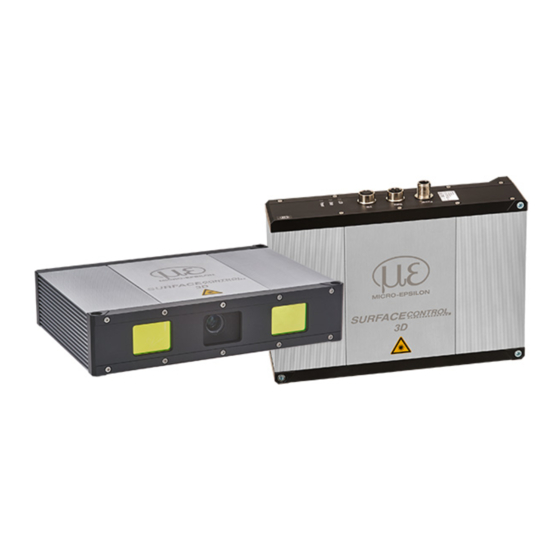
surfaceCONTROL 3D 32xx
Assembly Instructions
surfaceCONTROL
3D SC3200 / SC3210
Page 1
Advertisement
Table of Contents

Related Manuals for MICRO-EPSILON surfaceCONTROL 3D SC3200


Summary of Contents for MICRO-EPSILON surfaceCONTROL 3D SC3200
- Page 1 Assembly Instructions surfaceCONTROL 3D SC3200 / SC3210 Warnings Do not look directly into the light source of the sensor. > Risk of injury, damage to the eyes and skin Connect the power supply and the display/output device according to the safety regulations for electrical equipment.
-
Page 2: Proper Environment
Proper Environment - Protection class ƒ Sensor: IP67 (only applies in the case of connected output connectors and/or installed protective caps) Optical paths during operation are excluded from the protection class. Contamination of the paths causes impairment or failure of the function. The IP67 protection class is a specification that is limited to protection from dust and water. -
Page 3: Light Source
If both warning labels are covered over when the unit is installed, the user must ensure that supplementary labels are applied. You can find more information about the sensor in the operating instructions. They are online at: www.micro-epsilon.com/download/manuals/man--surfaceCONTROL-3D-32xx--en.pdf. surfaceCONTROL 3D 32xx Page 3... -
Page 4: Electrical Connections
Fig. 3 Pin assignment of the power supply connection The operating voltage is protected against polarity reversal. Use only shielded lines or original cables from the accessories program for the power supply connection or the outputs. Micro-Epsilon recommends the ECR3000-x shielded supply cable. surfaceCONTROL 3D 32xx Page 4... - Page 5 The multi-function connection is a 12-pin M12 round connector. The connecting line is intended to be up to 35 m long; however, the cable must be shielded at any length. Micro-Epsilon recommends using the PCR3000-x multi-function cable. surfaceCONTROL 3D 32xx...
- Page 6 Digital Signals The four digital connections of the multi-function interface provided can operate option- ally as inputs or outputs. They are configured using the software. All digital ports share a joint ground GND GPIO. External auxiliary power (max. 30 V) is required to use the outputs.
- Page 7 The outputs can optionally be assigned the internal signals below: Internal signal Description UserOutput0 Digital output signal that can be set via Genicam FrameTriggerWait Sensor is ready for next measurement FrameTriggerMissed (External) trigger was missed (sensor was not yet ready for measurement) FrameActive 3D measurement in sensor is active (start at exposure of first image, end at completion of data transmission via GigE)
- Page 8 Electrical Parameters of Digital Inputs, Multi-Function Connection The switching levels of the digital inputs are defined based on HTL logic: Low 0 … 3 V, High 11 … 24 V (up to 30 V permitted). IN, high Maximum input current is internally limited to 5 mA.
-
Page 9: Led Displays
LED Displays LED LED Meaning LED not active Constant green LED active LED State Meaning Flashing orange Initialization of sensor hardware Flashing green Initialization of communications interface Constant green Sensor is ready for operation Flashing Error during initialization of sensor hardware orange-green Communication with sensor possible Constant red... -
Page 10: Installation
Operation Commissioning The sensor may only be connected to peripherals when it does not carry power, that is, only when the operating voltage has been switched off. Mount the sensor according to the installation instructions. Connect the sensor to the Ethernet cable. Connect the Ethernet cable to the PC. - Page 11 Fig. 10 Result of camera images when aligned with crosshair You will find further details - in the respective operating instructions of the software provided by Micro-Epsilon, - or in the sensors operating instructions, chapter GenICam parameter description. surfaceCONTROL 3D 32xx...
-
Page 12: Further Information
MICRO-EPSILON with shipping costs prepaid. Any damage that is caused by improper handling, the use of force or by repairs or modifications by third parties is not covered by the liability for material defects.
Need help?
Do you have a question about the surfaceCONTROL 3D SC3200 and is the answer not in the manual?
Questions and answers