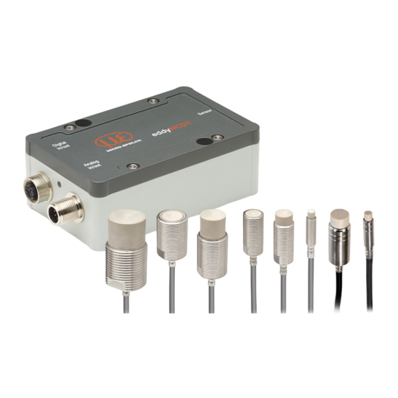
MICRO-EPSILON eddyNCDT 3060 Operating Instructions Manual
Sensors es-u1, es-s2, es-u3, es-s4
Hide thumbs
Also See for eddyNCDT 3060:
- Quick manual (25 pages) ,
- Operating instructions manual (66 pages) ,
- Quick manual (25 pages)
Table of Contents
Advertisement
Quick Links
Advertisement
Table of Contents

Related Manuals for MICRO-EPSILON eddyNCDT 3060


Summary of Contents for MICRO-EPSILON eddyNCDT 3060
- Page 1 Operating Instructions eddyNCDT 3060 eddyNCDT 3061 ES-U1 ES-S2 ES-U3 ES-S4...
- Page 2 Non-contact Compact Displacement Measuring System Based on Eddy Currents MICRO-EPSILON MESSTECHNIK GmbH & Co. KG Koenigbacher Str. 15 94496 Ortenburg / Germany Tel. +49 (0) 8542 / 168-0 Fax +49 (0) 8542 / 168-90 e-mail info@micro-epsilon.com www.micro-epsilon.com...
-
Page 3: Table Of Contents
Contents Safety ................................ 7 Symbols Used ..............................7 Warnings ................................7 Notes on CE Marking ............................8 Intended Use ..............................8 Proper Environment ............................9 Functional Principle, Technical Data ..................... 10 Field of Application ............................10 Measuring Principle ............................10 Structure of the Complete Measuring System .................... - Page 4 Electrical Connections ........................... 25 4.8.1 Connection Options ........................25 4.8.2 Pin Assignment ..........................26 4.8.3 Supply Voltage ..........................27 4.8.4 Analog Output, Displacement ..................... 27 4.8.5 Temperature and switching output....................28 4.8.5.1 General ............................28 4.8.5.2 Analog Output, Temperature ......................28 4.8.5.3 Switching Output for Limit Value ....................
- Page 5 System Settings ............................. 45 5.7.1 Language Selection........................45 5.7.2 Login, Change of the User Level ....................45 5.7.3 Password ............................46 5.7.4 Ethernet Settings .......................... 46 5.7.5 Import, Export ..........................47 Positioning the Target ............................ 48 Distance Measurements ..........................49 Elimination Errors ...........................
- Page 6 eddyNCDT 306x...
-
Page 7: Safety
Safety Safety System operation assumes knowledge of the operating instructions. Symbols Used The following symbols are used in this operating instructions. Indicates a hazardous situation which, if not avoided, may result in minor or CAUTION moderate injury. Indicates a situation that may result in property damage if not avoided. Indicates a user action. -
Page 8: Notes On Ce Marking
(EN) listed therein. The EU Declaration of Conformity is available to the responsible authorities according to EU Directive, articel 10, at: MICRO-EPSILON MESSTECHNIK GmbH & Co. KG Koenigbacher Str. 15 94496 Ortenburg / Germany The measuring system is designed for use in industrial environments and meets the requirements. -
Page 9: Proper Environment
Safety Proper Environment - Protection class: ƒ Sensor, sensor cable: IP 68 (plugged) ƒ Controller: IP 67 (plugged) - Temperature range: ƒ Operation: • Sensor, sensor cable: -20 ... +180 °C (-4 ... +356 °F), valid for sensor ES-U1 -20 ... +200 °C (-4 ... +392 °F), valid for standard sensors •... -
Page 10: Functional Principle, Technical Data
Functional Principle, Technical Data Functional Principle, Technical Data Field of Application The eddyNCDT 306x non-contact, compact displacement measuring systems are designed for industrial applications in production plants, for machine supervision and for measuring and testing in in-process quality assurance. Measuring Principle The eddyNCDT 306x (Non-Contacting Displacement Transducers) displacement measuring system operates without contact using eddy current technology. -
Page 11: Glossary, Analog Output Displacement
Functional Principle, Technical Data Glossary, Analog Output Displacement 10 V 20 mA 12 mA Displace- ment 4 mA Sensor Target Measuring range (MR) Start of measuring range Minimum distance between sensor front and measuring object, sensor specific Mid of measuring range End of measuring range (Start of measuring range + measuring range) Maxi- mum distance between sensor front and measuring object Measuring range... -
Page 12: Technical Data
Functional Principle, Technical Data Technical Data Sensor ES-U1 ES-S2 ES-U3 ES-S4 Measuring range 1 mm 2 mm 3 mm 4 mm Start of measuring range 0.1 mm 0.2 mm 0.3 mm 0.4 mm End of measuring range 1.1 mm 2.2 mm 3.3 mm 4.4 mm static (20 Hz) - Page 13 Functional Principle, Technical Data ES-U1 ES-S2 ES-U3 Sensor ES-S4 0 … 10 V (short circuit proof); 4 … 20 mA (load max. 500 Ohm) Analog output 2,4 g 11 g 12 g 30 g Weight sensors (without nuts) ca. 230 g controller 15 g / 6 ms in 3 axes, 2 directions and 1000 shocks each Shock (DIN-EN 60068-2-29)
-
Page 14: Delivery
Delivery Delivery Unpacking, Included in Delivery 1 Sensor incl. sensor cable 1 Controller 1 Test log 1 Quick manual 1 PC3/8-M12 (analog output/ power supply) 1 SCD2/4/RJ45 Ethernet adapter cable Carefully remove the components of the measuring system from the packaging and ensure that the goods are forwarded in such a way that no damage can occur. -
Page 15: Installation And Assembly
Installation and Assembly Installation and Assembly General No sharp or heavy objects should be allowed to affect the cable sheath of the sensor cable, the supply cable and the output cable. A damaged cable cannot be repaired. Tension on the cable is not permitted! 4.1.1 Model The eddyNCDT measuring system will be used with unshielded or shielded sensors. -
Page 16: Start Of Measuring Range
Installation and Assembly 4.1.2 Start of Measuring Range Sensor Target Measuring range (MR) Fig. 4 Start of measuring range (SMR), the minimum distance between sensor face and target For each sensor a minimum distance to the measuring object must be maintained. This avoids a measurement uncertainty due to the sensor pressing on the measuring object and mechanical damage to the sensor/target. -
Page 17: Installation Scenario Sensor
The sensors protrude beyond the metal holder. The installation scenario depicted is used for factory calibration of the sensors at Micro-Epsilon. The technical sensor data correspond to standard installation conditions. If you want to achieve the values indicated in the data sheet, we recom- mend to install the sensor in the same way as it was during calibration. -
Page 18: Flush Mounting
4.2.2 Flush Mounting Flush mounting does not correspond to factory calibration. Micro-Epsilon recommends to carry out at least a 3-point field linearization. Linearize the measuring system, if possible, when it is exactly arranged (in the same way as it will be arranged later during the measurement process). -
Page 19: Measurement Setup, Operating Multiple Sensors
Installation and Assembly Measurement Setup, Operating Multiple Sensors Sensors of the eddyNCDT 306x series cannot be synchronized. Observe the following installation information regarding the minimum distance between two sensors: - 3x sensor diameter distance between two unshielded sensors with equal carrier frequency (e. g. low frequency) - 1.5x sensor diameter distance between two shielded sensors with equal carrier frequency (e. -
Page 20: Dimensional Drawings Sensors
Installation and Assembly Dimensional Drawings Sensors (.13) (.79) ca. 100 (3.94) ca.26 (1.02) (.16) (.31) ca. 8 Cable length x ca. 36 (1.42) (.87) (.31) Fig. 9 Dimensional drawing sensors ES-U1-C-CAx/mB0, dimensions in mm (inches) 20 (.79) ca.100 (3.94) ca. 26 (1.02) 4 (.16) (.24) ca. - Page 21 Installation and Assembly (.24) 20 (.79) ca. 100 (3.94) 6 (.24) ca. 26 (1.02) (.39) ca. 8 Cable length x 31 (1.22) ca. 36 (1.42) (.31) Fig. 11 Dimensional drawing sensors ES-U3-C-CAx/mB0, dimensions in mm (inches) (.24) 20 (.79) ca.100 (3.94) ca.
-
Page 22: Sensor Cable
Installation and Assembly Sensor Cable Do not kink the cable - the minimum bending radius is 20 mm (static) or 40 mm (moved). Route the sensor cable in such a way that no sharp-edged or heavy objects can affect the cable sheath. Connect the sensor cable to the controller. -
Page 23: Dimensional Drawing Controller
Installation and Assembly Dimensional Drawing Controller The controller DT306x is installed in an aluminum casing. 127 (5.00) - The oscillator electronics feeds the sensor with a frequency 105 (4.13) and amplitude-stable AC voltage. - The demodulator electronics demodulates, linearizes and amplifies the distance dependent measuring signal. -
Page 24: Target Size
A successful calibration is a prerequisite to minimize linearity errors. In order to achieve an optimal result, Micro-Epsilon recommends a linearity calibration on the corresponding measuring object. A change of the measuring object size has significant effects on the quality of the measu- rement results. -
Page 25: Electrical Connections
Installation and Assembly Electrical Connections 4.8.1 Connection Options Power supply and signal output are provided via plug connectors on the front of the controller. Ethernet Controller EC-x/y Sensor PCx/8-M12 PS 2020 Ammeter/Voltmeter eddyNCDT 306x Page 25... -
Page 26: Pin Assignment
Installation and Assembly 4.8.2 Pin Assignment Wire color Signal PCx/8-M12 brown +24 VDC supply, polarity protection blue GND supply white (load min. 30 kOhm) displacement pink Fig. 16 Pin side 8-pin. housing plug displacement (load max. 500 Ohm) displacement Temperature and switching output 1 green / limit value 1 temp sensor... -
Page 27: Supply Voltage
Controller PCx/8-M12 Supply and not for drive units or similar sources of pulse interfe- 12 ... Color rence at the same time. MICRO-EPSILON recommends 32 VDC DT306x brown using an optional available power supply unit PS2020 for the controller. blue Ground Fig. -
Page 28: Temperature And Switching Output
Installation and Assembly 4.8.5 Temperature and switching output 4.8.5.1 General These functions are possible with the DT3061 controller. Depending on the programming, an output can be used as temperature or switching output. 4.8.5.2 Analog Output, Temperature The temperature output enables to output the controller or sensor temperature. This function is possible with the DT3061 controller. -
Page 29: Operation
Operation Operation Checking the Measuring System Setup 1) Is the sensor adjusted for the application (target material)? 2) Are the sensor, sensor cable length and controller aligned (type and serial number)? 3) Is the sensor connected? Are the cable connections tight? LED Controller LED State green orange... -
Page 30: Control Via Web Interface
Operation Control via Web Interface 5.3.1 Requirements The controller generates dynamic web pages, that contain the current settings of the controller and the peripherals. The operation is only possible as long as there is an Ethernet connection to the controller. You need a web browser that supports HTML5 (e. - Page 31 Operation Direct connection to PC Network PC with static IP PC with DHCP Controller with dynamic IP , PC with DHCP Connect the controller to a PC via a direct Ethernet connection (LAN). Connect the controller to a switch. Start the SensorFinder.exe Wait until Windows has establis- Enter the controller in the DHCP / register the program.
-
Page 32: Access Via Web Interface
Operation 5.3.2 Access via Web Interface Additional help functions (e.g. Settings) are available in the top navigation bar. All settings on the web page are implemented in the controller immediately. Parallel operation with web browser and Telnet com- mands is possible; the last setting applies. -
Page 33: Characteristics And Linearization
Operation Characteristics and Linearization 5.4.1 General Before the measurement, calibrate the measurement channel for the installation environment of the sensor and the measurement object, see Chap. 5.4.4. The distance points for the linearization types are defined by comparison standards or micrometers calibrati- on devices. -
Page 34: Scaling Measuring Range
Operation 5.4.3 Scaling Measuring Range Menu Settings > Characteristics/Linearization > Scale measuring range There are two ways to scale the measuring range of the eddyNCDT 306x: - by using the mouse function directly in the graphic - using the fields Current measuring range begin and Current measuring range end. Fig. -
Page 35: Calibration And Linearization
Operation 5.4.4 Calibration and Linearization 5.4.4.1 Offset Before a calibration is performed, the measuring device should 50 % 100 % Sensor Target Measuring range warm up for about 30 minutes. The system is linearized, the mechanical zero point in the installed state should be redefined. -
Page 36: 2-Point Linearization
Operation 5.4.4.2 2-Point Linearization 50 % 100 % Sensor Choose 2-point for linearization and the desired unit. Target Measuring range The system is linearized and should be adapted to the ambient condi- tions in the machine. Menu Settings > Characteristics/Linearization > Place the measurement object to the sensor in Carry out field linearization. -
Page 37: 3-Point Linearization
Operation 5.4.4.3 3-Point Linearization Menu Settings > Characteristics/Linearization > 50 % 100 % Carry out field linearization. Sensor Target Measuring range If the sensor or the measurement object is changed by the user, a calibration must be carried out before the measurement. Here, use the following if possible: Place the measurement object to the sensor in - the original sensor mounting,... -
Page 38: 5-Point Linearization
Operation 5.4.4.4 5-Point Linearization This function is available with controller DT3061. 50 % 100 % Sensor Menu Settings > Characteristics/Linearization > Target Measuring range Carry out field linearization. If the sensor or the measurement object is changed by the user, a calibration must be carried out before the measurement. -
Page 39: Manage Characteristics
Operation 5.4.5 Manage characteristics The menu Settings > Characteristics/Linearization > Manage characteristic enables the import/export of factory-set characteristics and field characteristics. In addition, the field characteristics can be deleted, renamed or overwritten. Importing the factory-set characteristics is possible only to a limited extent if these have been protected by the manufacturer. -
Page 40: Processing
Operation Processing 5.5.1 Hardware filter The Hardware filter parameter in the tab Settings > Processing influences the bandwidth of the analog low-pass filter. This affects the analog outputs and the digital output. No data rate reduction. Hardware filter 20 / 5,000 / 20,000 Hz 5.5.2 Sensor Temperature, Controller Temperature Tab Settings >... -
Page 41: Outputs
Operation Outputs 5.6.1 Displacement, analog Menu Settings > Outputs > Displacement, 100 % analog. Analog Default characteristic Max. output range: 4 mA ... 20 mA or 0 V ... 10 V output Output amplification ∆ I : 16 mA or ∆ U : 10 V;... -
Page 42: Temperature And Limit Value Outputs
Operation 5.6.2 Temperature and Limit Value Outputs 5.6.2.1 General These functions are possible with the DT3061 controller. Depending on the configuration, an output can be used as temperature or switching output. 5.6.2.2 Temperature Output Menu Settings > Outputs > Temperature Via the temperature outputs, the sensor and controller temperatures can be scaled and output as analog voltage. -
Page 43: Limit Output
Operation 5.6.2.3 Limit Output Threshold A (A) This function is available with controller DT3061. Menu Settings > Outputs > Limit value 1/2. The eddyNCDT 3061 can check the measurement result to adjustable limits. This means that threshold values can be monitored, impermissible toleran- ces detected and sorting criteria realized. - Page 44 Operation Hysteresis Thres- hold A Thres- hold B t < Hold time Fig. 32 Timing limit monitoring, event (E) < hold time, logic: positive Hysteresis Thres- hold A Thres- hold B Event Hold time Fig. 33 Timing limit monitoring, event (E) > hold time, logic: negative Duration of limit infringement Delay time t <...
-
Page 45: System Settings
Operation System Settings 5.7.1 Language Selection The web interface promotes the units millimeter (mm) when displaying measuring results. You can choose Chinese, German, English, Japanese or Korean in the web interface. You can also change the language in the menu bar. 5.7.2 Login, Change of the User Level Menu Settings >... -
Page 46: Password
Operation 5.7.3 Password Assigning passwords and the User level prevent unauthorized changes to controller settings. In the delivery state, no password is deposited in the controller. A firmware update will not change a custom password. After the controller has been configured, you should enable password protection. Change to the menu Settings >... -
Page 47: Import, Export
Operation 5.7.5 Import, Export Menu Settings > System settings > Manage settings. Here you can export all controller settings in a file or reimport them from a file. Controller e.g. hardware filter, limit value settings settings Ethernet e.g. IP address, subnet mask settings When importing settings, consider if you want to replace the current controller and/or Ethernet settings. -
Page 48: Positioning The Target
Operation Positioning the Target Position the target within the sensor measuring range. The value for the start of the measuring range (SMR) depends on the sensor. This value can be found in the technical data of the sensor, see Chap. 2.5. If the user restricts the measuring range, this possibly results in new values for SMR, MMR and EMR. -
Page 49: Distance Measurements
Operation Distance Measurements Switch to the Measurement menu. Click the Start measuring button. Statistic values are calculated in the web interface. Clicking onto the start /stop measuring button starts/stops the calculation. At the beginning of measurement, the statistic values are reset. During a measurement, the statistic values are updated with each new package received by the controller. -
Page 50: Elimination Errors
Elimination Errors Elimination Errors Error Cause and solution Output signal in positive or negative saturation, - Cable and/or sensor not connected. depends on the scaling of the analog output. - Sensor has open loop. - Cable is defective. Please note the remarks in the web interface. Replace cable and/or sensor. -
Page 51: Liability For Material Defects
The liability for material defects is 12 months from delivery. Within this period, defective parts, except for wearing parts, will be repaired or replaced free of charge, if the device is returned to MICRO-EPSILON with shipping costs prepaid. Any damage that is caused by improper handling, the use of force or by repairs or modifications by third parties is not covered by the liability for material defects. -
Page 52: Appendix
Appendix | Optional Accessories Appendix Optional Accessories PS2020 Power supply unit Input: 100-240 VAC Output: 24 VDC / 2.5 A Mounting onto symmetrical standard rail 35 mm x 7.5 mm DIN 50022 MC25D(01) Micrometer calibration unit Setting range: 0-2.5 mm, with digital position reading and adjustable zero, for sensors type ES04-ES2 resp. - Page 53 Appendix | Optional Accessories PCx/8-M12 Supply and signal cable 8-pin with M12 connector Standard length: 3 m Optionally available: 3 / 10 / 15 m 10 m as drag-chain suitable variant eddyNCDT 306x Page 53...
-
Page 54: A 2 Model Designation Sensor
Appendix | Model Designation Sensor Model Designation Sensor A = mini Eddy Measuring range S = male connector B = normal Sensor 1 / 2 / 3 / 4 mm C = integrated cable Cable length [m] C = large Option S = shielded C = cylindric... - Page 56 MICRO-EPSILON MESSTECHNIK GmbH & Co. KG X9751385-A011119SWE Koenigbacher Str. 15 · 94496 Ortenburg / Germany MICRO-EPSILON MESSTECHNIK Tel. +49 (0) 8542 / 168-0 · Fax +49 (0) 8542 / 168-90 *X9751385-A01* info@micro-epsilon.com · www.micro-epsilon.com...
Need help?
Do you have a question about the eddyNCDT 3060 and is the answer not in the manual?
Questions and answers