Table of Contents
Advertisement
Quick Links
Operation & Maintenance Manual
AM Series
Natural Gas and Propane Gas Modulating
Condensing Boilers and Water Heaters
Other documents for this product include:
TAG-0072 GF-146-E Electrical Power Guide
TAG-0073 GF-146-G Gas Supply Guide
TAG-0074 GF-146-P Piping Application Guide
TAG-0075 GF-146-V Venting Guide
Applies to serial numbers:
From 18170091 and up.
Disclaimer
The information contained in this manual is subject to change without notice
from AERCO International, Inc. AERCO makes no warranty of any kind with
respect to this material, including, but not limited to, implied warranties of
merchantability and fitness for a particular application. AERCO International is
not liable for errors appearing in this manual, not for incidental or consequential
damages occurring in connection with the furnishing, performance, or use of
these materials
OMM-0100_0F
• GF-146 • 11/15/2019
© 2019 AERCO
Advertisement
Table of Contents

Subscribe to Our Youtube Channel
Related Manuals for Watts Aerco TAG-0072 GF-146-E


Summary of Contents for Watts Aerco TAG-0072 GF-146-E
- Page 1 Operation & Maintenance Manual AM Series Natural Gas and Propane Gas Modulating Condensing Boilers and Water Heaters Other documents for this product include: TAG-0072 GF-146-E Electrical Power Guide TAG-0073 GF-146-G Gas Supply Guide TAG-0074 GF-146-P Piping Application Guide TAG-0075 GF-146-V Venting Guide Applies to serial numbers: From 18170091 and up.
-
Page 2: Table Of Contents
AM Series Boiler & Water Heater User Manual TABLE OF CONTENTS Table of Contents FOREWORD ........................6 SECTION 1: GENERAL INFORMATION ................7 1.1 WARNINGS & CAUTIONS ..........................7 1.2 EMERGENCY SHUTDOWN ........................10 SECTION 2: FUNCTIONAL OVERVIEW ................11 2.1 INTRODUCTION ............................11 2.1.1 AM Water Heaters and Boilers .......................... - Page 3 AM Series Boiler & Water Heater User Manual TABLE OF CONTENTS 4.4 FREEZE PROTECTION ..........................46 4.5 FLOOR RADIANT HEATING SYSTEMS - BOILERS ................. 46 4.6 PIPING COMPONENTS - BOILERS ......................46 4.7 PIPING COMPONENTS – WATER HEATERS ................... 47 4.8 SAFETY RELIEF VALVE ..........................
- Page 4 AM Series Boiler & Water Heater User Manual TABLE OF CONTENTS 6.5.23 Multi-Venting Vertical Terminations ........................83 SECTION 7: INSTALLATION – NATURAL GAS ..............85 7.1 GAS SUPPLY PIPING ..........................85 7.2 CONNECTION OF GAS SUPPLY PIPING ....................85 7.3 NATURAL GAS PIPE SIZING ........................87 7.4 NATURAL GAS SUPPLY PRESSURE REQUIREMENTS .................
- Page 5 AM Series Boiler & Water Heater User Manual TABLE OF CONTENTS 9.20 DIAGNOSTICS – BLOCKING (ERR) ERRORS ..................119 9.21 BLOCKED FLUE PRESSURE SWITCH ....................121 9.22 UNIT SHUT-DOWN ..........................122 SECTION 10: MAINTENANCE ..................124 10.1 CHECKING FOR GAS LEAKS ........................ 125 10.2 FLUE AND AIR INLET PIPING INSPECTION ..................
-
Page 6: Foreword
AM Series Boiler & Water Heater User Manual FORWARD FOREWORD The Advanced Modular (AM) Series represents the latest in high efficiency, condensing boiler and water heater technology. The AM Series has a unique modular design that provides exceptional reliability, serviceability, and fuel savings from 399 to 1000 MBTU. Each unit is comprised of between two and four independent thermal modules firing up to 250 MBTU each at 5:1 individual turndown. -
Page 7: General Information
AM Series Boiler & Water Heater User Manual CHAPTER 1: GENERAL INFORMATION SECTION 1: GENERAL INFORMATION 1.1 Warnings & Cautions In addition to all the requirements included in this AERCO Instruction Manual, the installation of units MUST conform with local building codes, or, in the absence of local codes, ANSI Z223.1 (National Fuel Gas Code Publication No. - Page 8 AM Series Boiler & Water Heater User Manual CHAPTER 1: GENERAL INFORMATION NOTE: When calling or writing about the boiler, have the unit model and serial number as seen on the unit rating plate. CAUTION! Do not use petroleum-based cleaning or sealing compounds in the boiler system. Gaskets and seals in the system may be damaged.
- Page 9 AM Series Boiler & Water Heater User Manual CHAPTER 1: GENERAL INFORMATION OFF. OFF. OMM-0100_E • GF-146 • 11/15/2019 Technical Support • (800) 526-0288 • Mon-Fri, 8 am - 5 pm EST Page 9 of 170...
-
Page 10: Emergency Shutdown
AM Series Boiler & Water Heater User Manual CHAPTER 1: GENERAL INFORMATION 1.2 Emergency Shutdown If overheating occurs or the gas supply fails to shut off, close the manual gas shutoff valve (Figure 1-1) located external to the unit. NOTE: The Installer must identify and indicate the location of the emergency shutdown manual gas valve to operating personnel. -
Page 11: Functional Overview
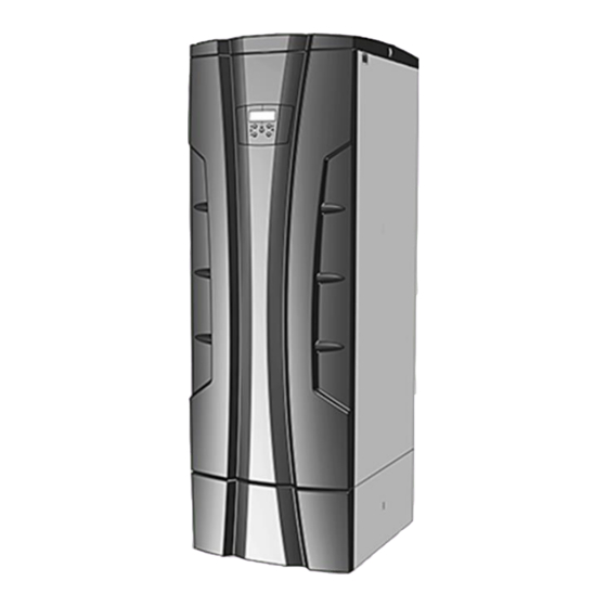
AM Series Boiler & Water Heater User Manual CHAPTER 2: FUNCTIONAL OVERVIEW SECTION 2: FUNCTIONAL OVERVIEW 2.1 INTRODUCTION 2.1.1 AM Water Heaters and Boilers Figure 2-1 shows the exterior appearance of the AM Series of boilers and water heaters. The AM Series comes in four functionally sized models;... -
Page 12: Intended Use - Boilers
AM Series Boiler & Water Heater User Manual CHAPTER 2: FUNCTIONAL OVERVIEW 2.2 Intended Use – Boilers The gas-fired condensing AM Series boilers are designed to be used in central heating systems. Any other use is prohibited. Heat is always guaranteed for the production of domestic hot water since it is given priority over space heating demands. -
Page 13: Am Series Functional Schematics
AM Series Boiler & Water Heater User Manual CHAPTER 2: FUNCTIONAL OVERVIEW 2.5 AM Series Functional Schematics 2.5.1 AM 399 / 500 Functional Schematic Figure 2-3: 399 / 500 (Boiler & Water Heater) Functional Schematic OMM-0100_E • GF-146 • 11/15/2019 Technical Support •... -
Page 14: Am 750 Functional Schematic
AM Series Boiler & Water Heater User Manual CHAPTER 2: FUNCTIONAL OVERVIEW 2.5.2 AM 750 Functional Schematic Figure 2-4: 750 (Boiler & Water Heater) Functional Schematic OMM-0100_E • GF-146 • 11/15/2019 Technical Support • (800) 526-0288 • Mon-Fri, 8 am - 5 pm EST Page 14 of 170... -
Page 15: Am 1000 Functional Schematic
AM Series Boiler & Water Heater User Manual CHAPTER 2: FUNCTIONAL OVERVIEW 2.5.3 AM 1000 Functional Schematic Figure 2-5: AM 1000 (Boiler & Water Heater) Functional Schematic OMM-0100_E • GF-146 • 11/15/2019 Technical Support • (800) 526-0288 • Mon-Fri, 8 am - 5 pm EST Page 15 of 170... -
Page 16: Amr Functional Schematic
AM Series Boiler & Water Heater User Manual CHAPTER 2: FUNCTIONAL OVERVIEW 2.5.4 AMR Functional Schematic MIXED BUILDING RECIRCULATION AND MAKEUP WATER RETURN LWCO (LOW WATER CUT-OFF) HOT WATER OUTLET GAS INLET BUFFER TANK RECIRCULATION RECIRCULATION LOOP PIPING LOOP PUMP HOT WATER OUTLET (FROM AM HEAT AM HEAT... -
Page 17: Main Components
AM Series Boiler & Water Heater User Manual CHAPTER 2: FUNCTIONAL OVERVIEW 2.6 Main Components 2.6.1 Burner Figure 2-7: Burner Main Components OMM-0100_E • GF-146 • 11/15/2019 Technical Support • (800) 526-0288 • Mon-Fri, 8 am - 5 pm EST Page 17 of 170... - Page 18 AM Series Boiler & Water Heater User Manual CHAPTER 2: FUNCTIONAL OVERVIEW Figure 2-8: Burner Main Components OMM-0100_E • GF-146 • 11/15/2019 Technical Support • (800) 526-0288 • Mon-Fri, 8 am - 5 pm EST Page 18 of 170...
-
Page 19: Am Series 199 And 250 Main Components
AM Series Boiler & Water Heater User Manual CHAPTER 2: FUNCTIONAL OVERVIEW 2.6.2 AM Series 199 and 250 Main Components Figure 2-9: AM Series 199 and 250 Main Components OMM-0100_E • GF-146 • 11/15/2019 Technical Support • (800) 526-0288 • Mon-Fri, 8 am - 5 pm EST Page 19 of 170... - Page 20 AM Series Boiler & Water Heater User Manual CHAPTER 2: FUNCTIONAL OVERVIEW Figure 2-10: AM Series 199 and 250 Main Components OMM-0100_E • GF-146 • 11/15/2019 Technical Support • (800) 526-0288 • Mon-Fri, 8 am - 5 pm EST Page 20 of 170...
- Page 21 AM Series Boiler & Water Heater User Manual CHAPTER 2: FUNCTIONAL OVERVIEW Figure 2-11: AM Series 199 and 250 Main Components OMM-0100_E • GF-146 • 11/15/2019 Technical Support • (800) 526-0288 • Mon-Fri, 8 am - 5 pm EST Page 21 of 170...
-
Page 22: Am Series 399 And 500 Main Components
AM Series Boiler & Water Heater User Manual CHAPTER 2: FUNCTIONAL OVERVIEW 2.6.3 AM Series 399 and 500 Main Components Figure 2-12: AM Series 399 and 500 Main Components OMM-0100_E • GF-146 • 11/15/2019 Technical Support • (800) 526-0288 • Mon-Fri, 8 am - 5 pm EST Page 22 of 170... - Page 23 AM Series Boiler & Water Heater User Manual CHAPTER 2: FUNCTIONAL OVERVIEW Figure 2-13: AM Series 399 and 500 Main Components OMM-0100_E • GF-146 • 11/15/2019 Technical Support • (800) 526-0288 • Mon-Fri, 8 am - 5 pm EST Page 23 of 170...
- Page 24 AM Series Boiler & Water Heater User Manual CHAPTER 2: FUNCTIONAL OVERVIEW Figure 2-14: AM Series 399 and 500 Main Components OMM-0100_E • GF-146 • 11/15/2019 Technical Support • (800) 526-0288 • Mon-Fri, 8 am - 5 pm EST Page 24 of 170...
-
Page 25: Am Series 750 And 1000 Main Components
AM Series Boiler & Water Heater User Manual CHAPTER 2: FUNCTIONAL OVERVIEW 2.6.4 AM Series 750 and 1000 Main Components Figure 2-15: AM Series 750 and 1000 Main Components OMM-0100_E • GF-146 • 11/15/2019 Technical Support • (800) 526-0288 • Mon-Fri, 8 am - 5 pm EST Page 25 of 170... - Page 26 AM Series Boiler & Water Heater User Manual CHAPTER 2: FUNCTIONAL OVERVIEW Figure 2-16: AM Series 750 and 1000 Main Components OMM-0100_E • GF-146 • 11/15/2019 Technical Support • (800) 526-0288 • Mon-Fri, 8 am - 5 pm EST Page 26 of 170...
- Page 27 AM Series Boiler & Water Heater User Manual CHAPTER 2: FUNCTIONAL OVERVIEW Figure 2-17: AM Series 750 and 1000 Main Components OMM-0100_E • GF-146 • 11/15/2019 Technical Support • (800) 526-0288 • Mon-Fri, 8 am - 5 pm EST Page 27 of 170...
- Page 28 AM Series Boiler & Water Heater User Manual CHAPTER 2: FUNCTIONAL OVERVIEW (This page intentionally blank) OMM-0100_E • GF-146 • 11/15/2019 Technical Support • (800) 526-0288 • Mon-Fri, 8 am - 5 pm EST Page 28 of 170...
-
Page 29: Installation - Site
AM Series Boiler & Water Heater User Manual CHAPTER 3: INSTALLATION – SITE SECTION 3: INSTALLATION – SITE 3.1 Choosing the Installation Location This section describes the general installation considerations for the AM Series units. WARNING! Provisions for combustion air and ventilation of the boiler room are always required, regardless whether the combustion air is taken from the outside (Direct Vent, sealed combustion) or inside (room air for combustion). -
Page 30: Boiler And Water Heater Installation Location Factors
AM Series Boiler & Water Heater User Manual CHAPTER 3: INSTALLATION – SITE WARNING! Do not store or use gasoline or other flammable vapors or liquids in the vicinity of this or any other appliance. WHAT TO DO IF YOU SMELL GAS: •... -
Page 31: Safety Concerns
AM Series Boiler & Water Heater User Manual CHAPTER 3: INSTALLATION – SITE 3.3 Safety Concerns WARNING! Do not store any flammable materials or liquids in the immediate vicinity of the boiler. 3.4 Closet and Alcove Installation AM boilers or water heaters are not approved for installation in a closet or in an alcove site. 3.5 Clearances for Installation and Servicing Figures 3-1, 3-2 and 3-3 show the minimum clearances required for installation and servicing. -
Page 32: Clearances To Combustible Material
AM Series Boiler & Water Heater User Manual CHAPTER 3: INSTALLATION – SITE Figure 3-3: AMR Option - Recommended Minimum Service Clearances NOTE: Service clearances are minimum required clearances for ease of access, but larger service clearances are always preferred. 3.6 Clearances to Combustible Material This unit may be installed directly onto a floor of combustible material with the following clearances:... -
Page 33: Vent And Combustion Air Piping
AM Series Boiler & Water Heater User Manual CHAPTER 3: INSTALLATION – SITE 3.7 Vent and Combustion Air Piping This boiler requires a special vent system, designed for pressurized venting. The boiler is to be configured for either direct vent installation or for installation using room combustion air. -
Page 34: Transporting A Standard Am Unit
AM Series Boiler & Water Heater User Manual CHAPTER 3: INSTALLATION – SITE 3.10.1 Transporting a Standard AM Unit Transport a standard AM boiler or water heater to its installation location as follows. Standard Transporting a AM Water Heater or Boiler Remove the lower cover “A”... - Page 35 AM Series Boiler & Water Heater User Manual CHAPTER 3: INSTALLATION – SITE Standard Transporting a AM Water Heater or Boiler – Continued Using the appropriate lifting equipment, hoist the unit from the wood pallet. The weight of each models are as follows: Model Weight (lbs.) WARNING!
-
Page 36: Transporting An Amr Water Heater
AM Series Boiler & Water Heater User Manual CHAPTER 3: INSTALLATION – SITE 3.10.2 Transporting an AMR Water Heater For an AM water heater with the rapid recovery option, the buffer tank is shipped separately from the main unit and must be assembled after main unit installation. The buffer tank should only be assembled to the unit after the water heater has been transported, located, positioned installed in its final operating position. -
Page 37: Amr Buffer Tank Installation
AM Series Boiler & Water Heater User Manual CHAPTER 3: INSTALLATION – SITE 3.11 AMR Buffer Tank Installation 3.11.1 AMR Buffer Tank Installation Kits If you are installing an AMR series unit (with rapid recovery option), the buffer tank is shipped as a separate item and installed only after the main water heater unit is in its final installation location and position. -
Page 38: Amr Buffer Tank Components
AM Series Boiler & Water Heater User Manual CHAPTER 3: INSTALLATION – SITE 39209 – BASE EXTENSION 97084 - FLEX HOSE 56034 - 3/8-16 LOCKNUT 121699 - BOLT 3/8-16 53050 - FLAT WASHER, 3/8 90046-3 - NIPPLE, 2x3L 93499 - REDUCING COUPLING, 2-1/2 x 2 Figure 3-9: Buffer Tank Installation Parts Illustration 3.12 AMR Buffer Tank Components The following components are provided and must be installed on the buffer tank during... -
Page 39: Removing The Amr Bracing Plate
AM Series Boiler & Water Heater User Manual CHAPTER 3: INSTALLATION – SITE 3.14 Removing the AMR Bracing Plate The AMR bracing plate MUST be removed prior to tank installation while the remaining struts, required for shipping, may be left in place or removed. After AMR unit is placed, remove the screws affixing the bracing plate covering the lower rear section of the AMR water heater, as shown in Figure 3-11. - Page 40 AM Series Boiler & Water Heater User Manual CHAPTER 3: INSTALLATION – SITE Installing the 80-Gallon Tank for All AMR Models - Continued Install the thermowell (P/N 49263) into the lower port on tank (see Figure 3-13) with pipe dope, then put heat conducting compound (P/N 122848) inside the thermowell. Put the temperature sensor probe through the cord grip (P/N 62005) and then insert the sensor fully into the thermowell (see Figure 3-13).
-
Page 41: Amr 119-Gallon Buffer Tank Installation
AM Series Boiler & Water Heater User Manual CHAPTER 3: INSTALLATION – SITE 3.16 AMR 119-Gallon Buffer Tank Installation Installing the AMR 119-Gallon Buffer Tank WARNING! Affixing the base extension to the base is required for 119-gallon tank installation. Remove the two tank clamps from REAR of main base and relocate them to base extension (P/N 39209) using the existing hardware (Figure 3-14). - Page 42 AM Series Boiler & Water Heater User Manual CHAPTER 3: INSTALLATION – SITE Installing the 119-Gallon Tank - Continued Install the thermowell (P/N 49263) into the lower port on tank (see Figure 3-16) with pipe dope, then put heat conducting compound (P/N 122848) inside the thermowell. Put the temperature sensor probe through the cord grip (P/N 62005) and then insert the sensor fully into the thermowell (see Figure 3-16).
-
Page 43: Am Series Supply And Return Piping Dimensions
AM Series Boiler & Water Heater User Manual CHAPTER 3: INSTALLATION – SITE 3.17 AM Series Supply and Return Piping Dimensions 3.17.1 Standard AM Supply and Return Piping Dimensions Standard connections and dimensions for all AM Series units are shown in Figure 3-17. Models AM 399/500 Models... -
Page 44: Amr Supply And Return Piping Dimensions
AM Series Boiler & Water Heater User Manual CHAPTER 3: INSTALLATION – SITE 3.17.2 AMR Supply and Return Piping Dimensions Connections and dimensions for AM Series water heaters with the Rapid Recovery option are shown in Figure 3-18. COLD WATER INLET HOT WATER OUTLET Gallon Tank... -
Page 45: Installation - Piping
AM Series Boiler & Water Heater User Manual CHAPTER 4: INSTALLATION – PIPING SECTION 4: INSTALLATION – PIPING 4.1 Water Inlet and Outlet Piping When connecting the hot water outlet and cold water inlet to building piping, first make sure the threads are thoroughly clean. -
Page 46: Freeze Protection
AM Series Boiler & Water Heater User Manual CHAPTER 4: INSTALLATION – PIPING gas ignition system components are protected from water (dripping, spraying, etc.), during appliance operation for basic service of circulator replacement, valves, and others. 4.3.1 Low water cutoff device On a boiler installed above radiation level, some states and local codes require a low water cutoff device at the time of installation. -
Page 47: Piping Components - Water Heaters
AM Series Boiler & Water Heater User Manual CHAPTER 4: INSTALLATION – PIPING • Indirect water heater circulating pump: Field supplied. The pump MUST be sized to meet the specified flow requirements. Consult the indirect water heater operating guide to determine flow characteristics for the selected product used. -
Page 48: Safety Relief Valve
AM Series Boiler & Water Heater User Manual CHAPTER 4: INSTALLATION – PIPING • Connect the cold water supply to the inlet side of the water heater. • Connect the hot water supply to the outlet side of the water heater. •... -
Page 49: Low Water Cutoff (Lwco)
AM Series Boiler & Water Heater User Manual CHAPTER 4: INSTALLATION – PIPING SAFETY RELIEF VALVE & T&P GAUGE SAFETY RELIEF VALVE & T&P GAUGE HOT WATER SUPPLY OUTLET SAFETY RELIEF RELIEF VALVE DISCHARGE VALVE & T&P GAUGE PIPING (one for each valve and piped to within 18”... -
Page 50: Expansion Tank And Makeup Water
AM Series Boiler & Water Heater User Manual CHAPTER 4: INSTALLATION – PIPING 4.10 Expansion Tank and Makeup Water Install an expansion tank. Ensure the expansion tank is properly sized for the boiler volume and the system volume, temperature and pressure. CAUTION! Undersized expansion tanks will cause system water to be lost through the pressure relief valve and cause additional makeup water to be added to the system. - Page 51 AM Series Boiler & Water Heater User Manual CHAPTER 4: INSTALLATION – PIPING and may require a larger circulating pump, and a revised temperature rise specification based on the water chemistry of the water to be heated. Size your water system according to the following hardness guidelines to prevent scaling of the heat exchanger.
-
Page 52: Domestic Hot Water System Piping With Direct Water Heater: Water Heaters
AM Series Boiler & Water Heater User Manual CHAPTER 4: INSTALLATION – PIPING Figure 4-5: AM Boiler Piping Example (Models AM750/1000 Shown) 4.12 Domestic Hot Water System Piping with Direct Water Heater: Water Heaters See Figure 4-5, for recommended piping for the AM Series water heater. Refer to Figure 5-3 to wire the water heater pump. -
Page 53: Scalding - Water Heaters
AM Series Boiler & Water Heater User Manual CHAPTER 4: INSTALLATION – PIPING 4.13 Scalding – Water Heaters This water heater can deliver scalding temperature water at any faucet in the system. Be careful whenever using hot water to avoid scalding injury. Certain appliances such as dishwashers and automatic clothes washers may require increased temperature water. - Page 54 AM Series Boiler & Water Heater User Manual CHAPTER 4: INSTALLATION – PIPING Figure 4-7: AM Water Heater Piping Example (Models AM 750W/1000W Shown) OMM-0100_E • GF-146 • 11/15/2019 Technical Support • (800) 526-0288 • Mon-Fri, 8 am - 5 pm EST Page 54 of 170...
-
Page 55: Condensate Disposal
AM Series Boiler & Water Heater User Manual CHAPTER 4: INSTALLATION – PIPING 4.14 Condensate Disposal WARNING! The condensate trap (Fig. 4-8, item “B”) MUST be filled with water or combustion gases will enter the room. The condensate neutralizer tank must be installed into the unit exactly as shown in Figure 4-8. - Page 56 AM Series Boiler & Water Heater User Manual CHAPTER 4: INSTALLATION – PIPING E = Condensate Drain Pipe F = Floor Drain or Drain Pan Figure 4-9: Condensate Tank Draining A condensate removal pump is required if the boiler is below the drain. When installing a condensate pump, select one approved for use with condensing boilers and furnaces.
-
Page 57: Installation - Electrical
AM Series Boiler & Water Heater User Manual CHAPTER 5: INSTALLATION – ELECTRICAL SECTION 5: INSTALLATION – ELECTRICAL 5.1 Electrical Connections – Boilers and Water Heaters 5.1.1 Power Supply Cable Connection - Boilers and Water Heaters Provide and install a fused disconnect or service switch (15 amp recommended) as required by prevailing codes. -
Page 58: Connecting Units In Cascade - Boilers And Water Heaters
AM Series Boiler & Water Heater User Manual CHAPTER 5: INSTALLATION – ELECTRICAL 24VDC VOLTAGE TERMINALS 120VAC VOLTAGE TERMINALS Jumper (Field supplied) or aquastat if used (Field supplied) Figure 5-3: Water Heater Electrical Junction Box Connections (with Direct Storage Tank) 5.1.2 Connecting Units in Cascade - Boilers and Water Heaters Boilers or water heaters may be combined in a cascading system using the optional Cascade Sequencer (P/N 62110095). -
Page 59: Modbus Interface Connections - Boilers And Water Heaters
AM Series Boiler & Water Heater User Manual CHAPTER 5: INSTALLATION – ELECTRICAL Figure 5-4: 0-10 VDC Analog Input Algorithm 5.1.4 MODBUS Interface Connections – Boilers and Water Heaters The AM Series models 500, 750 and 1000 are factory supplied with a Communications Module (the 399 model can be equipped with one as an option). -
Page 60: Electrical Connections - Boilers Only
AM Series Boiler & Water Heater User Manual CHAPTER 5: INSTALLATION – ELECTRICAL 5.2 Electrical Connections – Boilers Only 5.2.1 Enable/Disable - Boilers For remote enabling/disabling of a boiler, follow the instructions below. Wiring an ON/OFF Control to the Boiler Remove the boiler front cover according to the instructions in Section 10.14. -
Page 61: Indirect Water Heater Connection - Boilers
AM Series Boiler & Water Heater User Manual CHAPTER 5: INSTALLATION – ELECTRICAL To connect an outdoor sensor to the boiler, perform the following: Connecting the Outdoor Temperature Sensor to the Boiler Remove the boiler front cover according to the instructions in Section 10.14. Connect the leads of a two conductor cable (with a minimum cross section of #18 AWG) to the outdoor temperature sensor and run the cable to the boiler electrical junction box. -
Page 62: Electrical Connections - Water Heaters Only
AM Series Boiler & Water Heater User Manual CHAPTER 5: INSTALLATION – ELECTRICAL • If parameter 2067 is set to “0”, the boiler will load the indirect water heater for the time set in parameter 2063 and, after that, heating will take place for the same amount of time. •... - Page 63 AM Series Boiler & Water Heater User Manual CHAPTER 5: INSTALLATION – ELECTRICAL Figure 5-6: AMR Recirculation Pump, Pump Relay, and LWCO Wiring (Other Wiring Not Shown for Clarity) OMM-0100_E • GF-146 • 11/15/2019 Technical Support • (800) 526-0288 • Mon-Fri, 8 am - 5 pm EST Page 63 of 170...
- Page 64 AM Series Boiler & Water Heater User Manual CHAPTER 5: INSTALLATION – ELECTRICAL (This page intentionally blank) OMM-0100_E • GF-146 • 11/15/2019 Technical Support • (800) 526-0288 • Mon-Fri, 8 am - 5 pm EST Page 64 of 170...
-
Page 65: Installation - Venting And Combustion Air Piping
AM Series Boiler & Water Heater User Manual CHAPTER 6: INSTALL – VENT & COMBUSTION AIR PIPING SECTION 6: INSTALLATION – VENTING AND COMBUSTION AIR PIPING WARNING! DO NOT connect this gas appliance, or any other appliance using a positive venting pressure, in a common vent system with other equipment! Failure to comply with this WARNING could result in the accumulation of carbon monoxide gas which can cause severe personal injury or death. -
Page 66: General Venting And Air Piping Systems
AM Series Boiler & Water Heater User Manual CHAPTER 6: INSTALL – VENT & COMBUSTION AIR PIPING 6.2 General Venting and Air Piping Systems The AM Series of boilers and water heaters requires a special vent system, designed for pressurized venting. The unit is to be used for either direct vent installation or for installation using room combustion air. - Page 67 AM Series Boiler & Water Heater User Manual CHAPTER 6: INSTALL – VENT & COMBUSTION AIR PIPING Figure 6-1: Acceptable Vent/Air Piping Methods for AM Series Units OMM-0100_E • GF-146 • 11/15/2019 Technical Support • (800) 526-0288 • Mon-Fri, 8 am - 5 pm EST Page 67 of 170...
-
Page 68: Min/Max Allowable Combustion Air And Vent Piping Lengths
AM Series Boiler & Water Heater User Manual CHAPTER 6: INSTALL – VENT & COMBUSTION AIR PIPING 6.3 Min/Max Allowable Combustion Air and Vent Piping Lengths • The maximum length of the two pipes vent system is 120 equivalent feet (air intake plus flue exhaust). -
Page 69: Installations Requiring High Temperature Venting
AM Series Boiler & Water Heater User Manual CHAPTER 6: INSTALL – VENT & COMBUSTION AIR PIPING Polypropylene and stainless steel pipe may require an adaptor (not provided) to transition between the air inlet connection on the appliance and the air inlet pipe. Contact the vent manufacturer for a suitable adaptor. -
Page 70: Sealing Of Pvc, Cpvc Or Abs
AM Series Boiler & Water Heater User Manual CHAPTER 6: INSTALL – VENT & COMBUSTION AIR PIPING 6.5.2 Sealing of PVC or CPVC The PVC or CPVC should be cleaned and sealed with the pipe manufacturer’s recommended solvents and standard commercial pipe cement for the material used. The PVC or CPVC should use a silicone sealant to ensure a proper seal at the appliance connection and the air inlet cap connection. -
Page 71: Air Intake And Vent Starter Pieces
AM Series Boiler & Water Heater User Manual CHAPTER 6: INSTALL – VENT & COMBUSTION AIR PIPING 6.5.4 Air Intake and Vent Starter Pieces Venting must be supported per guidelines listed in the National Mechanical Code, Section 305, Table 305.4 or as local codes dictate. Figure 6-2 shows how the air intake and vent outlet adapters are assembled. -
Page 72: Single Pipe Venting (Room Air Combustion)
AM Series Boiler & Water Heater User Manual CHAPTER 6: INSTALL – VENT & COMBUSTION AIR PIPING Figure 6-3: Air Intake and Vent Connection Correctly Installed Installation must comply with local requirements and with the National Fuel Gas Code, ANSI Z223.1 for U.S. -
Page 73: Determining Vent Termination Location
AM Series Boiler & Water Heater User Manual CHAPTER 6: INSTALL – VENT & COMBUSTION AIR PIPING 6.5.6 Determining Vent Termination Location Locate the vent termination using the following guidelines: The total length of piping for vent must not exceed the limits given in Section 6.3. -
Page 74: Sidewall Termination - Two Pipes
AM Series Boiler & Water Heater User Manual CHAPTER 6: INSTALL – VENT & COMBUSTION AIR PIPING NOTE Minimum clearances to grade may be higher depending on snow line. Figure 6-4: Vent Locations and Clearances for Direct Venting 6.5.7 Sidewall Termination - Two pipes Installation must comply with local requirements and with the National Fuel Gas Code, ANSI Z223.1 for U.S. -
Page 75: Combustion Air And Ventilation Openings
AM Series Boiler & Water Heater User Manual CHAPTER 6: INSTALL – VENT & COMBUSTION AIR PIPING 6.5.8 Combustion Air and Ventilation Openings Outdoor combustion air shall be provided through opening(s) to the outdoors. WARNING! Make sure that combustion air and ventilation openings are sufficiently sized and no reduction or closure of openings takes place. -
Page 76: Sidewall Termination And Fittings
AM Series Boiler & Water Heater User Manual CHAPTER 6: INSTALL – VENT & COMBUSTION AIR PIPING Figure 6-6: Separate Air Intake and Vent Pipes Sidewall Termination 6.5.12 Sidewall Termination and Fittings Ensure the following when installing through sidewalls: • The air termination coupling must be oriented at least 12 inches above grade or snow line as shown in Figure 6-5. -
Page 77: Sidewall Termination - Concentric Vent
AM Series Boiler & Water Heater User Manual CHAPTER 6: INSTALL – VENT & COMBUSTION AIR PIPING Figure 6-7: Two-Pipe Multi-Unit Air and Vent Sidewall Termination 6.5.14 Sidewall Termination – Concentric Vent A concentric vent termination must terminate outside the structure and must be installed as shown in Figure 6-8. -
Page 78: Sidewall Termination Installation
AM Series Boiler & Water Heater User Manual CHAPTER 6: INSTALL – VENT & COMBUSTION AIR PIPING Figure 6-9: Concentric Sidewall Termination Clearances (Side View) 6.5.15 Sidewall Termination Installation Install a concentric vent termination into a sidewall as follows: Installing Concentric Vent Termination into Sidewall Determine the best location for the termination (see Figures 6-8 and 6-9). -
Page 79: Multi-Venting Sidewall Terminations
AM Series Boiler & Water Heater User Manual CHAPTER 6: INSTALL – VENT & COMBUSTION AIR PIPING 6.5.16 Multi-venting Sidewall Terminations When two or more direct vent appliances are vented near each other, each appliance must be individually vented and vent terminations may be installed as shown in Figure 6-10. It is important that vent terminations be made as shown to avoid recirculation of flue gas. -
Page 80: Determining Location Of Vertical Termination
AM Series Boiler & Water Heater User Manual CHAPTER 6: INSTALL – VENT & COMBUSTION AIR PIPING 6.5.17 Determining Location of Vertical Termination Locate the vertical vent/air terminations using the following guidelines: The total length of piping for vent or air must not exceed the limits given in the Section 6.3. The vent must terminate at least 3 feet above the highest place in which the vent penetrates the roof and at least 2 feet above any part of a building within 10 horizontal feet. -
Page 81: Vertical Vent And Air Roof Termination Preparation
AM Series Boiler & Water Heater User Manual CHAPTER 6: INSTALL – VENT & COMBUSTION AIR PIPING 6.5.18 Vertical Vent and Air Roof Termination Preparation Prepare for installation of vent and air termination into a roof as follows: Vertical Vent and Air Roof Termination Preparation Air pipe penetration: cut a hole for the air pipe, sizing the air pipe hole as close as desired to the air pipe outside diameter. -
Page 82: Installing Multiple Vent And Air Vertical Terminations
AM Series Boiler & Water Heater User Manual CHAPTER 6: INSTALL – VENT & COMBUSTION AIR PIPING 6.5.20 Installing Multiple Vent and Air Vertical Terminations Install multiple vent and air terminations in a roof as follows: Installing Vertical Multiple Vent and Air Roof Terminations When terminating multiple units, terminate each vent/air connection as shown in Figure 6- Place roof penetrations to obtain minimum clearance of 12 inches between edge of air intake elbow and adjacent vent pipe of another appliance for U.S. -
Page 83: Vertical Termination - Concentric Vent
AM Series Boiler & Water Heater User Manual CHAPTER 6: INSTALL – VENT & COMBUSTION AIR PIPING 6.5.21 Vertical Termination – Concentric Vent Both combustion air and vent pipes must attach to the termination. The termination must terminate outside the structure and must be installed as shown in Figure 6-13. 6.5.22 Determining Location of Vertical Concentric Vent Termination Locate the vertical concentric vent/air terminations using the following guidelines: The total length of piping for vent or air must not exceed the limits given in the Section 6.3. - Page 84 AM Series Boiler & Water Heater User Manual CHAPTER 6: INSTALL – VENT & COMBUSTION AIR PIPING (This page intentionally blank) OMM-0100_E • GF-146 • 11/15/2019 Technical Support • (800) 526-0288 • Mon-Fri, 8 am - 5 pm EST Page 84 of 170...
-
Page 85: Installation - Natural Gas
AM Series Boiler & Water Heater User Manual CHAPTER 7: INSTALLATION – NATURAL GAS SECTION 7: INSTALLATION – NATURAL GAS 7.1 Gas Supply Piping Check that the type and the pressure of the gas supplied correspond with those required for the heater as stated on the rating plate. - Page 86 AM Series Boiler & Water Heater User Manual CHAPTER 7: INSTALLATION – NATURAL GAS Connecting the Gas Supply to the Unit - Continued Purge all air from the gas supply piping. Before placing the appliance in operation, check the appliance and its gas connection for leaks.
-
Page 87: Natural Gas Pipe Sizing
AM Series Boiler & Water Heater User Manual CHAPTER 7: INSTALLATION – NATURAL GAS 7.3 Natural Gas Pipe Sizing Refer to the table below for pipe lengths and diameters. For additional gas pipe sizing information, refer to ANSI Z223.1 (or B149.1 for Canadian installations). TABLE 7-1: Gas Pipe Capacity for Natural Gas Iron Pipe Size (in) Nominal:... -
Page 88: Checking And Adjusting The Unit Inlet Gas Supply Pressure
AM Series Boiler & Water Heater User Manual CHAPTER 7: INSTALLATION – NATURAL GAS NOTE: Ensure that the high gas pressure regulator is at least 6 to 10 feet upstream of the appliance. 7.7 Checking and Adjusting the Unit Inlet Gas Supply Pressure DO NOT adjust or attempt to measure gas valve outlet pressure. -
Page 89: Gas Conversion Instructions
AM Series Boiler & Water Heater User Manual CHAPTER 7: INSTALLATION – NATURAL GAS 7.9.2 Gas Conversion Instructions To change the gas type used by the unit, follow the instructions starting on the next page: Gas Rating Conversion of Master Burner 1 You must convert Burner 1 (Master) first, and then convert each additional burner in the unit afterward. - Page 90 AM Series Boiler & Water Heater User Manual CHAPTER 7: INSTALLATION – NATURAL GAS Gas Rating Conversion of Master Burner 1 - Continued Check for any gas leaks on nut “H” as per Figure 7-2. Turn the power ON to the unit. Turn completely counter-clockwise screw “E”...
- Page 91 AM Series Boiler & Water Heater User Manual CHAPTER 7: INSTALLATION – NATURAL GAS Gas Rating Conversion of Burners 2, 3, and 4 After converting Burner 1 (Master), you must convert Burner 2, Burner 3 (if present), and Burner 4 (if present). Refer to Figure 7-6 and perform the following steps: Turn the power OFF to the unit.
- Page 92 AM Series Boiler & Water Heater User Manual CHAPTER 7: INSTALLATION – NATURAL GAS NOTE: In AM 399/500 models BURNER 2 is the upper one and BURNER 1 (Master) is the lower one. Figure 7-6: Changing the Display Connections (AM 750/1000 Shown) Figure 7-7: PROPANE (LP) GAS Label Figure 7-8: NATURAL GAS label OMM-0100_E •...
-
Page 93: Unit Start-Up
AM Series Boiler & Water Heater User Manual CHAPTER 8 – UNIT START-UP SECTION 8: UNIT START-UP 8.1 INITIAL START-UP REQUIREMENTS Before starting the heater, the user must be correctly instructed by the installer, on how to operate the heater, in particular: •... -
Page 94: Filling The Heating System
AM Series Boiler & Water Heater User Manual CHAPTER 8 – UNIT START-UP 8.1.2 Filling the Heating System To fill the heating system, proceed as follows: CAUTION! The water’s pH must fall within the following limit: 7.5<pH<9.5 and if the system contains aluminum parts, it must be less than 8.5. -
Page 95: Confirming The Unit's Gas Type
AM Series Boiler & Water Heater User Manual CHAPTER 8 – UNIT START-UP WARNING! Do not store or use gasoline or other flammable vapors or liquids in the vicinity of this or any other appliance. WHAT TO DO IF YOU SMELL GAS: •... -
Page 96: Identification Of Controls
AM Series Boiler & Water Heater User Manual CHAPTER 8 – UNIT START-UP 8.3 Identification of Controls Figure 8-1: AM Series Control Panel Functions and Indicators 8.4 Boiler Startup Procedure This section applies only to AM Series boilers. Refer to the next section for starting an AM Series water heater. -
Page 97: Water Heater Startup Procedure
AM Series Boiler & Water Heater User Manual CHAPTER 8 – UNIT START-UP 8.5 Water Heater Startup Procedure This section applies only to AM Series water heaters, as well as all water heaters configured with the AM Rapid Recovery (AMR) option. Refer to the previous section for starting an AM Series boiler. -
Page 98: Gas Supply Pressure Test
AM Series Boiler & Water Heater User Manual CHAPTER 8 – UNIT START-UP 8.6 Gas Supply Pressure Test DO NOT adjust or attempt to measure gas valve outlet pressure. The gas valve is factory-set for the correct outlet pressure. This setting is suitable for natural gas and propane, requiring no field adjustment. - Page 99 AM Series Boiler & Water Heater User Manual CHAPTER 8 – UNIT START-UP Gas Supply Pressure Test - Continued Generate a heat demand as follows, for appropriate type (boiler or water heater): • BOILER or WATER HEATER: by pressing button to its maximum setting.
-
Page 100: Combustion Calibration
AM Series Boiler & Water Heater User Manual CHAPTER 8 – UNIT START-UP 8.7 Combustion Calibration Table 8-1 lists the correct CO and O ranges for a unit running at normal operating conditions. values outside of the ranges given in Table 8-1 may lead to malfunctioning of the unit and cause it to prematurely fail. -
Page 101: Lost Ignition Procedure
AM Series Boiler & Water Heater User Manual CHAPTER 8 – UNIT START-UP Combustion Calibration - Continued Set value of parameter 2201 to LOW. The Burner 1 (Master) will now run for 20 minutes at low fire input. Wait 2 to 3 minutes for the CO to stabilize. -
Page 102: Heating System Pressure Test
AM Series Boiler & Water Heater User Manual CHAPTER 8 – UNIT START-UP 8.10 Heating System Pressure Test If the pressure inside the heating circuit falls below the minimum pressure for the system, the appliance switches off and the display shows Err 59 to indicate that it is necessary to restore the correct pressure. -
Page 103: Operation
AM Series Boiler & Water Heater User Manual CHAPTER 9 – OPERATION SECTION 9: OPERATION 9.1 General Operation The unit is pre-set with standard parameters. However, it is possible to make a number of changes to the parameters by means of using the “User Menu” (see Section 9.15) and the “Installer Menu”... -
Page 104: Freeze Protection
AM Series Boiler & Water Heater User Manual CHAPTER 9 – OPERATION 9.2 Freeze Protection For the freeze protection function to operate, the unit must remain connected to the electrical and gas supplies with DHW and central heating service switched to OFF The freeze protection function is designed to protect the appliance only, not the heating system. -
Page 105: Startup Procedure - Boilers
AM Series Boiler & Water Heater User Manual CHAPTER 9 – OPERATION 9.5 Startup Procedure - Boilers This section applies only to AM Series boilers. For Water Heaters, refer to Section 9.13. Boiler Startup Procedure Open the manual gas shutoff valve. Switch ON electric power to the boiler. -
Page 106: Adjusting The Domestic Hot Water Temperature - Boilers
AM Series Boiler & Water Heater User Manual CHAPTER 9 – OPERATION 9.7 Adjusting the Domestic Hot Water Temperature - Boilers The domestic hot water temperature for an indirect tank is adjusted by pressing buttons . When the buttons are pressed, the display, item “N” in Figure 9-1, shows the domestic hot water setpoint being selected. -
Page 107: Outdoor Reset: Setting Parameters
AM Series Boiler & Water Heater User Manual CHAPTER 9 – OPERATION 9.10.1 Outdoor Reset: Setting Parameters The following are the parameter settings for Outdoor Reset (See Section 9.16): • 2020 = “Warm weather shutdown temperature”. When the outdoor temperature drops this value the heating system is forced to shut-down. -
Page 108: Boiler Delays, Alarms And Protective Actions
AM Series Boiler & Water Heater User Manual CHAPTER 9 – OPERATION 9.11 Boiler Delays, Alarms and Protective Actions To protect the life of the appliance, improve comfort, and maximize energy savings, the following timings have been incorporated into the control logic: a) Pump delay: each time the room setpoint is satisfied, the circulator pump continues to run for 4 minutes;... -
Page 109: Adjusting The Storage Tank Temperature (Water Heaters)
AM Series Boiler & Water Heater User Manual CHAPTER 9 – OPERATION 9.14 Adjusting the Storage Tank Temperature (Water Heaters) The storage tank temperature is adjusted by pressing keys . When the keys are pressed, the display shows the domestic hot water setpoint being selected. The range within which the domestic hot water can be set is from 104°F (40°C) to 140°F (60°C). -
Page 110: User Menu
AM Series Boiler & Water Heater User Manual CHAPTER 9 – OPERATION 9.15 User Menu Press and hold the RESET button for 5 seconds to invoke the User Menu. When entering the User Menu, the 1000 series of parameters, shown in the chart below, are available for display, but cannot be edited. -
Page 111: Installer Menu
AM Series Boiler & Water Heater User Manual CHAPTER 9 – OPERATION 9.16 Installer Menu This menu of parameters is available to qualified technicians for the purpose of analyzing the function of, and making adjustments to, the unit. Parameters for “Burner 1” are applicable for that burner only. If you want to see the same parameters for the other burners you must connect the display to the burner you want to see per the illustration in Figure 8-3. - Page 112 AM Series Boiler & Water Heater User Manual CHAPTER 9 – OPERATION Installer Menu Parameters BOILER W.H. PAR# DESCRIPTION RANGE USER FAC.SET FAC.SET System test: Local pump (and of the Burner 1 On or OFF 2011 Motorized valve) On or OFF System test: CH pump 2012 System test: DHW pump...
-
Page 113: Factory Menu
AM Series Boiler & Water Heater User Manual CHAPTER 9 – OPERATION Installer Menu Parameters BOILER W.H. PAR# DESCRIPTION RANGE USER FAC.SET FAC.SET Off, Low, Ign, High System test: Burner 3. 2203 System test: Burner 4. Off, Low, Ign, High 2204 9.17 Factory Menu Inappropriate changes to parameters in the Factory Menu could result in a unit or system... - Page 114 AM Series Boiler & Water Heater User Manual CHAPTER 9 – OPERATION Factory Menu BOILER WATER HEATER PARAMETERS PARAMETERS PARAMETER FACTORY BURNER BURNER BURNER BURNER PARA# RANGE DESCRIPTION SETTINGS 2 TO 4 2 TO 4 3002 Fan speed range 0 to 4 Refer to Table 8-1 in Chapter 8 C = °C and bar units 3003...
- Page 115 AM Series Boiler & Water Heater User Manual CHAPTER 9 – OPERATION Factory Menu BOILER WATER HEATER PARAMETERS PARAMETERS PARAMETER FACTORY BURNER BURNER BURNER BURNER PARA# RANGE DESCRIPTION SETTINGS 2 TO 4 2 TO 4 Reset curve design: Maximum heating supply temperature 3015 68°F to 194°F...
- Page 116 AM Series Boiler & Water Heater User Manual CHAPTER 9 – OPERATION OMM-0100_E • GF-146 • 11/15/2019 Technical Support • (800) 526-0288 • Mon-Fri, 8 am - 5 pm EST Page 116 of 170...
-
Page 117: Diagnostics - Display Messages
AM Series Boiler & Water Heater User Manual CHAPTER 9 – OPERATION 9.18 Diagnostics – Display Messages During normal operation, the following diagnostic information may be shown in the display: Diagnostics Messages DISPLAY DISPLAY DESCRIPTION DISPLAY REFERENCE Supply temperature (°F) Heater is performing antifreeze protection operation. - Page 118 AM Series Boiler & Water Heater User Manual CHAPTER 9 – OPERATION Lockout Error Messages LOC# DESCRIPTION CHECKS SOLUTIONS WARNING! If the high temperature fuse is Gas valve not blown, before it is replaced it is mandatory to supplied before inform the manufacturer to prevent serious ignition attempt a) - Check High limit temperature switch...
-
Page 119: Diagnostics - Blocking (Err) Errors
AM Series Boiler & Water Heater User Manual CHAPTER 9 – OPERATION Lockout Error Messages LOC# DESCRIPTION CHECKS SOLUTIONS Internal software error Replace the power control board a) Check detection electrode. a) Try to replace detection electrode. b) Check for any obstruction on air inlet / b) Remove any obstruction. - Page 120 AM Series Boiler & Water Heater User Manual CHAPTER 9 – OPERATION Blocking Error Messages ERR# DESCRIPTION CHECKS SOLUTIONS If water system pressure is over what is set in parameter 3022, replace the water pressure Low water pressure Check the pressure entering the sensor.
-
Page 121: Blocked Flue Pressure Switch
AM Series Boiler & Water Heater User Manual CHAPTER 9 – OPERATION Blocking Error Messages ERR# DESCRIPTION CHECKS SOLUTIONS Too many reset button pushes Reset button error Err 87 within 60 sec. period. Appliance selection Check the list of 3000 parameters Err 93 error (Appendix B). -
Page 122: Unit Shut-Down
AM Series Boiler & Water Heater User Manual CHAPTER 9 – OPERATION WARNING! If the high temperature fuse is blown before it is replaced, it is mandatory to inform the manufacturer to prevent serious damage and a possible dangerous condition. A blocked vent could cause high levels of CO to enter the mechanical room. - Page 123 AM Series Boiler & Water Heater User Manual CHAPTER 9 – OPERATION (This page intentionally blank) OMM-0100_E • GF-146 • 11/15/2019 Technical Support • (800) 526-0288 • Mon-Fri, 8 am - 5 pm EST Page 123 of 170...
-
Page 124: Section 10: Maintenance
AM Series Boilers and Water Heaters User Manual CHAPTER 10 – MAINTENANCE SECTION 10: MAINTENANCE This section must be brought to the attention of the user by the installer so that the user can make the necessary arrangements with a qualified service agency for the periodic care and maintenance of the boiler. -
Page 125: Checking For Gas Leaks
AM Series Boilers and Water Heaters User Manual CHAPTER 10 – MAINTENANCE 10.1 Checking for Gas Leaks • Inspect all gas piping and verify to be leak free. • Check for gas leaks: using soap solution, check for gas leaks from meter to appliance including all pipes and fittings and heater connection. -
Page 126: Flame Signal Inspection
AM Series Boilers and Water Heaters User Manual CHAPTER 10 – MAINTENANCE 10.8 Flame Signal Inspection • Start the unit and perform the combustion calibration procedure per section 8.7. • At high fire and low fire the flame signal (parameter 1008) should be within values given in Appendix A, under header “ionization current”. -
Page 127: Condensate Drain System Inspection
AM Series Boilers and Water Heaters User Manual CHAPTER 10 – MAINTENANCE Contact a qualified service technician if problem persists. 10.12 Condensate Drain System Inspection • Inspect the condensate drain line, condensate fittings, and condensate trap for signs of weeping or leakage. •... -
Page 128: Removing The Unit Covers
AM Series Boilers and Water Heaters User Manual CHAPTER 10 – MAINTENANCE 10.14 Removing the Unit Covers In order to remove the unit covers, refer to Figure 10-1 and follow the steps below: Removing the Unit Covers Lift up, by hand, the Top Cover “A”. Remove two Front Cover screws “B”. -
Page 129: Cleaning The Burner And Primary Heat Exchanger (Flue/Gas Side)
AM Series Boilers and Water Heaters User Manual CHAPTER 10 – MAINTENANCE 10.15 Cleaning the Burner and Primary Heat Exchanger (Flue/Gas Side) The burner and primary heat exchanger must be checked every year and cleaned if required. To correctly clean the burner and the flue gas side of the heat exchanger follow the steps below: Cleaning the Burner and Primary Heat Exchanger WARNING! Before proceeding to the next step, verify that the electrical supply to the heater, and any... - Page 130 AM Series Boilers and Water Heaters User Manual CHAPTER 10 – MAINTENANCE Rotate the air inlet elbow connector “B” (Figure 10-3) in the up direction. Pull in the left direction “C” the air inlet silencer and remove it from the fan. Figure 10-3: Removing the Air Inlet Silencer Unscrew nut “H”...
- Page 131 AM Series Boilers and Water Heaters User Manual CHAPTER 10 – MAINTENANCE Figure 10-5: Removing the Gas Valve Unscrew the four nuts “B” in Figure 10-6; Remove the entire fan and burner assembly, detail “C”, as shown in Figure 10-6 Figure 10-6: Removing the Fan and Burner Assembly Cleaning the Burner and Primary Heat Exchanger - Continued Use a cylindrical brush with plastic bristles to clean the inside of the combustion chamber,...
- Page 132 AM Series Boilers and Water Heaters User Manual CHAPTER 10 – MAINTENANCE Use a vacuum cleaner to remove any unburned residue from the combustion chamber. Clean the surfaces of the burner and around the electrodes using the vacuum cleaner. WARNING! While performing the next step, carefully wash only the inside of the combustion chamber and do not get water on the outside of the combustion chamber opening.
-
Page 133: Inspecting And Replacing The Heat Exchanger Thermal Insulation
AM Series Boilers and Water Heaters User Manual CHAPTER 10 – MAINTENANCE 10.16 Inspecting and Replacing the Heat Exchanger Thermal Insulation The thermal insulation in each heat exchanger module must be inspected every year for any damage, including cracks, chips, or other abnormalities. If any damage is found, the insulation must be replaced using the instructions below. -
Page 134: Inspecting And Replacing The Burner Thermal Insulation
AM Series Boilers and Water Heaters User Manual CHAPTER 10 – MAINTENANCE 10.17 Inspecting and Replacing the Burner Thermal Insulation The thermal insulation in each burner must be inspected every year for any damage, including cracks, chips, or other abnormalities. If any damage is found, the insulation must be replaced using the instructions below. - Page 135 AM Series Boilers and Water Heaters User Manual CHAPTER 10 – MAINTENANCE Replacing the BURNER Thermal Insulation - Continued Install the wool gasket in the back of the new burner thermal insulation (see Figure I). Install the new burner thermal insulation on the burner (see Figure J). Figure I: Wool Gasket w/ Thermal Insulation Figure J: Install Thermal Insulation Assembly the ignition and detection electrodes, paying attention to the correct position of the...
-
Page 136: Checking For Gas Leaks After Reassembly
AM Series Boilers and Water Heaters User Manual CHAPTER 10 – MAINTENANCE 10.18 Checking for Gas Leaks after Reassembly Once the unit is reassembled and the electrical connection restored, open the manual gas shut off valve and check the unit for gas leaks. Checking for Gas Leaks After Reassembly Use an approved leak detention method to check all junctions shown with arrows A through E in Figure O. -
Page 137: Ignition And Flame Detection Sensor Electrode Positioning
AM Series Boilers and Water Heaters User Manual CHAPTER 10 – MAINTENANCE 10.19 Ignition and Flame Detection Sensor Electrode Positioning For the heater to work properly the electrodes must be positioned as listed below and shown in Figure 10-7: Ignition and Flame Detection Electrode Positioning To insure correct functioning of the burner, the distances listed below should be carefully verified by hand using calipers. -
Page 138: Air Filter Cleaning
AM Series Boilers and Water Heaters User Manual CHAPTER 10 – MAINTENANCE 10.20 Air Filter Cleaning For the heater to work properly the air filter must be clean. A dirty air filter can cause a power input reduction of the unit, resulting in system malfunctions. To clean the air filter, perform the following: Cleaning the Air Filter Follow the steps in Section 10.14 to gain access to the internal components. -
Page 139: Condensate Trap And Neutralizing Reservoir Maintenance
AM Series Boilers and Water Heaters User Manual CHAPTER 10 – MAINTENANCE 10.21 Condensate Trap and Neutralizing Reservoir Maintenance The condensate trap and neutralizing reservoir must be checked every year and cleaned if required. Follow the steps below to properly inspect, refill or replace the condensate neutralizing reservoir and media: Monitor the level of the neutralization media in the reservoir periodically. - Page 140 AM Series Boilers and Water Heaters User Manual CHAPTER 10 – MAINTENANCE Condensate System Inspection and Maintenance - Continued Replace the condensate cover and reinsert the condensate collection tank assembly back into the unit. WARNING! The condensate collection tank must be filled with water to prevent flue gas emissions from escaping during unit operation.
-
Page 141: Control Board Replacement
AM Series Boilers and Water Heaters User Manual CHAPTER 10 – MAINTENANCE 10.22 Control Board Replacement The AM Series multi-burner units are configured to be driven by one control board (named Burner 1 (Master)). On this board are connected all external devices such as: enable/disable, outdoor sensor, pump commands, LWCO, and some internal safety devices such as blocked drain magnetic switch, flue blocked pressure switch, etc. -
Page 142: Draining The Water From The Unit
AM Series Boilers and Water Heaters User Manual CHAPTER 10 – MAINTENANCE Ensure that all connections that are now disconnected from the replacement board are secure from shorts or damage by electrically insulating each of the plugs. Replace all covers. Turn on electrical power to the unit. -
Page 143: Outdoor Temperature Sensor (Boilers Only)
AM Series Boilers and Water Heaters User Manual CHAPTER 10 – MAINTENANCE Figure 10-12: Water and Flue Temperature Sensor Curve 10.25 Outdoor Temperature Sensor (Boilers Only) An outdoor temperature sensor can be connected to the boiler (see Section 5.2.2). The electrical resistance existing between the sensor wires must correspond with the values shown in Figure 10-13. -
Page 144: Components And Piping
AM Series Boilers and Water Heaters User Manual CHAPTER 10 – MAINTENANCE 10.26.1 Components and Piping The external circulator pump, piping, parts, and low water cut-off specific to the AMR option are designed to provide years of trouble-free service. However, periodic inspection and routine maintenance are recommended for all hydronic systems and mechanical equipment. -
Page 145: Maintenance Kits Part Lists
AM Series Boilers and Water Heaters User Manual CHAPTER 10 – MAINTENANCE 10.27 Maintenance Kits Part Lists The annual and 24-month maintenance kits for the various models of AM units are shown in the table below. The basic kit part number is 58109, with the suffix of -01 through -06 appended to it to indicate the specific kit required. -
Page 146: Wiring Diagram
AM Series Boilers and Water Heaters User Manual CHAPTER 10 – MAINTENANCE 10.27.1 AM Series 399 – 1000 Model Wiring Diagram WARNING Label all wires prior to disconnection when servicing controls. Wiring errors can cause improper and dangerous operation! Verify proper operation after servicing. Failure to comply with this warning can cause extensive property damage, severe personal injury or death! See Legend at the end of this section. - Page 147 AM Series Boilers and Water Heaters User Manual CHAPTER 10 – MAINTENANCE WARNING Label all wires prior to disconnection when servicing controls. Wiring errors can cause improper and dangerous operation! Verify proper operation after servicing. Failure to comply with this warning can cause extensive property damage, severe personal injury or death! OMM-0100_E •...
- Page 148 AM Series Boilers and Water Heaters User Manual CHAPTER 10 – MAINTENANCE WARNING Label all wires prior to disconnection when servicing controls. Wiring errors can cause improper and dangerous operation! Verify proper operation after servicing. Failure to comply with this warning can cause extensive property damage, severe personal injury or death! OMM-0100_E •...
- Page 149 AM Series Boilers and Water Heaters User Manual CHAPTER 10 – MAINTENANCE WARNING Label all wires prior to disconnection when servicing controls. Wiring errors can cause improper and dangerous operation! Verify proper operation after servicing. Failure to comply with this warning can cause extensive property damage, severe personal injury or death! CONTINUED OMM-0100_E •...
- Page 150 AM Series Boilers and Water Heaters User Manual CHAPTER 10 – MAINTENANCE WARNING Label all wires prior to disconnection when servicing controls. Wiring errors can cause improper and dangerous operation! Verify proper operation after servicing. Failure to comply with this warning can cause extensive property damage, severe personal injury or death! OMM-0100_E •...
- Page 151 AM Series Boilers and Water Heaters User Manual CHAPTER 10 – MAINTENANCE Legend for Electrical Scheme 6 – High limit supply temperature switch 34 – Display 7 – Supply temperature sensor 35 – IF 885 board (optional on 199 & 250) Fuse– F1 5x20 3A 9 –...
- Page 152 AM Series Boilers and Water Heaters User Manual CHAPTER 10 – MAINTENANCE (This page intentionally blank) OMM-0100_E • GF-146 • 11/15/2019 Technical Support • (800) 526-0288 • Mon-Fri, 8 am - 5 pm EST Page 152 of 170...
-
Page 153: Section 11: Technical Data
AM Series Boiler & Water Heater User Manual CHAPTER 11 – TECHNICAL DATA SECTION 11: TECHNICAL DATA AM Series Boiler and Water Heater Technical Data Model Description 1000 Category of discharge chimney II & IV II & IV II & IV II &... - Page 154 AM Series Boiler & Water Heater User Manual CHAPTER 11 – TECHNICAL DATA AM Rapid Recovery Buffer Tank Technical Data Specifications 80 Gal. Tank 119 Gal. Tank Code ASME Sec IV HLW ASME Sec IV HLW Design Pressure 150 psi 150 psi Test Pressure 150 psi...
-
Page 155: Section 12: Spare Parts Drawings & Lists
AM Series Boiler & Water Heater User Manual CHAPTER 12 – SPARE PARTS SECTION 12: SPARE PARTS DRAWINGS & LISTS 12.1 AM 399/500 Spare Parts Drawings Figure 12-1: AM 399/500 General Assembly Parts Drawing (1 of 2) OMM-0100_E • GF-146 • 11/15/2019 Technical Support •... - Page 156 AM Series Boiler & Water Heater User Manual CHAPTER 12 – SPARE PARTS Figure 12-2: AM 399/500 General Assembly Parts drawing (2 of 2) OMM-0100_E • GF-146 • 11/15/2019 Technical Support • (800) 526-0288 • Mon-Fri, 8 am - 5 pm EST Page 156 of 170...
- Page 157 AM Series Boiler & Water Heater User Manual CHAPTER 12 – SPARE PARTS Figure 12-3: AM 399/500 Burner/Fan Assembly Parts Drawing OMM-0100_E • GF-146 • 11/15/2019 Technical Support • (800) 526-0288 • Mon-Fri, 8 am - 5 pm EST Page 157 of 170...
-
Page 158: Am 399/500 Spare Parts List
AM Series Boiler & Water Heater User Manual CHAPTER 12 – SPARE PARTS 12.2 AM 399/500 Spare Parts List AM 399/500 Spare Parts List Item# Part# Description 60801066 6X12 SCREW WITH WASHER 4” CONNECTION – AIR INTAKE ADAPTER w/ GASKET (See Section 6.5.4) 62617327 4”... - Page 159 AM Series Boiler & Water Heater User Manual CHAPTER 12 – SPARE PARTS AM 399/500 Spare Parts List Item# Part# Description OMM-0100_0C AM SERIES USER MANUAL REV-C 61405347 WATER PROTECTION COVER FAN GROUP 62801022 NEUTRALISING LIMESTONE 10 KG 62111026 CLIP SENSOR NTC 10 KOHM D. 28 60701007 1"1/4 GASKET 62621151...
- Page 160 AM Series Boiler & Water Heater User Manual CHAPTER 12 – SPARE PARTS AM 399/500 Spare Parts List Item# Part# Description O-RING 130 2,62 X 22,22 60702029 GAS VALVE SIGMA848 120V 61201040 90° INTERNAL ELBOW 61404121 SCREW SELFTAPPING 4X12 TC S-TT UNI-8112 60801136 O-RING 2050 EPDM 1,78 X 12,42 60702052...
-
Page 161: Am 750/1000 Spare Parts Drawings
AM Series Boiler & Water Heater User Manual CHAPTER 12 – SPARE PARTS 12.3 AM 750/1000 Spare Parts Drawings Figure 12-4: AM 750/1000 General Assembly Parts Drawing (1 of 2) OMM-0100_E • GF-146 • 11/15/2019 Technical Support • (800) 526-0288 • Mon-Fri, 8 am - 5 pm EST Page 161 of 170... - Page 162 AM Series Boiler & Water Heater User Manual CHAPTER 12 – SPARE PARTS Figure 12-5: AM 750/1000 General Assembly Parts Drawing (2 of 2) OMM-0100_E • GF-146 • 11/15/2019 Technical Support • (800) 526-0288 • Mon-Fri, 8 am - 5 pm EST Page 162 of 170...
- Page 163 AM Series Boiler & Water Heater User Manual CHAPTER 12 – SPARE PARTS Figure 12-6: AM 750/1000 Burner/Fan Assembly Parts Drawing OMM-0100_E • GF-146 • 11/15/2019 Technical Support • (800) 526-0288 • Mon-Fri, 8 am - 5 pm EST Page 163 of 170...
-
Page 164: Am 750/1000 Spare Parts List
AM Series Boiler & Water Heater User Manual CHAPTER 12 – SPARE PARTS 12.4 AM 750/1000 Spare Parts List AM 750/1000 Spare Parts List Item# Part# Description 60801066 6X12 SCREW WITH WASHER 6” CONNECTION – AIR INTAKE ADAPTER w/ GASKET (See Section 6.5.4) 62617326 6”... - Page 165 AM Series Boiler & Water Heater User Manual CHAPTER 12 – SPARE PARTS AM 750/1000 Spare Parts List Item# Part# Description 62621151 COPPER TUBE D28 F/F 1'1/4 H=550 AUTOMATIC SAFETY THERMOSTAT 95°C 62101079 61206002 AIR VENT VALVE BRASS REDUCTION 3/8 INCH 60101072 SCREWDRIVER 1/2"...
- Page 166 AM Series Boiler & Water Heater User Manual CHAPTER 12 – SPARE PARTS AM 750/1000 Spare Parts List Item# Part# Description 60702065 O-RING 2,62 X 17,86 62651054 HIGH POWER SILENCER GROUP 61404120 COSMOMIX GAS MIXER 60702064 SHAPED GASKET DIAM. 71,2 H. 9,2 60406142 AIR MIXER DIAPHRAGM 7 D.10-1 D.17 62649086...
-
Page 167: Amr Option Spare Parts Drawing
AM Series Boiler & Water Heater User Manual CHAPTER 12 – SPARE PARTS 12.5 AMR Option Spare Parts Drawing The AMR spare parts and part numbers are shown below. Refer to the previous sections for water heater part drawings and part lists. (29) 63173 50015 (4) (26) 97085... -
Page 168: Am Rapid Recovery (Amr) Option Spare Parts List
AM Series Boiler & Water Heater User Manual CHAPTER 12 – SPARE PARTS 12.6 AM Rapid Recovery (AMR) Option Spare Parts List The AM Rapid Release units contain the following parts in addition to the parts for the particular model of AM water heater used. Refer to Figure 12-7: AM Rapid Recovery (AMR) Option Spare Parts List ITEM# QTY. -
Page 169: Appendix A: Control Panel Operation Chart
AM Series Boiler & Water Heater User Manual APPENDIX A: CONTROL PANEL OPERATION. FLOW CHART APPENDIX A: CONTROL PANEL OPERATION CHART Figure A-1: Flow Chart of Control Panel Operation OMM-0100_E • GF-146 • 11/15/2019 Technical Support • (800) 526-0288 • Mon-Fri, 8 am - 5 pm EST Page 169 of 170... - Page 170 AM Series Boilers and Water Heaters User Manual Change Log: Date Description Changed By Rev D: Added SST venting down rate menu/fuse change instructions, changed number/function of electrical terminals in drawings, changed venting adapter configuration/BOM/part drawing/instructions, added Class II compliance, changed or added menu items 2200-2204, 3085, 3086, &...
Need help?
Do you have a question about the Aerco TAG-0072 GF-146-E and is the answer not in the manual?
Questions and answers