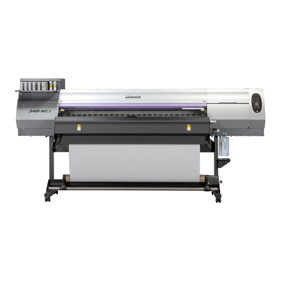
MIMAKI JV400-LX Series Operation Manual
Color inkjet printer
Hide thumbs
Also See for JV400-LX Series:
- Maintenance manual (268 pages) ,
- Installation manual (50 pages) ,
- Requests for daily care and maintenance (16 pages)

Subscribe to Our Youtube Channel
Related Manuals for MIMAKI JV400-LX Series


Summary of Contents for MIMAKI JV400-LX Series
- Page 1 MIMAKI ENGINEERING CO., LTD. URL: http: // www.mimaki. co. jp/ D202283-10 Original instructions...
-
Page 2: Table Of Contents
TABLE OF CONTENS CAUTION ................v DISCLAIMER OF WARRANTY ........v Requests ................. v FCC Statement (USA) ............. v Interference to televisions and radios ......v Foreword ................vi About usable ink ..............vi On This Operation manual ..........vi Safety Precautions ............. vii Symbols ................vii Safety interlock .............. - Page 3 Preparing for the Heaters ..........2-17 Changing the Temperature Settings for the Heaters ..2-17 Checking the Heater Temperature .........2-18 Changing the Temperature Settings for the Drying Fan Heater ..........2-18 Test Feeding ..............2-19 Test Printing ..............2-20 Test Printing ..............2-21 Head Cleaning ..............
- Page 4 Maintaining the Capping Station ........4-5 Cleaning the Wiper and Cap ..........4-5 Washing the Ink Discharge Passage (DISWAY WASH) .. 4-8 When the Machine Is Not Used for a Long Time (CUSTODY WASH) ............4-10 Cleaning the Ink Head and the Area around It ....4-12 When Nozzle Clogging Cannot Be Solved ......4-14 Washing of Head nozzle ..........
-
Page 6: Caution
Operation of this equipment in a residential area is likely to cause harmful interference in which case the user will be required to correct the interference at his own expense. In the case where MIMAKI-recommended cable is not used for connection of this device, limits provided by FCC rules can be exceeded. -
Page 7: Foreword
Foreword Congratulations on your purchase of MIMAKI color ink jet printer "JV400 Series" . “JV400 Series” is a color inkjet printer that can print with LX ink realizing high image quality. About usable ink Usable ink for this machine is LX100 ink (four-color / six-color / six-color+white model). -
Page 8: Safety Precautions
Safety Precautions Symbols Symbols are used in this Operation Manual for safe operation and for prevention of damage to the machine. The indicated sign is different depending on the content of caution. Symbols and their meanings are given below. Please follow these instructions as you read this manual. Examples of symbols Meaning Failure to observe the instructions given with this symbol can result in death or serious injuries... - Page 9 Check first that the machine no longer produces smoke, and then contact your distributor or a sales office of MIMAKI for repair. • Never repair your machine by yourself since it is very dangerous for you to do so.
- Page 10 • The machine does not operate with any ink other than the Handling of media JV400 genuine ink. • Use media recommended by MIMAKI to ensure reliable, • Do not use the JV400 genuine ink with other printers, as high-quality printing.
-
Page 11: Safety Interlock
Safety Precautions Cautions on Installation CAUTION A place exposed to direct A place where temperature or On an inclined surface sunlight humidity varies significantly • Use the machine under the following environmental conditions: • Operating environment: 20 to 35 °C (68 to 95 °F) 35 to 65 % (Rh) A place exposed to direct air... - Page 13 Chapter 1 Before Use This chapter describes the items required to understand before use, such as the name of each part of the machine or the installation procedures. Moving This Machine ........1-2 Connecting Cables ........1-10 Where to Install This Machine ..... 1-2 Connecting USB2.0 Interface Cable ..1-10 Working Environmental Temperature ..
-
Page 14: Moving This Machine
Moving This Machine Where to Install This Machine Secure a suitable installation space before assembling this machine. The place of installation must have enough space for not only this machine itself, but also for the printing operation. Model Width Depth Height Gross weight JV400-130LX... -
Page 15: Moving This Machine
Moving This Machine Moving This Machine Move this machine according to the following steps when this machine needs to be moved on the same step- free floor. • When the machine is moved to any place other than on the same step-free floor, contact your distributor or our service office. -
Page 16: Names Of Parts And Functions
Names of Parts and Functions Front Side of the Machine Left maintenance cover Front cover Open the cover in maintenance. Open the cover in setting of medias, taking of measures Even when the power switch is off, keep all covers against jamming of medias or in maintenance inside the closed. -
Page 17: Rear Side And Right Side Of The Machine
Names of Parts and Functions Rear Side and Right Side of the Machine Pre-heater Clamp lever (rear) Preheats the media before printing. (Located inside the platen) Interlocks with the clamp lever in the font of this machine. Cleaning solution cartridge Set a dedicated Washings cartridge (optional). -
Page 18: Operation Panel
Operation Panel Use the operation panel to make settings for printing or operate this machine. Display CONSTANT lamp Displays the status of the Lights in green when the heater temperature machine, set items and errors. reaches the set temperature. HEAT lamp Lights in orange during heating up of the heater. -
Page 19: Heater
Names of Parts and Functions Heater Pre-heater/Print heater/Post-heater are equipped on the platen. The Pre-heater is used for pre-heating of the media prior to printing to prevent rapid changes in temperature. The Print-heater improves the image quality in printing.The Post-heater and drying-heater dries ink after printing. -
Page 20: Carriage
Carriage The carriage is provided with the ink heads for printing, the cutter unit for cutting off the sheet of media, etc. A lever is also provided to adjust the height of Head in 3 stages according to the thickness of media. ( P.2-5) Cutter blade and slot for cutting The carriage is provided with a cutter unit for cutting off the media that has been printed on. -
Page 21: Capping Station
Names of Parts and Functions Capping station • Be sure to wear the attached goggles in cleaning within the capping station to protect your eyes against ink. Otherwise, you may get ink in your eyes. The capping station consists of the ink caps, the wiper for cleaning the heads, etc. -
Page 22: Connecting Cables
Connecting Cables Connecting USB2.0 Interface Cable Connect the PC and this machine with the USB2.0 USB cable interface cable. • Your RIP must be compatible with USB 2.0. • Contact a RIP maker near your location or our office when the USB2.0 interface is not attached to the PC. -
Page 23: Connecting The Power Cable
Connecting Cables Removing USB memory If a USB memory module is inserted in the personal computer to which a JV400 machine is connected, click "Stop" in the "Safely Remove Hardware" window by following the instructions given there first and then remove the module. -
Page 24: Inserting Ink Cartridges
Inserting ink cartridges Insert an ink cartridges. Shake the ink cartridge as shown on the right. Insert the ink cartridge. • Insert the ink cartridge lengthwise with the surface having IC chips pointing to the left side. • For the setting orders of the ink cartridges, refer to P.6-4. Changing an ink cartridge Perform as follows when [INK END] or [INK NEAR END] is displayed on the display. - Page 25 Inserting ink cartridges For Ink cartridge lamps The condition of the ink cartridges set in the machine is confirmable with lamps located over the ink cartridges. Ink cartridge lamps Condition of Lamp Description No error There is less ink in the ink cartridge (Near End), or ink has expired.
-
Page 26: Caution In Handling Of Ink Cartridges
• Do not shake ink cartridges violently. This may result in ink leakage from the ink cartridges. • Never refill the ink cartridges with ink. This may result in troubles. MIMAKI will not bear any responsibility for any damage caused by the use of the ink cartridges refilled with ink. -
Page 27: Media
Caution in handling of medias Pay attention to the followings for handling of medias. • Use media recommended by MIMAKI to ensure reliable, high-quality printing. Set the heater temperature to meet the characteristics of the media. • Set the temperature of the Pre-heater, Print heater and Post-heater according to the type and characteristics of the media used. -
Page 28: About Antistatic Sheet
About antistatic sheet The electrostatic sheet is used to prevent the media from clinging due to static. Use this when static or deflection of the media on the post heater occurs and affects the media feeding. Fix the electrostatic sheet ... - Page 29 Chapter 2 Basic Operations This chapter describes procedures and setting methods for ink and media preparation, and printing. Workflow ............2-2 Test Feeding ..........2-19 Turning the Power ON/OFF ......2-3 Test Printing ..........2-20 Turning the Power ON ........ 2-3 Test Printing ..........2-21 Turning the Power OFF .......
-
Page 30: Workflow
Workflow Turning the Power ON/OFF Referring to “Turning the Power ON/OFF” P.2-3). Setting a Media Referring to “Setting a Media” ( P.2-5). Preparing for the Heaters Referring to “Preparing for the Heaters” P.2-17). Test Printing Referring to “Test Printing” ( P.2-20). -
Page 31: Turning The Power On/Off
Turning the Power ON/OFF Turning the Power ON This machine is provided with the following two power switches: Main power switch:It is located on the side of this machine.Keep this switch ON all the time. Power switch : Normally, use this switch to turn the power ON/OFF. The power switch lights in green when the power is ON. -
Page 32: Turning The Power Off
Turning the Power ON/OFF Turning the Power OFF When having ended the operation of the machine, turn the power OFF by pressing the power switch located on the front side. Check the following items when turning the power OFF. • If the machine is receiving data from the PC or if there is any data that has not been output yet •... -
Page 33: Setting A Media
Setting a Media This machine can be used with a roll media and leaf media. For usable medias, refer to P.1-15 “Usable sizes of media”. Adjusting the Head Height Adjust the head height according to the thickness of the media you use. •... - Page 34 Fix the carriage. • Fastening the screw in front, you can fix the carriage. • Fasten the screw securely. Fix the carriage. Return the carriage to the station position.
-
Page 35: Note For Media Setting
Setting a Media Note for media setting When setting media, read the following notes carefully. • Take care not to drop the media on a foot or so when the media is set. It may cause an injury due to the media. •... -
Page 36: Setting A Roll Media
Setting a roll media Roll holder Move the roll holder located in the back of the device to the direction of the middle of the device. • Loosen the roll holder fixing screw and then move it. Roll holder fixing screw Check the clamp lever is lowered. - Page 37 Setting a Media Clamp lever Raise the clamp lever in the front of this machine. Insert the roll media in this machine. Pinch roller • The roll media can be smoothly inserted by slanting the media. (1) Pull the media out of the roll to the head of the platen. (2) Insert the media between the platen and the pinch roller.
- Page 38 Hold the media with the media press gently. • Set the media so that no media sticks out from the right end pinch roller to the right side. • When using a thick media, remove the media press from the media before printing. Media press •...
- Page 39 Setting a Media Front cover Prepare for the take-up device. Drying heater cover (1) Set an empty core of the roll media on the take-up device. (2) Close the front cover. (3) Close the drying heater cover. Paper core Take-up device Press the key to select "ROLL"...
- Page 40 Entering the media remaining amount When [MEDIA RESIDUAL] of the maintenance function is "ON" ( P.3-9), the screen for entering media remaining amount is displayed after detecting the media width. Display the screen for entering media remaining I n p u t o f Me d i a L e n g t h MED I A L ENGH T = x x x .
-
Page 41: Take-Up Device
Setting a Media Take-up device With the switch of the take-up device, select the take-up direction of the media or others. Lever in top position (REVERSE) : The take-up device winds the media with the printed side facing in. Lever in middle position (OFF) : The take-up device does not wind the media. -
Page 42: Setting Leaf Media
Setting leaf media Unlike roll media, leaf media does not need to be retained with the roll holders. Open the front cover. Front cover Raise the clamp lever. Clamp lever Insert the leaf media between the platen and the pinch rollers. •... - Page 43 Setting a Media Press the key. Press the key to select "LEAF" . MED I A S E L EC T RO L L < > L EA F The media detection is started. * * MED I A DE T EC T * * (1) The media width is detected.
-
Page 44: Changing The Printing Origin
Setting a Media Changing the printing origin The position of the printing origin can be changed. Moving the LED pointer to the changing position and deciding the position. When the heavy-duty feeding / take-up device is not used In Local, Press OR I G I N SE T UP 0 . -
Page 45: Preparing For The Heaters
Preparing for the Heaters Changing the Temperature Settings for the Heaters Set the heater temperature. Depending on the media and the profile to use, set the heater temperature. • It may take several minutes to tens of minutes for the set temperature to be reached, depending on the ambient temperature. -
Page 46: Checking The Heater Temperature
Preparing for the Heaters Checking the Heater Temperature Press the key. PR T POS T 3 5 C 4 0 C 5 0 C • The current heater temperature is displayed. Press the key at the end of confirmation. •... -
Page 47: Test Feeding
Test Feeding Since heater is used at high temperature, cockles may occur in some of your media. ( P.5-11) Perform this function before printing, and check whether the media can be fed normally. Press the key in LOCAL twice. T E S T F E ED [ EN T ] Press the key. -
Page 48: Test Printing
Test Printing Print a test pattern to check that there are no discharging defects such as nozzle clogging (slight touching of ink or nozzle missing). Relationship between head row and test pattern The relations between head row and test pattern print position are as follow. Head 1 Head 2 Pattern of head 1... - Page 49 Test Printing Test Printing Print a test pattern to check that there are no discharging defects such as nozzle clogging (slight touching of ink or nozzle missing). In addition, you can select the orientation of the test pattern to print from two types in order to perform test printing repeatedly.
-
Page 50: Head Cleaning
Head Cleaning About head cleaning Check the printed test pattern result and perform cleaning depending on the status. Select one from the three types below: SOFT : When lines are bent, when any line is missing NORMAL : When any line is missing, when colors are mixed HARD : When poor image quality cannot be improved even by NORMAL or SOFT cleaning Perform head cleaning depending on the test printing result... -
Page 51: Set The Media Feeding Amount
Set the media feeding amount Correct the feeding rate of media. If the correction value is not appropriate, stripes may appear on the printed image, thus resulting in a poor printing. • When you have changed the media type, check the pattern and perform adjustment depending on the status. - Page 52 Set the media feeding amount Press the key. F E ED COMP . PR I N T [ EN T ] • Print a correction pattern again and check it. • When media correction is needed, perform the operation in Step 5 to make correction.
-
Page 53: Correct The Ink Drop Position For Bidirectional Printing
Correct the ink drop position for bidirectional printing When the condition for printing (media thickness/head height/etc.) has been changed, perform the following operation to correct the ink drop position for bidirectional (Bi) printing and obtain the proper printing result. Example of a Drop Position correct Printed Pattern Output direction The dots at the fourth position counted from the zero... - Page 54 Correct the ink drop position for bidirectional printing Press the key. Press the key several times to end the setting. Performing to correct the dot position without You can select “DROP.POScorrect” by using the key in the Local without pressing the key.
-
Page 55: Printing Data
Printing Data Starting a Printing Operation • When using a roll media, rewind the media by hand before printing so that it is not loose.When the roll media has not been rewound tightly, it may cause the image quality to deteriorate. Setting a Media ( P.2-5) Checking the Heater Temperature... -
Page 56: Stopping A Printing Operation Halfway
Stopping a printing operation halfway Perform the following operation when stopping a printing operation halfway. Press the key during printing. < L OCA L > w i d t h : 1 2 7 2 mm • The printing operation stops. •... -
Page 57: Cutting A Media
Printing Data Cutting a media For a roll media, two ways are available to cut the media after printing is completed, as follows. • When a media is cut, be careful that the printed side does not touch the floor or the printed side of other already cut media. - Page 58 2-30...
- Page 59 Chapter 3 Extended Functions This chapter describes the operation procedures for using the machine more conveniently and each setting procedure. List of Functions ..........3-2 Confirming Machine Information ....3-17 Setting Logical Seek ........3-3 Displaying the Information ......3-17 Displaying the Information of this machine .3-18 Setting Drying Time ........
-
Page 60: List Of Functions
List of Functions This section describes the overview of each function to be set and set values that can be registered in user types. • About default “HOST” function You can operate this by the setting value specified in RIP software. When you set to other than “HOST”, it operates by that setting value, not by the instruction from RIP software. -
Page 61: Setting Logical Seek
Setting Logical Seek The motion of Head varies depending on the set of Logical-seek. • You cannot specify the logical seek at the RasterLinkPro side. When you set this machine to “Host”, printing will be performed in “LOGICAL SEEK=OFF” status. •... -
Page 62: Setting Drying Time
Setting Drying Time In the drying time setting, the following items for ink drying time are set. • SCAN : Ink drying time for each scanning is set. (During bidirectional printing, the machine stops for a certain period of time specified for each of the outward and return scanning.) •... -
Page 63: Setting Margins
Setting Margins Set a non-printing area along the right and left edges of the media. The offset value against the standard margin 15mm is set hereupon. • When you give priority to the setting at the RIP software side, make the setting value “Host”. •... -
Page 64: Setting Nozzle Face Cleaning Time
Setting nozzle face cleaning time When the set time has passed, nozzle face of the head is cleaned automatically to remove ink droplets on the nozzle face. In case that deflection, nozzle missing, or symptom which ink droplets fall down occurred, make the interval between each operation shorter. -
Page 65: Other Settings
Other Settings Change the settings according to the types of use. Press the key in LOCAL. F UNC T I ON S E T UP [ EN T ] Press the key. S E T UP F E ED COMP . [ EN T ] Press to select an item for setting. -
Page 66: Machine Settings
Machine Settings Common settings are functions for using this machine easily. The following items can be set in Machine settings. Item Set value Default Meaning When no operation has been performed for the NONE/ AUTO Power-off 30min set time, the power supply is automatically 10 ~ 600min turned “OFF”. -
Page 67: Setting A Auto Power-Off
Machine Settings Setting a AUTO Power-off When no operation has been performed for the set time, the power supply is automatically turned “OFF”. Press the key in LOCAL. F UNC T I ON S E T UP [ EN T ] Press to select [MACHINE SETUP]. -
Page 68: Setting The Display Of Media Residual
Setting the Display of Media Residual Whether the screen displays the remaining amount of a media is set. the remaining amount of a media is displayed in Remote. When the media remaining amount (However, when a leaf media is used, the length of the media to be display is turned to "ON"... - Page 69 Machine Settings Printing the Remaining Amount of a Media The present remaining amount of a media can be printed. • Set "Remaining amount of a media to display" to "ON". • When you replace the media you use now with another, it is recommended that you print the remaining amount of the media on it.With the remaining amount of a media having been printed beforehand, when you use the replaced media again, you can enter an accurate value in the screen for entering the remaining amount of a media (...
-
Page 70: Setting Time
Setting Time You can set time of your country (time difference). Press the key in LOCAL. F UNC T I ON S E TUP [ EN T ] Press to select [MACHINE SETUP]. F UNC T I ON MACH I NE SE T UP [ EN T ] Press the key. -
Page 71: Setting Units
Machine Settings Setting Units Units used by this machine are set. Press the key in LOCAL. F UNC T I ON S E T UP [ EN T ] Press to select [MACHINE SETUP]. F UNC T I ON MACH I NE SE T UP [ EN T ] Press the key. -
Page 72: Setting A Key Buzzer
Setting a KEY BUZZER You can turn off the buzzer sound when pressing the key. Press the key in LOCAL. F UNC T I ON S E TUP < EN T > Press to select [MACHINE SETUP]. F UNC T I ON MACH I NE SE T UP [ EN T ] Press the... -
Page 73: Setting A Language
Machine Settings Setting a LANGUAGE You can change the displayed language. Press the key in LOCAL. F UNC T I ON S E T UP [ EN T ] Press to select [MACHINE SETUP]. F UNC T I ON MACH I NE SE T UP [ EN T ] Press the key. -
Page 74: Initializing The Settings
Initializing the Settings You can return the setting of “SETUP”, “MAINTENANCE” and “MACHINE SETUP” to the status before shipment. Press the key in LOCAL. F UNC T I ON S E TUP [ EN T ] Press to select [MACHINE SETUP]. F UNC T I ON MACH I NE SE T UP [ EN T ]... -
Page 75: Confirming Machine Information
Confirming Machine Information The information of this machine can be confirmed. The following items can be confirmed as machine information. Item Description WIPING WASTE INK TANK FILTER USAGE PRINT LENGTH PRINT AREA USE TIME VERSION This displays the firmware version of the machine. Displaying the Information Press the key in LOCAL. -
Page 76: Displaying The Information Of This Machine
Confirming Machine Information About Displayed Information This section describes how to read displayed information. WIPING WASTE INK TANK Displays wiping Displays waste ink tank WI P I NG W ASTE I NK TANK information. information. FILTER PRINT LENGTH Displays filter Displays printed length F I L TER PR I NT LENGTH... -
Page 77: Maintenance
Chapter 4 Maintenance This chapter describes the items required to use this machine more comfortably, which are the methods for the daily care, the maintenance of the ink unit etc. Maintenance ..........4-2 Cleaning the Ink Head and the Area Precautions for Maintenance ...... -
Page 78: Maintenance
Maintenance Maintain the machine regularly or as necessary so that its accuracy will be maintained and it can continue to be used for a long time. Precautions for Maintenance Pay attention to the following items when maintaining this machine. • When using cleaning solution for maintenance, be sure to wear the supplied protective glasses. •... -
Page 79: Cleaning The Exterior Surfaces
Maintenance Cleaning the Exterior Surfaces When the exterior surfaces of the machine are stained, dampen a soft cloth with water or a neutral detergent diluted with water, squeeze it, and wipe the surfaces with the cloth. Cleaning the Platen The platen easily gets dirty with lint, paper dust, etc. generated when a media is cut. -
Page 80: Cleaning The Media Sensor
Maintenance Cleaning the Media Sensor The media sensors are located on the platen in the backside and the bottom surface of the head. When the sensor is covered with dust, etc., it may cause false detection of media. Using a cotton swab, remove the dust, etc. accumulated on the surface of the sensor. When cleaning the sensor on the lower surface of the head is cleaned, move the carriage to the left end by the operations of step 1 of P.4-12 “Cleaning the Ink Head and the Area around It”, and then clean it. -
Page 81: Maintaining The Capping Station
Maintaining the Capping Station Maintain the ink cap, wiper, etc. located in the capping station. (SATION MAINT.) The ink cap and wiper function as follows. • Wiper : It wipes off ink sticking to the head nozzles. • Ink cap : It prevents the head nozzles from clogging due to dryness. As the machine is used repeatedly, the wiper and ink cap gradually become dirty with ink, dust, etc. - Page 82 Open the front cover then remove the wiper. Projection • Pull out the wiper by holding the protrusions at its both ends. Clean the wiper and bracket. Wiper • Wipe off the ink sticking to the wiper and bracket with a clean stick dipped in cleaning solution for maintenance.
- Page 83 Maintaining the Capping Station Close the front cover then press the key. C l o s e a c o v e r • After its initial operation, the machine returns to LOCAL. * B e i n g I n i t i a l i z e d * P L E A SE WA I T Performing the station maintenance without MAINT.
-
Page 84: Washing The Ink Discharge Passage (Disway Wash)
Washing the Ink Discharge Passage (DISWAY WASH) Wash the ink discharge passage regularly to prevent the head nozzles from clogging due to ink coagulation inside the passage. Press the key in LOCAL. S T A T I ON MAINT. CARR I AGE OU T [ EN T ] Press to select [DISWAY WASH]. - Page 85 Maintaining the Capping Station Close the front cover and press the key. * B e i n g I n i t i a l i z e d * P L E A SE WA I T < L OCA L > •...
-
Page 86: When The Machine Is Not Used For A Long Time (Custody Wash)
When the Machine Is Not Used for a Long Time (CUSTODY WASH) When the machine is not going to be used for a week or more, use the cleaning function for custody to clean the head nozzles and ink discharge passage.After this, keep the machine in custody. Is [NEAR END] or [INK END] displayed? •... - Page 87 Maintaining the Capping Station Fill up the cap with cleaning solution for maintenance. • If the cleaning solution cartridge is usable, cleaning solution is automatically filled. • If the cleaning solution cartridge is not usable, suck maintenance cleaning solution into a dropper and fill up the cap with it.
-
Page 88: Cleaning The Ink Head And The Area Around It
Cleaning the Ink Head and the Area around It Because the ink head employs a very precise mechanism, due care needs to be taken when it is cleaned. Using a clean stick, etc., rub off gelatinous ink or dust that may stick to the lower part of the slider and the area around the ink head.In doing so, never rub the nozzles of the head. - Page 89 Cleaning the Ink Head and the Area around It Wipe ink sticking to the side of the head off with a clean stick. • Never rub the nozzles. Clean the side surface of the head (shown in deep gray) with a clean stick. The nozzle part (Never touch it.) Clean with a clean stick or a waste cloth.
-
Page 90: When Nozzle Clogging Cannot Be Solved
When Nozzle Clogging Cannot Be Solved When nozzle clogging cannot be solved even after the ink head cleaning ( P.2-22) has been done, perform the following two functions: NOZZLE WASH • Wash the head nozzle. ( P.4-14) • Alternative nozzles for printing, when nozzles missing can not be improved. NOZZLE RECOVERY P.4-17) Washing of Head nozzle... - Page 91 When Nozzle Clogging Cannot Be Solved Clean the cap rubber and cap rubber cover. • Wipe off the ink sticking to the cap rubber and cap rubber cover with a clean stick dipped in cleaning solution for maintenance. Wipe off so that cleaning solution for maintenance will not remain.
- Page 92 Press the key. C l o s e a c o v e r • The cleaning solution filled in the cap is absorbed. • The screen on the right is displayed only for the duration set in the step 9. •...
-
Page 93: Alternative Nozzles For Printing, When Nozzles Missing Can Not Be Improved
When Nozzle Clogging Cannot Be Solved Alternative nozzles for printing, when nozzles missing can not be improved NOZZLE RECOVERY: When nozzles missing can not be improved at specific points, other good nozzles can be used as alternatives for printing. Select [NOZZLE RECOVERY] of the maintenance menu. - Page 94 Register the Nozzle number that needs NOZZLE H 1 - A RECOVERY and then press key. N o . 1 : 1 8 4 • Select the registration number from 1 to 10 by pressing key and press the Recovery nozzle No.: •...
- Page 95 When Nozzle Clogging Cannot Be Solved Clear the set value Select [HD.MAINTENANCE] of the maintenance menu. (1) Press the key in LOCAL. (2) Press to select [MAINTENANCE] and press the key. (3) Press to select [HD. MAINTENANCE]. (4) Press the key.
-
Page 96: Automatic Maintenance Function
Automatic Maintenance Function To use this machine comfortably, you can set various maintenances to be performed automatically. Here, set performing intervals of various automatic maintenances. You can prevent troubles such as ink clogging by performing automatic maintenance periodically (automatic maintenance function). For the auto maintenance functions, the following items can be set: •... -
Page 97: Setting The Cleaning Intervals
Automatic Maintenance Function Setting the Cleaning Intervals The cleaning type and the interval between each cleaning operation are set. Select [AUTO MAINT.] of the maintenance menu. (1) Press the key in LOCAL. (2) Press to select [MAINTENANCE] and press the key. -
Page 98: Replacing Consumables
Replacing consumables Replacing the wiper The wiper is consumable.When the display indicates that it is necessary to < L OCA L > replace the wiper, immediately replace the wiper with a new one. ! R e p l a c e Wi p e r [ M N T ] Also, wipe ink sticking to the lower surface of the slider off. -
Page 99: If A Waste Ink Tank Confirmation Message Appears
Replacing consumables If a Waste Ink Tank Confirmation Message Appears Ink used in head cleaning, etc. is stored in the waste ink tank on the lower right side of the machine.This machine counts the accumulated amount of discharged ink. When that reaches a specified amount, the machine displays a confirmation message.(When this message is displayed, consider the replacement of the waste ink tank.) •... - Page 100 Replace the waste ink tank with another Press the waste ink tank guard downward to open Waste ink tank to the front. guard Press downward and pull it Pull it frontward to remove by holding the waste Waste ink tank ink tank handle.
- Page 101 Replacing consumables Close the waste ink tank guard. Press the key. COUN T C L EAR E X ECU T E [ MN T ] • The ink discharging amount that is controlled by the machine is reset and the message is cancelled. 4-25...
-
Page 102: Replacing The Cutter Blade
Replacing the Cutter Blade The cutter blade is consumable.When the cutter blade gets dull, replace it with a new one (SPA-0107). • The blade is sharp.Be careful not to hurt yourself or anyone else. • Store the cutter blade in a place that is out of the reach of children.In addition, dispose of used cutter blades according to regional laws and regulations. - Page 103 Replacing consumables Close the front cover. Press the key. • The screen returns to LOCAL. 4-27...
- Page 104 4-28...
- Page 105 Chapter 5 Troubleshooting This chapter describes the corrective measures to be taken for a phenomenon suspected to be trou- ble and the procedures to clear the error number displayed on the LCD. Troubleshooting ................5-2 Power does not turn on ..............5-2 The machine does not start printing ..........5-2 Media get jammed / media is soiled ..........5-3 [HEAT] or [CONSTANT] LED does not light up .......5-3...
-
Page 106: Power Does Not Turn On
Troubleshooting Take appropriate actions as described below before taking the trouble as a failure. If still the problem is not solved after troubleshooting, contact your dealer or an office of MIMAKI. Power does not turn on In most cases, this is due to improper connection of the power cable for the machine or computer. Check that the power cable is connected properly. -
Page 107: Media Get Jammed / Media Is Soiled
Troubleshooting Media get jammed / media is soiled Media jamming or stained media is considered to be due to the use of an unsuitable media or improper setting of media. Is a recommended media used ? Use recommended media. Is the media not curled or bent ends ? Avoid using any media with curls or bent ends. -
Page 108: Image Quality Is Poor
This section describes the corrective actions to be taken in case the image quality is not satisfactory. Take remedy for particular problems with image quality. If the remedy does not work, contact your dealer or an office of MIMAKI. Phenomenon Measures (1) Execute the head cleaning. -
Page 109: Ink Cartridge Warning Appears
• Once cartridge trouble is displayed, do not leave the ink cartridge without replacing it for a long time; otherwise, the machine will lose the nozzle clogging prevention function. If nozzles are clogged, the machine must be repaired by MIMAKI's service engineer. Displaying the description of ink cartridge trouble The contents of cartridge error are confirmable by the following operations. -
Page 110: When Error 611 To 614 Occur
When Error 611 to 614 occur Execute following procedures when an error about subtank occurs, or when the nozzle is not unclogged after cleaning. Select [SUB TANK] of the maintenance menu. (1) Press the key in LOCAL. (2) Press to select [MAINTENANCE] and press the key. -
Page 111: Regular Maintenance Of White Ink
Troubleshooting Regular maintenance of white ink White ink precipitates easier than other inks. • If not printing more than two weeks, white ink may precipitate in the ink cartridge or inside of this machine. • When an ink precipitates, the nozzle may be clogged and it can not draw normally. •... - Page 112 When the cartridge is pulled out, the discharging * * D I SCHARGE * * operation starts. P L E A SE WA I T • White ink discharge starts. Slowly shake the white ink cartridge more than twenty times right and left. •...
- Page 113 Troubleshooting When the next screen is displayed, set the white ink S E T CAR T R I DGE : _ _ _ _ _ _ 7 8 cartridge to the ink station again. When you insert the cartridge, ink filling starts. * * F I L L I NG * * P L E A SE WA I T When the next screen is displayed, fill ink into the...
-
Page 114: If Negative Pressure Abnormality Occurs
If negative pressure abnormality occurs By the environment or aging, the pressure controlled in this machine may exceed the control range. • When error display of (1) appears, immediately adjust the pressure as the following procedures to reset to the normal value. •... -
Page 115: When Media Heaves Up At Feeding
Troubleshooting Rotate the adjustment screw of the throttle valve to PRES SURE - 2 . 4 0 k P a adjust the pressure so that it becomes the proper value. • Proper value of negative pressure: -2.40kPa Proper value of positive pressure: 15.00kPa •... -
Page 116: Warning / Error Messages
Warning / Error Messages If some trouble occurs, the buzzer sounds and the display shows a corresponding error message. Take an appropriate remedy for the displayed error. Warning messages Errors when performing operations Message Cause Solution Check the front cover and maintenance covers. - Page 117 Warning / Error Messages Ink Error Ink error is displayed also in the local guidance. ( P.3-17) Message Cause Solution Remove the cartridge generating the I N K I C C A N ‘ T R E A D warning once and install it again. : - - - - Y Y K K The IC chip of the ink cartridge can-...
-
Page 118: Error Messages
Error messages When an error message is displayed, eliminate the error according to the chart below. If the same error message appears again, contact your dealer or an office of MIMAKI to call for service. Message Cause Solution Head connection can not be con- E R ROR 1 0 8 firmed. - Page 119 Warning / Error Messages Message Cause Solution An error occurred in the main PCB E R ROR 1 5 8 3.3VB power supply. M a i n P C B V 3 R 3 B COM driver becomes the high tem- E R ROR 1 5 f perature.
- Page 120 Message Cause Solution E R ROR 5 0 5 The media jam occurs. Remove the media and reset it. ME D I A J AM L Check the media set position. ( P.2- The media width has not been E R ROR 5 0 6 detected correctly.
- Page 121 Warning / Error Messages Message Cause Solution There is a slot in which the cartridge E R ROR 6 2 7 has not been inserted more than a Set a cartridge. I N S E R T C A R T R I DG E certain time.
- Page 122 5-18...
- Page 123 Chapter 6 Appendix This chapter contains the lists of the specifications and functions of this machine. Specifications ..................6-2 Machine specifications ..............6-2 Ink specifications ................6-3 Setting orders depending on ink type ..........6-4 Setting orders of ink cartridges ............6-4 Sheet for inquiry ................6-5 Warning labels .................6-6 Function Flowchart ................6-8...
-
Page 124: Specifications
Specifications Machine specifications Item JV400-130LX JV400-160LX Method Drop-on-demand piezoelectric print heads Print head Specification 2 head 900x900 : Bi/Uni 6/12/24pass 900x1200 : Bi/Uni 8/16/32pass 1200x1200 : Bi/Uni 8/16/32pass 4-color 600x900 : Bi/Uni 6/12/24pass 600x1200 : Bi/Uni 8/16/32pass Drawing 600x600 : Bi/Uni 4/8/16/32pass mode (scan 900x900 : Bi/Uni 6/12/24/48pass x feed) -
Page 125: Ink Specifications
Specifications Item JV400-130LX JV400-160LX during standby Less than 58 dB (FAST-A, Front & Rear & Left & Right 1 m) Noise during continuous printing Less than 65 dB during discontinuous printing Less than 75 dB VCCI-Class A, FCC-Class A, UL 60950, CE Marking (EMC,Low Voltage Direc- Safety Standard tive,Machinery Directive), CB Report, RoHS Power... -
Page 126: Setting Orders Depending On Ink Type
Setting orders depending on ink type The setting value and the setting orders of the ink cartridges differ depending on the ink type you use. Setting orders of ink cartridges The orders of ink cartridges set in the ink station differ depending on the ink set you use. •... -
Page 127: Sheet For Inquiry
Sheet for inquiry Use this sheet for troubles and abnormal functions of the machine. Fill in the following necessary items, and then fax the sheet to our sales office. Company name Person in charge Telephone number machine model Operating OS Machine information Error message Contents of inquiry... -
Page 128: Warning Labels
Warning labels Warning labels are stuck on the machine. Be sure to fully understand the warning given on the labels. If a warning label is illegible due to stains or has come off, purchase a new one from a distributor or our sales office. - Page 129 Warning labels No. Reorder M907833 M903239 M903330 M903405 M906144 M908553 M907935 M908546 (JV400-130LX) M908545 (JV400-160LX) M908546 M908545...
-
Page 130: Function Flowchart
Function Flowchart < L OC A L > WH I D T H : * * * * mm OR I G I N S E T U P OR I G I N S E T U P 0 . 0 - - - - * * OR I G I N * * ME D I A CU T... - Page 131 Function Flowchart T E S T F E E D * * T E S T F E E D * * [ E N T ] P L E A S E WA I T * * C L E A N I NG * * P L E A S E WA I T CU T POS I T I ON 0 .
- Page 132 From P.6-8 F E E D COMP . F E E D COMP . ADJUST [ E N T ] P R I N T [ E N T ] ADJUST DROP . POS c o r r e c t DROP .
- Page 133 Function Flowchart * * P R I N T I NG * * F E E D COMP . P L E A S E WA I T -255 to 255 * * P R I N T I NG * * P A T T E RN 1 P A T T E RN 2 P L E A S E WA I T...
- Page 134 < L OC A L > F UNC T I ON SETUP WH I D T H : * * * * mm S E T U P [ E N T ] F UNC T I ON MAINTENANCE MA I N T E N A NC E [ E N T ] F UNC T I ON MACHINE SET...
- Page 135 Function Flowchart To P.6-14 To P.6-18 To P.6-22 W I P I NG WA S T E I N K T A N K F I L T E R P R I N T L E NG T H P R I N T A R E A U S E T I ME >...
- Page 136 SETUP S E T U P F E E D COMP . * * P R I N T I NG * * F E E D COMP . [ E N T ] P R I N T [ E N T ] P L E A S E WA I T S E T U P DROP .
- Page 137 Function Flowchart F E E D COMP . Print end -255 to 255 P A T T E RN 1 P A T T E RN 2 Print end 0 . 0 0 . 0 -40.0 to 40.0 -40.0 to 40.0 POS T O F F OFF / 20 to 50C...
- Page 138 From P.6-14 S E T U P F E E D S P E E D F E E D S P E E D [ E N T ] HOS T HOST / 10 to 100% S E T U P I N T E R V A L W I P I NG I N T E R V A L W I P I NG [ E N T ] : A U T O...
- Page 139 Function Flowchart 6-17...
- Page 140 MAINTENANCE MA I N T E N A NC E S T A T I ON MOV EME N T P L A C E S T A T I ON [ E N T ] C A RR I AGE OU T [ E N T ] S T A T I ON MA I N T .
- Page 141 Function Flowchart C A RR I AGE OU T C l o s e a c o v e r To Local after initializing COMP L E T E D [ E N T ] F i l l t h e l i q u i d .
- Page 142 From P.6-18 MA I N T E N A NC E A U T O MA I N T . R E F R E S H A U T O MA I N T . [ E N T ] R E F R E S H [ E N T ] : L E V E L 1...
- Page 143 Function Flowchart T Y P E : NORMA L NORMAL / SOFT / HARD * * A D J U S T I NG * * P R E S S UR E P L E A S E WA I T 0 .
- Page 144 MACHINE SET MA CH I N E S E T U P A U T O P o w e r - o f f A U T O P o w e r - o f f [ E N T ] 3 0 m i n none/ 10 to 600min MA CH I N E S E T U P...
- Page 145 Function Flowchart 6-23...
- Page 146 6-24...
- Page 147 JV400-130LX/160LX Operation Manual December, 2011 MIMAKI ENGINEERING CO.,LTD. 2182-3 Shigeno-otsu, Tomi-shi, Nagano 389-0512 JAPAN D202283-10-22122011...
- Page 148 FW : 1.0 © MIMAKI ENGINEERING CO., LTD.2011...
Need help?
Do you have a question about the JV400-LX Series and is the answer not in the manual?
Questions and answers