
Related Manuals for MIMAKI JV400-130SUV


Summary of Contents for MIMAKI JV400-130SUV
- Page 1 MIMAKI ENGINEERING CO., LTD. URL: http://eng.mimaki.co.jp/ D202394-17 Original instructions...
-
Page 2: Table Of Contents
TABLE OF CONTENS CAUTION ................v DISCLAIMER OF WARRANTY ........v Requests ................. v FCC Statement (USA) ............. v Interference to televisions and radios ......v Foreword ................vi About usable ink ..............vi About usable media ............vi On This Operation manual ..........vi Safety Precautions ............. - Page 3 Changing the printing origin ..........2-13 Preparing for the Heaters ..........2-14 Changing the Temperature Settings for the Heaters ..2-14 Checking the Heater Temperature .........2-15 Test Feeding ..............2-16 Test Printing ..............2-17 Test Printing ..............2-18 Head Cleaning ..............2-19 About head cleaning ............2-19 Perform head cleaning depending on the test printing result ................2-19 Set the media feeding .............
- Page 4 Chapter 4 Maintenance Maintenance ..............4-2 Precautions for Maintenance ..........4-2 About Cleaning Solution ........... 4-2 Cleaning the Exterior Surfaces ......... 4-3 Cleaning the Platen ............4-3 Cleaning of after heater cover and pre heater cover ..4-4 Cleaning the Media Sensor ..........4-4 Cleaning the Media Holder ..........
- Page 5 Warning / Error Messages ..........5-12 Warning messages ............5-12 Error messages ..............5-15 Chapter 6 Appendix Specifications ..............6-2 Machine specifications ............6-2 Ink specifications ..............6-3 Setting orders depending on ink type ....... 6-4 Setting orders of ink cartridges .........6-4 Sheet for inquiry ..............6-5 Warning labels ..............
-
Page 6: Caution
Operation of this equipment in a residential area is likely to cause harmful interference in which case the user will be required to correct the interference at his own expense. In the case where MIMAKI-recommended cable is not used for connection of this device, limits provided by FCC rules can be exceeded. -
Page 7: Foreword
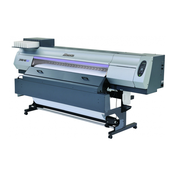
Foreword Congratulations on your purchase of MIMAKI color ink jet printer "JV400 SUV Series" . “JV400 SUV Series” is a color inkjet printer that can print with solvent UV ink realizing high image quality. About usable ink Usable ink for this machine is SU100 ink (four-color). -
Page 8: Safety Precautions
Check first that the machine no longer produces smoke, and then contact your distributor or a sales office of MIMAKI for repair. • Never repair your machine by yourself since it is very dangerous for you to do so. - Page 9 Then, distributor or a sales office of MIMAKI. consult a doctor as soon as possible. UV light • There is some leaking of ultraviolet radiation around the UV irradiation device.UV light applied to your skin might cause inflammation and/or skin cancer.Though weak UV light might cause no inflammation, repeated...
-
Page 10: Cautions And Notes
• The machine does not operate with any ink other than the Handling of media JV400 genuine ink. • Use media recommended by MIMAKI to ensure reliable, • Do not use the JV400-SUV genuine ink with other high-quality printing. printers, as doing so may cause damage to such •... - Page 11 • The UV lamp performance and service life are significantly affected by the UV irradiation and UV power supply units used.Never use those UV devices other than those recommended by Mimaki.We would take no responsibility for any troubles caused through the use of a UV devices not recommended by Mimaki.
-
Page 12: Safety Interlock
Safety Precautions Cautions on Installation CAUTION A place exposed to direct A place where temperature or On an inclined surface sunlight humidity varies significantly • Use the machine under the following environmental conditions: • Operating environment: 20 to 30 °C (68 to 95 °F) 35 to 65 % (Rh) A place exposed to direct air... - Page 13 Chapter 1 Before Use This chapter describes the items required to understand before use, such as the name of each part of the machine or the installation procedures. Moving This Machine ........1-2 Connecting Cables ........1-10 Where to Install This Machine ..... 1-2 Connecting USB2.0 Interface Cable ..1-10 Working Environmental Temperature ..
-
Page 14: Moving This Machine
500 mm or more or more 1000 mm or more JV400-130SUV: 3634 mm or more JV400-160SUV: 3879 mm or more Working Environmental Temperature Use this machine in an environment of 20 to 30°C to ensure reliable printing. The heater temperature may not reach the set value, depending on the ambient temperature. -
Page 15: Moving This Machine
Moving This Machine Moving This Machine Move this machine according to the following steps when this machine needs to be moved on the same step- free floor. • When the machine is moved to any place other than on the same step-free floor, contact your distributor or our service office. -
Page 16: Names Of Parts And Functions
Names of Parts and Functions Front Side of the Machine Left maintenance cover Front cover Open the cover in maintenance. Open the cover in setting of medias, taking of measures Even when the power switch is off, keep all covers against jamming of medias or in maintenance inside the closed. -
Page 17: Rear Side And Right Side Of The Machine
Names of Parts and Functions Rear Side and Right Side of the Machine Pre-heater Clamp lever (rear) Preheats the media before printing. Interlocks with the clamp lever in the (Located inside the platen) font of this machine. Cleaning solution cartridge Set a dedicated Washings cartridge (optional: FL007-Z-22). -
Page 18: Operation Panel
Operation Panel Use the operation panel to make settings for printing or operate this machine. Display CONSTANT lamp Lights in green when the heater temperature Displays the status of the reaches the set temperature. machine, set items and errors. HEAT lamp Lights in orange during heating up of the heater. -
Page 19: Heater
Names of Parts and Functions Heater Pre-heater/Print heater/Post-heater are equipped on the platen. The Pre-heater is used for pre-heating of the media prior to printing to prevent rapid changes in temperature. The Print-heater improves the image quality in printing.The Post-heater dries ink after printing. •... -
Page 20: Carriage
Carriage The carriage is provided with the heads for printing, the cutter unit for cutting off the sheet of media, etc. A lever is also provided to adjust the height of Head in 3 stages according to the thickness of media. ( P.2-5) Carriage Cutter blade and slot for cutting... -
Page 21: Capping Station
Names of Parts and Functions Capping station • Be sure to wear the attached goggles in cleaning within the capping station to protect your eyes against ink. Otherwise, you may get ink in your eyes. The capping station consists of the ink caps, the wiper for cleaning the heads, etc. -
Page 22: Connecting Cables
Connecting Cables Connecting USB2.0 Interface Cable Connect the PC and this machine with the USB2.0 USB cable interface cable. • Your RIP must be compatible with USB 2.0. • Contact a RIP maker near your location or our office when the USB2.0 interface is not attached to the PC. -
Page 23: Connecting The Power Cable
Connecting Cables Removing USB memory If a USB memory module is inserted in the personal computer to which a JV400 machine is connected, click "Stop" in the "Safely Remove Hardware" window by following the instructions given there first and then remove the module. -
Page 24: Inserting Ink Cartridges
Inserting ink cartridges Insert an ink cartridges. Slowly shake the white ink cartridge more than twenty times right and left. • To prevent ink from leaking when you shake the cartridge, wear gloves and firmly cover the A part of the upper surface of the cartridge and the B part of the bottom surface of the cartridge with paper towels. - Page 25 Inserting ink cartridges For Ink cartridge lamps The condition of the ink cartridges set in the machine is confirmable with lamps located over the ink cartridges. Ink cartridge lamps Condition of Lamp Description No error There is less ink in the ink cartridge (Near End), or ink has expired.
-
Page 26: Caution In Handling Of Ink Cartridges
• Do not shake ink cartridges violently. This may result in ink leakage from the ink cartridges. • Never refill the ink cartridges with ink. This may result in troubles. MIMAKI will not bear any responsibility for any damage caused by the use of the ink cartridges refilled with ink. -
Page 27: How To Assemble Ink Cartridge
Inserting ink cartridges How to assemble ink cartridge Before setting the ink cartridge, it is required to set the ink pack on the eco cartridge. By following the next procedures, assemble the ink cartridge. Open the cover of the eco cartridge. (1) Press the center part of the cover with your finger. - Page 28 (2) Peel the seal of double coated tape. Firmly fix the ink pack on the eco case with double coated tape so that it may not move. • Fix the ink pack after pulling it so that the ink pack may not go slack.
-
Page 29: Media
• Do not leave the media with the heater ON for a long time. Waviness may occur on the media and it may cause media clogging. • Use media recommended by MIMAKI to ensure reliable, high-quality printing. Set the heater temperature to meet the characteristics of the media. -
Page 30: About Antistatic Sheet
About antistatic sheet 130SUV: three antistatic sheets, 160SUV: four antistatic sheets are attached in this machine. The electrostatic sheet is used to prevent the media from clinging due to static. Use this when static or deflection of the media on the post heater occurs and affects the media feeding. ... - Page 31 Chapter 2 Basic Operations This chapter describes procedures and setting methods for ink and media preparation, and printing. Workflow ............2-2 Head Cleaning ..........2-19 Turning the Power ON/OFF ......2-3 About head cleaning ........2-19 Perform head cleaning depending on the test Turning the Power ON ........
-
Page 32: Workflow
Workflow Turning the Power ON/OFF Referring to “Turning the Power ON/OFF” P.2-3). Setting a Media Referring to “Setting a Media” ( P.2-5). Preparing for the Heaters Referring to “Preparing for the Heaters” P.2-14). Test Printing Referring to “Test Printing” ( P.2-17). -
Page 33: Turning The Power On/Off
Turning the Power ON/OFF Turning the Power ON This machine is provided with the following two power switches: Main power switch:Two switches are located on the side of this machine.Keep this switch ON all the time. Power switch : Normally, use this switch to turn the power ON/OFF. The power switch lights in green when the power is ON. -
Page 34: Turning The Power Off
Turning the Power ON/OFF Turning the Power OFF When having ended the operation of the machine, turn the power OFF by pressing the power switch located on the front side. Check the following items when turning the power OFF. • If the machine is receiving data from the PC or if there is any data that has not been output yet •... -
Page 35: Setting A Media
Setting a Media This machine can be used with a roll media only. For usable medias, refer to P.1-17 “Usable sizes of media”. Adjusting the Head Height Adjust the head height according to the thickness of the media you use. •... - Page 36 Fix the carriage. • Fastening the screw in front, you can fix the carriage. • Fasten the screw securely. Fix the carriage. Return the carriage to the station position. • When the power supply is off, return the carriage to the station manually.
-
Page 37: Note For Media Setting
Setting a Media Note for media setting When setting media, read the following notes carefully. • Take care not to drop the media on a foot or so when the media is set. It may cause an injury due to the media. •... -
Page 38: Setting A Roll Media
Setting a roll media Roll holder Move the roll holder located in the back of the device to the direction of the middle of the device. • Loosen the roll holder fixing screw and then move it. Roll holder fixing screw Check the clamp lever located in the back of the device is lowered. - Page 39 Setting a Media Tighten the roll holder fixing screw. • Check the Step 2 to 3 again. Set the left end of the core of the roll media on the let roll holder. • Push the roll media onto the roll holder until the roll core is all the way seated.
- Page 40 Pull out the roll media out. (1) Open the front cover and the shading cover. (2) Raise the clamp lever from the back of this machine. (3) Pull out the roll media gently and then stop pulling when locked lightly. •...
- Page 41 Setting a Media Hold the media with the media guide gently. • If the printing result indicates that drying is not enough, use the media guide to improve adhesion of the media to the platen. • Use the media guide with it hit slightly against the sheet Media press holder.
-
Page 42: Take-Up Device
Entering the media remaining amount When [MEDIA RESIDUAL] of the maintenance function is "ON" ( P.3-14), the screen for entering media remaining amount is displayed after detecting the media width. Display the screen for entering media remaining I n p u t o f Me d i a L e n g t h x x x . -
Page 43: Changing The Printing Origin
Setting a Media Changing the printing origin The position of the printing origin can be changed. Moving the LED pointer to the changing position and deciding the position. In Local, Press OR I G I N SE T UP 0 . 0 - - - - •... -
Page 44: Preparing For The Heaters
Preparing for the Heaters Changing the Temperature Settings for the Heaters Set the heater temperature. Depending on the media and the profile to use, set the heater temperature. • It may take several minutes to tens of minutes for the set temperature to be reached, depending on the ambient temperature. -
Page 45: Checking The Heater Temperature
Preparing for the Heaters Checking the Heater Temperature Press the key. PR T POS T 3 5 ° C 4 0 ° C 5 0 ° C • The current heater temperature is displayed. Press the key at the end of confirmation. •... -
Page 46: Test Feeding
Test Feeding Since heater is used at high temperature, cockles may occur in some of your media. ( P.5-11) Perform this function before printing, and check whether the media can be fed normally. Press the key in LOCAL three T E S T F E ED [ EN T ] times. -
Page 47: Test Printing
Test Printing Print a test pattern to check that there are no discharging defects such as nozzle clogging (slight touching of ink or nozzle missing). Relationship between head row and test pattern The relations between head row and test pattern print position are as follow. Head 1 Head 2 Pattern of head 1... - Page 48 Test Printing Test Printing Print a test pattern to check that there are no discharging defects such as nozzle clogging (slight touching of ink or nozzle missing). In addition, you can select the orientation of the test pattern to print from two types in order to perform test printing repeatedly.
-
Page 49: Head Cleaning
Head Cleaning About head cleaning Check the printed test pattern result and perform cleaning depending on the status. Select one from the three types below: SOFT : When lines are bent, when any line is missing NORMAL : When any line is missing, when colors are mixed HARD : When poor image quality cannot be improved even by NORMAL or SOFT cleaning Perform head cleaning depending on the test printing result... -
Page 50: Set The Media Feeding
Set the media feeding Correct the feeding rate of media. If the correction value is not appropriate, stripes may appear on the printed image, thus resulting in a poor printing. • When you have changed the media type, check the pattern and perform adjustment depending on the status. •... - Page 51 Set the media feeding Press the key. F E ED COMP . PR I N T [ EN T ] • Print a correction pattern again and check it. • When media correction is needed, perform the operation in Step 5 to make correction.
-
Page 52: Correct The Ink Drop Position For Bidirectional Printing
Correct the ink drop position for bidirectional printing When the condition for printing (media thickness/head height/etc.) has been changed, perform the following operation to correct the ink drop position for bidirectional (Bi) printing and obtain the proper printing result. Example of a Drop Position correct Printed Pattern Output direction The dots at the fourth position counted from the zero... - Page 53 Correct the ink drop position for bidirectional printing Press the key. • Next test pattern is printed. • Repeat step6 and step7. Press the key several times to end the setting. Performing to correct the dot position without You can select “DROP.POScorrect” by using the key in the Local without pressing the key.
-
Page 54: Printing Data
Printing Data Starting a Printing Operation • When using a roll media, rewind the media by hand before printing so that it is not loose.When the roll media has not been rewound tightly, it may cause the image quality to deteriorate. Setting a Media ( P.2-5) Checking the Heater Temperature... -
Page 55: Stopping A Printing Operation Halfway
Printing Data Stopping a printing operation halfway Perform the following operation when stopping a printing operation halfway. Press the key during printing. < L OCA L > w i d t h : 1 2 7 2 mm • The printing operation stops. •... - Page 56 Manual Drying Feed When the operation is cancelled before prints are fed under UV lamps, such prints need to be dried/cured by manual feeding. Press the key in LOCAL three T E S T F E ED [ EN T ] times.
-
Page 57: Cutting A Media
Printing Data Heater cooling down/ heater on standby When drying feeding has been completed (when it has not been cancelled with the key) and any operation is not performed, the heater temperature is decreased to 40 degrees C automatically to prevent waviness of the media due to heat of the heater and the machine waits for a while. - Page 58 2-28...
- Page 59 Chapter 3 Extended Functions This chapter describes the operation procedures for using the machine more conveniently and each setting procedure. List of Functions ..........3-2 Setting Time..........3-22 Setting Units ..........3-23 Setting Logical Seek ........3-3 Setting a KEY BUZZER ......3-24 Setting Drying Time ........
-
Page 60: List Of Functions
List of Functions This section describes the overview of each function to be set and set values that can be registered in user types. • About default “HOST” function You can operate this by the setting value specified in RIP software. When you set to other than “HOST”, it operates by that setting value, not by the instruction from RIP software. -
Page 61: Setting Logical Seek
Setting Logical Seek The motion of Head varies depending on the set of Logical-seek. • You cannot specify the logical seek at the RasterLinkPro side. When you set this machine to “Host”, printing will be performed in “LOGICAL SEEK=OFF” status. •... - Page 62 Setting Logical Seek Press the key in LOCAL. F UNC T I ON S E TUP [ EN T [ Press the key. S E TUP F E ED COMP . [ EN T ] Press to select [LOGICAL SEEK]. S E TUP L OG I CA L SE E K [ EN T ]...
-
Page 63: Setting Drying Time
Setting Drying Time In the drying time setting, the following items for ink drying time are set. • SCAN : Ink drying time for each scanning is set. (During bidirectional printing, the machine stops for a certain period of time specified for each of the outward and return scanning.) •... -
Page 64: Setting Margins
Setting Margins Set a non-printing area along the right and left edges of the media. The offset value against the standard margin 15mm is set hereupon. • When you give priority to the setting at the RIP software side, make the setting value “Host”. •... -
Page 65: Perform Setting To Reduce Stripes Between Passes
In case that feeding stripes cannot be resolved even though media correction is performed, make P.2-20) “MAPS (Mimaki Advanced Pass System) valid. Feeding stripes become less visible by distributing the pass boundary. (Supported from the firmware ver.2.10) • Depending on the printing condition, the effect cannot be recognized. -
Page 66: Setting Auto Cleaning
Setting Auto Cleaning You can set items so that the head cleaning is automatically performed when printing has been completed for the set interval. When printing has been completed, the machine count the print count printed after the previous head cleaning and performs the cleaning automatically if necessary. -
Page 67: Setting Nozzle Face Cleaning Time
Setting nozzle face cleaning time When the set time has passed, nozzle face of the head is cleaned automatically to remove ink droplets on the nozzle face. In case that deflection, nozzle missing, or symptom which ink droplets fall down occurred, make the interval between each operation shorter. -
Page 68: Other Settings
Other Settings Change the settings according to the types of use. Press the key in LOCAL. F UNC T I ON S E TUP [ EN T ] Press the key. S E TUP F E ED COMP . [ EN T ] Press to select an item for setting. -
Page 69: Machine Settings
Machine Settings Common settings are functions for using this machine easily. The following items can be set in Machine settings. Item Set value Default Meaning When no operation has been performed NONE/ AUTO Power-off 30min for the set time, the power supply is 10 ~ 600min automatically turned “OFF”. - Page 70 Item Set value Default Meaning Set whether you send/ do not send the e- Mail Delivery ON / OFF mail when the set event occurs. Print Start Set whether you send/ do not send the e- ON / OFF Event mail at the start of printing.
-
Page 71: Setting A Auto Power-Off
Setting a AUTO Power-off When no operation has been performed for the set time, the power supply is automatically turned “OFF”. Press the key in LOCAL. F UNC T I ON S E T UP [ EN T ] Press to select [MACHINE SETUP]. -
Page 72: Setting The Display Of Media Residual
Setting the Display of Media Residual Whether the screen displays the remaining amount of a media is set. When the media remaining amount the remaining amount of a media is displayed in Remote. display is turned to "ON" When the media remaining amount the remaining amount of a media is not displayed in the Remote. - Page 73 Press the key several times to end the setting. 3-15...
- Page 74 Printing the Remaining Amount of a Media The present remaining amount of a media can be printed. • Set "Remaining amount of a media to display" to "ON". • When you replace the media you use now with another, it is recommended that you print the remaining amount of the media on it.With the remaining amount of a media having been printed beforehand, when you use the replaced media again, you can enter an accurate value in the screen for entering the remaining amount of a media (...
-
Page 75: Adjusting The Remaining Amount In The Ink Cartridge
Adjusting the Remaining Amount in the Ink Cartridge The remaining amount of ink in the ink cartridge can be adjusted. (available for the firmware Ver.3.40 and later) • You need a scale (which can weigh up to 1200g in 1g) to adjust the remaining amount of ink. Please prepare your scale. - Page 76 Press to select [INK REMAIN]. MACH I NE SE T UP I NK REMA I N [ EN T ] Press the key. Press to select [SET UP]. I NK REMA I N : S E T UP Press the key.
- Page 77 Registering the case weight When using the eco case, you need to register the case weight. Follow the steps below to register the case weight. • If you replace the eco cartridge because the eco case is damaged, you need to register the case weight again in order to set the remaining amount in the ink cartridge correctly.
- Page 78 Press the key. Press the key several times to end the setting. Registering the cartridge weight Calculate the remaining amount of ink from the ink cartridge weight including the IC chip and ink pack, and adjust the amount. • You can only register the case weight when SET UP in INK REMAIN is set to “ON”. ( P.3-16) Weigh the ink cartridge on the scale.
- Page 79 Press the key. C a r t . S l o t 1 Press to enter the weight checked at the I NK REMA I N = 6 4 0 g Step 1. Check the weight and press the key. Press the key several times to end the setting.
-
Page 80: Setting Time
Setting Time You can set time of your country (time difference). Press the key in LOCAL. F UNC T I ON S E TUP [ EN T ] Press to select [MACHINE SETUP]. F UNC T I ON MACH I NE SE T UP [ EN T ] Press the key. -
Page 81: Setting Units
Setting Units Units used by this machine are set. Press the key in LOCAL. F UNC T I ON S E T UP [ EN T ] Press to select [MACHINE SETUP]. F UNC T I ON MACH I NE SE T UP [ EN T ] Press the key. -
Page 82: Setting A Key Buzzer
Setting a KEY BUZZER You can turn off the buzzer sound when pressing the key. Press the key in LOCAL. F UNC T I ON S E TUP < EN T > Press to select [MACHINE SETUP]. F UNC T I ON MACH I NE SE T UP [ EN T ] Press the... -
Page 83: Set The Network
Set the network You can also perform network setting with “Network Configurator”, the tool to perform network setting of Mimaki’s product. To download the Network Configurator, check " Driver / Utility" on the download page at Mimaki Engineering (http://eng.mimaki.co.jp/download/). Press the key in LOCAL. - Page 84 Press the key. DHCP : ON • Press to set ON/ OFF. • When it is ON, the IP address given by the DHCP server is used. Press the key. NE TWORK DHCP [ EN T ] Press to select [AutoIP]. NE TWORK A u t o I P [ EN T ]...
-
Page 85: Setting Event Mail Function
You can also perform network setting with “Network Configurator”, the tool to perform network setting of Mimaki’s product. To download the Network Configurator, check " Driver / Utility" on the download page at Mimaki Engineering (http://eng.mimaki.co.jp/download/). Disclaimer •... - Page 86 Set the event to send an event mail Press the key in LOCAL. F UNC T I ON S E TUP [ EN T ] Press to select [MACHINE SETUP]. F UNC T I ON MACH I NE SE T UP [ EN T ] Press the key.
- Page 87 Press the key several times for terminating this function. Set the e-mail address Press the key in LOCAL. F UNC T I ON S E T UP [ EN T ] Press to select [MACHINE SETUP]. F UNC T I ON MACH I NE SE T UP [ EN T ] Press the...
- Page 88 Set the subject Press the key in LOCAL. F UNC T I ON S E TUP [ EN T ] Press to select [MACHINE SETUP]. F UNC T I ON MACH I NE SE T UP [ EN T ] Press the key.
- Page 89 Set the server Press the key in LOCAL. F UNC T I ON S E T UP [ EN T ] Press to select [MACHINE SETUP]. F UNC T I ON MACH I NE SE T UP [ EN T ] Press the key.
- Page 90 Press select S ERV ER S E T UP [Authentication] . A u t h e n t i c a t i o n [ EN T ] Press the key. A u t h e n t i c a t i o n : POP b e f o r e SMT P Press to set authentication method .
- Page 91 Press the key. P a s s Wo r d * * * * * * * * * * * * * * * • Press to set the password to use for the authentication. • Set it with alphanumeric characters and symbols within 15 characters. •...
- Page 92 Send a test e-mail Press the key in LOCAL. F UNC T I ON S E TUP [ EN T ] Press to select [MACHINE SETUP]. F UNC T I ON MACH I NE SE T UP [ EN T ] Press the key.
- Page 93 • The sent result of the test e-mail is the result of e-mail sending process performed by this machine to the e-mail server. It does not indicate that the e-mail was received at the address. • If the spam e-mail filter etc. has been set in the terminal in which e-mails are received, even if “Sending has been completed”...
-
Page 94: Setting A Language
Setting a LANGUAGE You can change the displayed language. Press the key in LOCAL. F UNC T I ON S E TUP [ EN T ] Press to select [MACHINE SETUP]. F UNC T I ON MACH I NE SE T UP [ EN T ] Press the key. -
Page 95: Initializing The Settings
Initializing the Settings You can return the setting of “SETUP”, “MAINTENANCE” and “MACHINE SETUP” to the status before shipment. Press the key in LOCAL. F UNC T I ON S E TUP [ EN T ] Press to select [MACHINE SETUP]. F UNC T I ON MACH I NE SE T UP [ EN T ]... -
Page 96: Confirming Machine Information
Confirming Machine Information The information of this machine can be confirmed. The following items can be confirmed as machine information. Item Description This displays the history of errors and warnings to date. When you press , the date of occurrence (year/ ERROR HISTORY month/day/hour/minute) and the error/warning information are displayed alternately in the order of occurrence. - Page 97 Confirming Machine Information Press the key. • The wiping Information is displayed. • Every time when you press the key, the next machine information is displayed sequentially. WIPING WASTE INK TANK Displays wiping Displays waste ink WI P I NG W ASTE I NK TANK information.
-
Page 98: Check Such As The Machine Version Information
Check such as the machine version information Press the key in LOCAL. F UNC T I ON S E TUP [ EN T ] Press to select [INFORMATION]. F UNC T I ON I N FORMA T I ON [ EN T ] Press the key. -
Page 99: Displaying The Information Of This Machine
Confirming Machine Information Displaying the Information of this machine Press the key in LOCAL. * * * I NK MMCCY YK K REMA I N 9 9 9 9 9 9 9 9 The information is displayed sequentially with the key . - Page 100 3-42...
- Page 101 Chapter 4 Maintenance This chapter describes the items required to use this machine more comfortably, which are the methods for the daily care, the maintenance of the ink unit etc. Maintenance ..........4-2 When Nozzle Clogging Cannot Be Solved ..4-23 Precautions for Maintenance ...... 4-2 Washing of Head nozzle ......4-23 About Cleaning Solution ......
-
Page 102: Maintenance
Maintenance Maintain the machine regularly or as necessary so that its accuracy will be maintained and it can continue to be used for a long time. Precautions for Maintenance Pay attention to the following items when maintaining this machine. • When using cleaning solution for maintenance, be sure to wear the supplied protective glasses. •... -
Page 103: Cleaning The Exterior Surfaces
Maintenance Cleaning the Exterior Surfaces When the exterior surfaces of the machine are stained, dampen a soft cloth with water or a neutral detergent diluted with water, squeeze it, and wipe the surfaces with the cloth. Cleaning the Platen The platen easily gets dirty with lint, paper dust, etc. generated when a media is cut. Wipe off conspicuous stains with a soft-hair brush, a dry cloth, a paper towel, etc. -
Page 104: Cleaning Of After Heater Cover And Pre Heater Cover
Cleaning of after heater cover and pre heater cover The after heater cover and the pre heater cover are easy to be dirty because of the powder of the medium etc. If it shows dirt, wipe it with a soft cloth soaked in water or waterish mild detergent and wrung. Pre heater cover After heater cover Cleaning the Media Sensor... -
Page 105: Cleaning The Media Holder
Maintenance Cleaning the Media Holder When the media holder is covered with lint, dust, etc., a media cannot be fed normally during printing or dust sticks to the nozzles, which may result in abnormal printing. Clean the media holder regularly. Media press... -
Page 106: Maintaining The Capping Station
Maintaining the Capping Station Maintain the ink cap, wiper, etc. located in the capping station. (SATION MAINT.) • To keep the nozzle status normal, perform wiper cleaning C l e a n i n g WI P ER frequently. [ M N T ] •... - Page 107 Maintaining the Capping Station Procedure1 Press the key in LOCAL. CARR I AGE OU T MAINT. [ EN T ] Press the key. MOVE POS I T I ON : S T A T I ON MA I N T . Press to select [STATION MAINT.].
- Page 108 Set the wiper at the original position. Projection • Insert the wiper by holding both ends of the wiper. Projection Clean the cap rubber and cap rubber cover. • Wipe off the ink sticking to the cap rubber and cap rubber cover with a clean stick dipped in maintenance liquid 07.
- Page 109 Maintaining the Capping Station Clean the area around the wiper. • Dip the clean stick in the maintenance liquid07, and wipe clean the wiper guide upper portions and the portions one level below. Wiper guide Wiper guide Wiper guide upper portions and portions one level below Press the key after the cleaning.
- Page 110 Open the right maintenance cover cover then Projection remove the wiper. • Pull out the wiper by holding the protrusions at its both ends. Clean the wiper and bracket. Wiper • Wipe off the ink sticking to the wiper and bracket with a clean stick dipped in maintenance liquid 07.
- Page 111 Maintaining the Capping Station Remove the ink guard. Clean the ink guard. • Wipe off ink adhering to the front/ back surface of ink guard with a clean stick immersed in maintenance liquid 07. Wipe off so that maintenance liquid 07 will not remain. •...
-
Page 112: Washing The Ink Discharge Passage (Disway Wash)
Washing the Ink Discharge Passage (DISWAY WASH) • Wash the ink discharge passage regularly(about once a week) to prevent the head nozzles from clogging due to ink coagulation inside the passage. Press the key in LOCAL. CARR I AGE OU T MAINT. -
Page 113: When The Machine Is Not Used For A Long Time (Custody Wash)
Maintaining the Capping Station When the Machine Is Not Used for a Long Time (CUSTODY WASH) When the machine is not going to be used for a week or more, use the cleaning function for custody to clean the head nozzles and ink discharge passage.After this, keep the machine in custody. •... - Page 114 Press the key. CA P C L E AN I NG COMP L E T ED ( NEX T ) [ EN T ] • The carriage moves onto the platen. • Until wiper cleaning is competed, [COMPLETED (NEXT): ENT] is displayed on the screen. After the work up to the step 6 is completed, press the key.
- Page 115 Maintaining the Capping Station Press the key. D I SWA Y WASH COMP L E T ED [ EN T ] • The nozzles are washed. • When the nozzles have been completely washed, the head moves to the maintenance position. •...
-
Page 116: Nozzle Protect Function
NOZZLE PROTECT function When the printer is not used for a certain time under high-temperature and high-humid conditions, missing nozzles or incorrect jetting angle may occur. In order to prevent such defects, nozzles should be protected. Take countermeasures described below when the printer is stored at 30°C or higher for more than 24 hours. - Page 117 Maintaining the Capping Station Executes the NOZZLE PROTECT function automatically You can set the status to enter the nozzle protection automatically (auto-execute function of NOZZLE PROTECT) in case the device is not used for a certain amount of time. In the nozzle protection status, NOZZLE PROTECT can be automatically executed regularly. To use the auto-execute function of NOZZLE PROTECT, set the following items.
- Page 118 Maintaining the Capping Station Select [AutoNZL.PROTECT] of the maintenance menu. (1) Press the key in the local mode. (2) Select [MAINTENANCE] by pressing the keys then press the key. (3) Select [AutoNZL.PROTECT] by pressing the keys. Press the key. ON T i mm 1 6 h Press to set the time length until the...
-
Page 119: Cleaning The Head And The Area Around It (Every Day)
Cleaning the Head and the Area around It (every day) Because the head employs a very precise mechanism, due care needs to be taken when it is cleaned. Using a clean stick, etc., rub off gelatinous ink or dust that may stick to the lower part of the slider and the area around the head.In doing so, never rub the nozzles of the head. - Page 120 Cleaning the Head and the Area around It (every day) Wipe ink sticking to the side of the head off with a clean stick. • To prevent gelled/ solid ink ground from pooling at the front and rear of the carriage, scrape them off with clean stick etc.
-
Page 121: Replacing Method Of C Absorber Kit
Replacing method of C absorber kit Dirty C absorber If ink adheres to the C absorber, it is required to replace the C absorber. Rough guide for replacement: Replace when the concavity and convexity of the surface of the absorber are filled with ink as indicated in the right photo. In addition, when you replace the C absorber, clean ink adhering to the capping station at the same time. - Page 122 Replacing method of C absorber kit Insert a new C absorber. C absorber • There are two types’ absorbers and four in total (C absorber x 1, C absorber 2 x 3). • Be careful not to mess up the positions to which they are inserted.
-
Page 123: When Nozzle Clogging Cannot Be Solved
When Nozzle Clogging Cannot Be Solved When nozzle clogging cannot be solved even after the head cleaning ( P.2-19) has been done, perform the following two functions: NOZZLE WASH • Wash the head nozzle. ( P.4-23) • Alternative nozzles for printing, when nozzles missing can not be improved. NOZZLE RECOVERY P.4-28) Washing of Head nozzle... - Page 124 Press the key. CA P C L E AN I NG COMP L E T ED ( NEX T ) [ EN T ] • The carriage moves onto the platen. • Until wiper cleaning is competed, [COMPLETED (NEXT): ENT] is displayed on the screen. After the work up to the step 6 is completed, press the key.
- Page 125 When Nozzle Clogging Cannot Be Solved Press the key. P L E A SE WA I T 0 0 : 0 0 • The cleaning solution filled in the cap is absorbed. • The screen on the right is displayed only for the duration set in the step 10.
-
Page 126: When Nozzle Missing Occurs Due To Ink Mixture Or Aeration
When nozzle missing occurs due to ink mixture or aeration Push out ink and air in the head from the port. Use this when ink has been mixed in the port, or nozzle missing due to aeration occurs. Select [AIR PG] of the maintenance menu. (1) Press the key in LOCAL. - Page 127 When Nozzle Clogging Cannot Be Solved Press key first and press A I R PG COMP L E T ED [ EN T ] and then wait for 10 seconds. • Start pushing ink out. Terminate air purge by pressing the key.
-
Page 128: Alternative Nozzles For Printing, When Nozzles Missing Can Not Be Improved
Alternative nozzles for printing, when nozzles missing can not be improved NOZZLE RECOVERY: When nozzles missing can not be improved at specific points, other good nozzles can be used as alternatives for printing. Select [NOZZLE RECOVERY] of the maintenance menu. (1) Press the key in LOCAL. - Page 129 When Nozzle Clogging Cannot Be Solved Register the Nozzle number that needs NOZZLE H 1 - A RECOVERY and then press key. N o . 1 : 1 8 4 (1) Select the registration number from 1 to 10 by pressing key and press the Recovery nozzle No.: (2) Register the nozzle number that needs recovery by pressing...
- Page 130 When Nozzle Clogging Cannot Be Solved Select the [CHECK] by pressing key. NOZ Z L E RECOVERY : CHECK Press the key. UNRECOV ERA B L E COND . : 1 2 0 0 x 1 2 0 0 2 4 p / H •...
-
Page 131: Automatic Maintenance Function
Automatic Maintenance Function To use this machine comfortably, you can set various maintenances to be performed automatically. Here, set performing intervals of various automatic maintenances. You can prevent troubles such as ink clogging by performing automatic maintenance periodically (automatic maintenance function). For the auto maintenance functions, the following items can be set: •... -
Page 132: Setting The Cleaning Intervals
Setting the Cleaning Intervals The cleaning type and the interval between each cleaning operation are set. Select [AUTO MAINT.] of the maintenance menu. (1) Press the key in LOCAL. (2) Press to select [MAINTENANCE] and press the key. (3) Press to select [AUTO MAINT.]. -
Page 133: Setting The Disway Wash Intervals
Automatic Maintenance Function Setting the Disway wash Intervals Set the interval for cleaning the ink discharge path in order to prevent the path from getting blocked. Select [AUTO MAINT.] of the maintenance menu. (1) Press the key in LOCAL. (2) Press to select [MAINTENANCE] and press the key. -
Page 134: Replacing Consumables
Replacing consumables Replacing the wiper The wiper is consumable.When the display indicates that it is necessary to < L OCA L > replace the wiper, immediately replace the wiper with a new one. R e p l a c e a WI P ER [ M N T ] Also, wipe ink sticking to the lower surface of the slider off. -
Page 135: If A Waste Ink Tank Confirmation Message Appears
Replacing consumables If a Waste Ink Tank Confirmation Message Appears Ink used in head cleaning, etc. is stored in the waste ink tank on the lower right side of the machine.This machine counts the accumulated amount of discharged ink. When that reaches a specified amount, the machine displays a confirmation message.(When this message is displayed, consider the replacement of the waste ink tank.) •... - Page 136 Replace the waste ink tank with another The message on the right is displayed. < L OCA L > C h e c k w a s t e i n k [ MN T ] Press the key and check the state of the waste C o n f i r m a w a s t e t a n k MAINT.
- Page 137 Replacing consumables Close the waste ink tank guard. Press the key. COUN T C L EAR E X ECU T E [ MN T ] • The ink discharging amount that is controlled by the machine is reset and the message is cancelled. 4-37...
-
Page 138: Replacing The Waste Ink Tank Before The Waste Ink Tank Confirmation Message Is Displayed
Replacing the waste ink tank before the waste ink tank confirmation message is displayed if you replace the waste ink tank before the waste ink tank confirmation message is displayed (before the 2L tank is 80% (1.6L) full), set the waste ink information to 0% in the Information menu. Perform steps 3 through 6 in "Replace the waste ink tank with another"... -
Page 139: Replacing The Cutter Blade
Replacing consumables Replacing the Cutter Blade The cutter blade is consumable.When the cutter blade gets dull, replace it with a new one (SPA-0107). • The blade is sharp.Be careful not to hurt yourself or anyone else. • Store the cutter blade in a place that is out of the reach of children.In addition, dispose of used cutter blades according to regional laws and regulations. - Page 140 Replace the cutter unit by the carriage. (1) Loosen the screw of the cutter unit. (2) Remove the cutter unit. (3) Mount a new cutter unit. (4) Fasten the screw of the cutter unit to secure the cutter unit. Screw Cutter unit Close the right maintenance cover.
-
Page 141: Checking Uv Ink Curing Level
Deteriorating of the UV lamp may lower the ink curing level. Check the ink curing level and adjust the UV lamp light intensity as needed. Set a media for drawing pattern. • use mimaki Genuine media (White PVC: SPC-0706). Select [UV CURING CHECK] of the maintenance menu. (1) Press the key in LOCAL. - Page 142 Replacing consumables Check the state of the waste ink tank * * PR I N T I NG * * P L E A SE WA I T • Test drawing starts. • If the temperature of the UV lamp has not reached the predetermined value, a message appears.
- Page 143 Chapter 5 Troubleshooting This chapter describes the corrective measures to be taken for a phenomenon suspected to be trou- ble and the procedures to clear the error number displayed on the LCD. Troubleshooting ................5-2 Power does not turn on ..............5-2 The machine does not start printing ..........5-2 Media get jammed / media is soiled ..........5-3 [HEAT] or [CONSTANT] LED does not light up .......5-3...
-
Page 144: Troubleshooting
Troubleshooting Take appropriate actions as described below before taking the trouble as a failure. If still the problem is not solved after troubleshooting, contact your dealer or an office of MIMAKI. Power does not turn on In most cases, this is due to improper connection of the power cable for the machine or computer. Check that the power cable is connected properly. -
Page 145: Media Get Jammed / Media Is Soiled
Troubleshooting Media get jammed / media is soiled Media jamming or stained media is considered to be due to the use of an unsuitable media or improper setting of media. Is a recommended media used ? Use recommended media. Is the media not curled or bent ends ? Avoid using any media with curls or bent ends. -
Page 146: Image Quality Is Poor
This section describes the corrective actions to be taken in case the image quality is not satisfactory. Take remedy for particular problems with image quality. If the remedy does not work, contact your dealer or an office of MIMAKI. Phenomenon Measures (1) Execute the head cleaning. -
Page 147: Ink Cartridge Warning Appears
• Once cartridge trouble is displayed, do not leave the ink cartridge without replacing it for a long time; otherwise, the machine will lose the nozzle clogging prevention function. If nozzles are clogged, the machine must be repaired by MIMAKI's service engineer. Displaying the description of ink cartridge trouble The contents of cartridge error are confirmable by the following operations. -
Page 148: Check Ink Pack" Appears
“Check Ink Pack” appears If you are using an eco cartridge and if there is a problem with the ink pack, the cartridge light turns red and a warning message appears. All operations related to the ink supply are disabled. Check whether there is any ink left inside the ink pack as soon as possible. -
Page 149: When The Ink Remain Setting Message Is Displayed
Troubleshooting When the INK REMAIN Setting Message is Displayed If the remaining amount of ink inside the cartridge falls below a specified level when [SET UP] in INK REMAIN of MACHINE SETUP is set to “ON” ( P.3-31), a warning message appears on the display. When the message appears, perform the following steps to adjust the ink cartridge weight. -
Page 150: When Error 618 To 61B Occur
When Error 618 to 61b occur Error 618 to 61b are errors related to the subtank. Execute following procedures when an error about subtank occurs, or when the nozzle is not unclogged after cleaning. Select [SUB TANK] of the maintenance menu. (1) Press the key in LOCAL. -
Page 151: If Negative Pressure Abnormality Occurs
Troubleshooting If negative pressure abnormality occurs By the environment or aging, the pressure controlled in this machine may exceed the control range. If an error related to pressure abnormality occurs, perform the procedures below: • When error display of (1) appears, immediately adjust the pressure as the following procedures to reset to the normal value. - Page 152 Rotate the adjustment screw of the throttle valve to PRES SURE - 1 . 9 0 k P a adjust the pressure so that it becomes the proper value. • Proper value of negative pressure: -1.90kPa Proper value of positive pressure: 15.00kPa •...
-
Page 153: When Media Heaves Up At Feeding
Troubleshooting When media heaves up at feeding We call the status of heaving media at feeding “cockling”. When media cockling occurs, check the following items: Note/ checking items Measures Checking media set status (1) Check that the media is set straight and reset it. (1) Raise the pre-heater temperature by 5 to 10 degrees. -
Page 154: Warning / Error Messages
Warning / Error Messages If some trouble occurs, the buzzer sounds and the display shows a corresponding error message. Take an appropriate remedy for the displayed error. Warning messages Errors when performing operations Message Cause Solution • Check the front cover and maintenance covers. - Page 155 Warning / Error Messages Message Cause Solution • Press the key to perform print- < L OC A L > The data has been received. ing. Or, perform data clear. D A T A R EMA I N • Perform “PRESSURE ADJUST ( P.5-9)”...
- Page 156 Message Cause Solution • Two months have passed after the expira- The expiration date of an ink cartridge tion date. Replace the cartridge generating < L OC A L > has passed (two months have passed the warning with a new one. E x p i r a t i o n ( 2 M ) [ E N T ] after the specified expiration date).
-
Page 157: Error Messages
Warning / Error Messages Error messages When an error message is displayed, eliminate the error according to the chart below. If the same error message appears again, contact your dealer or an office of MIMAKI to call for service. Message Cause... - Page 158 Message Cause Solution An error occurred in the main PCB E R ROR 1 6 e 3.3VB power supply. M a i n P C B V 3 R 3 B COM driver becomes the high tempera- E R ROR 1 5 f ture.
- Page 159 Warning / Error Messages Message Cause Solution • Turn off the main power to the machine and turn it on after a while. The UV unit fan does not operate (dis- E R ROR 4 4 d If the same error message appears played at 135 degrees C and higher).
- Page 160 Message Cause Solution • Perform “SUB TANK ( P.5-8) ” of the maintenance. Also check the remaining Ink could not be supplied to the sub amount of ink in the cartridge. E R ROR 6 1 b tank. Even if you performed this, when the S U P P L Y I N K : 1 2 3 4 5 6 7 8...
- Page 161 Warning / Error Messages Message Cause Solution • Turn off the main power to the machine and turn it on after a while. E R ROR 9 0 d The number of mounted heads is “0”. If the same error message appears again, NO H E A D S E L E C T contact your local distributor to call for ser- vice.
- Page 162 5-20...
- Page 163 Chapter 6 Appendix This chapter contains the lists of the specifications and functions of this machine. Specifications ..................6-2 Machine specifications ..............6-2 Ink specifications ................6-3 Setting orders depending on ink type ..........6-4 Setting orders of ink cartridges ............6-4 Sheet for inquiry ................6-5 Warning labels .................6-6 Function Flowchart ................6-8...
-
Page 164: Specifications
Specifications Machine specifications Item JV400-130SUV JV400-160SUV Method Drop-on-demand piezoelectric print heads Print head Specification 2 head 900x900 : Bi/Uni 6/12/24pass Drawing 900x1200 : Bi/Uni 8/16/32pass mode (scan 4-color 1200x900 : Bi/Uni 6/12/24pass x feed) 1200x1200 : Bi/Uni 8/16/32pass M,C,Y,K Usable inks... -
Page 165: Ink Specifications
Specifications Item JV400-130SUV JV400-160SUV Available temp. 20 °C to 30 °C Humidity 35 to 65% Rh (No condensation) Reco- Guaranteed temp. 20 °C to 25 °C mended Environ- Temperature change ± 10 °C / h or less ment Dust 0.15mg/m... -
Page 166: Setting Orders Depending On Ink Type
Setting orders depending on ink type The setting value and the setting orders of the ink cartridges differ depending on the ink type you use. Setting orders of ink cartridges The orders of ink cartridges set in the ink station differ depending on the ink set you use. •... -
Page 167: Sheet For Inquiry
Sheet for inquiry Use this sheet for troubles and abnormal functions of the machine. Fill in the following necessary items, and then fax the sheet to our sales office. Company name Person in charge Telephone number machine model Operating OS Machine information Error message Contents of inquiry... -
Page 168: Warning Labels
Warning labels Warning labels are stuck on the machine. Be sure to fully understand the warning given on the labels. If a warning label is illegible due to stains or has come off, purchase a new one from a distributor or our sales office. - Page 169 Warning labels No. Reorder Label No. Reorder Label M907833 M903239 M903330 M903405 M906144 M907935 M905980 M905624 M909058 (JV400-130SUV) M909057 (JV400-160SUV) For 100V M909057 M909058 M909090 (JV400-130SUV) M909089 (JV400-160SUV) For 200V M909089 M909090...
-
Page 170: Function Flowchart
Function Flowchart < L OC A L > WH I D T H : * * * * mm OR I G I N S E T U P OR I G I N S E T U P 0 . 0 - - - - * * OR I G I N * * ME D I A CU T... - Page 171 Function Flowchart * * C L E A N I NG * * P L E A S E WA I T T E S T F E E D * * T E S T F E E D * * [ E N T ] P L E A S E WA I T CU T POS I T I ON...
- Page 172 From P.6-8 F E E D COMP . F E E D COMP . ADJUST [ E N T ] P R I N T [ E N T ] ADJUST DROP . POS c o r r e c t DROP .
- Page 173 Function Flowchart * * P R I N T I NG * * F E E D COMP . P L E A S E WA I T -9999 to 9999 * * P R I N T I NG * * P A T T E RN 1 P A T T E RN 2 P L E A S E WA I T...
- Page 174 < L OC A L > F UNC T I ON SETUP WH I D T H : * * * * mm S E T U P [ E N T ] F UNC T I ON MAINTENANCE MA I N T E N A NC E [ E N T ] F UNC T I ON MACHINE SET...
- Page 175 Function Flowchart To P.6-14 To P.6-18 To P.6-22 W I P I NG WA S T E I N K T A N K P R I N T L E NG T H P R I N T A R E A U S E T I ME F I L T E R U V L AMP...
- Page 176 SETUP S E T U P F E E D COMP . * * P R I N T I NG * * F E E D COMP . [ E N T ] P R I N T [ E N T ] P L E A S E WA I T S E T U P DROP .
- Page 177 Function Flowchart F E E D COMP . Print end -9999 to 9999 P A T T E RN 1 P A T T E RN 2 Print end 0 . 0 0 . 0 -40.0 to 40.0 -40.0 to 40.0 POS T O F F OFF / 20 to 70°C...
- Page 178 From P.6-14 S E T U P F E E D S P E E D F E E D S P E E D [ E N T ] HOS T HOST / 10 to 200% S E T U P MA P S P R I N T S P E E D A D J U S T MA P S...
- Page 179 Function Flowchart 6-17...
- Page 180 MAINTENANCE MA I N T E N A NC E S T A T I ON MOV E POS I T I ON S T A T I ON [ E N T ] C A RR I AGE OU T [ E N T ] S T A T I ON MA I N T .
- Page 181 Function Flowchart C A RR I AGE OU T C l o s e a c o v e r To Local after initializing COMP L E T E D [ E N T ] C A P C L E A N I NG F i l l t h e l i q u i d .
- Page 182 From P.6-18 MA I N T E N A NC E A U T O MA I N T . R E F R E S H A U T O MA I N T . [ E N T ] R E F R E S H [ E N T ] : L v .
- Page 183 Function Flowchart T Y P E : NORMA L NORMAL / SOFT / HARD * * A D J U S T I NG * * P R E S S UR E P L E A S E WA I T 0 .
- Page 184 MACHINE SET MA CH I N E S E T U P A U T O P o w e r - o f f A U T O P o w e r - o f f [ E N T ] 3 0 m i n none/ 10 to 600min MA CH I N E S E T U P...
- Page 185 Function Flowchart C a r t . S l o t C a r t . S l o t I N K R EMA I N = 6 4 0 g 6 4 0 g OK ? [ E N T ] C a r t .
- Page 186 From P.6-22 MA CH I N E S E T U P N E TWOR K C h e c k I P A d d r e s s N E TWOR K [ E N T ] C h e c k I P A d d r .
- Page 187 Function Flowchart 6-25...
- Page 188 From P.6-24 MA CH I N E S E T U P E V E N T MA I L M a i l D e l i v e r y E V E N T MA I L [ E N T ] Ma i l D e l i v e r y...
- Page 189 Function Flowchart P r i n t E n d E v e n t E r r o r E v e n t Wa r n i n g E v e n t : O F F : O F F : O F F ON, OFF...
- Page 190 From P.6-24 From P.6-24 From P.6-24 S E R V E R S E T U P U s e r N a m e [ E N T ] S E R V E R S E T U P P a s s Wo r d [ E N T ] S E R V E R S E T U P...
- Page 191 Function Flowchart U s e r N a m e When [Authentication] is [POP before SMTP] [SMTP Authentication], it is displayed. P a s s Wo r d ∗ ∗ ∗ ∗ ∗ ∗ ∗ ∗ ∗ ∗ ∗ ∗ ∗ ∗ ∗ ∗ ∗ ∗ POP 3 A d d r e s s [Only when [Authentication] is [POP before SMTP], it is displayed.
- Page 192 6-30...
- Page 193 JV400-130SUV/160SUV Operation Manual March, 2016 MIMAKI ENGINEERING CO.,LTD. 2182-3 Shigeno-otsu, Tomi-shi, Nagano 389-0512 JAPAN D202394-17-31032016...
- Page 194 FW : 3.50 © MIMAKI ENGINEERING CO., LTD.2016...
Need help?
Do you have a question about the JV400-130SUV and is the answer not in the manual?
Questions and answers