
Subscribe to Our Youtube Channel
Related Manuals for Sungrow SH8.0RS


Summary of Contents for Sungrow SH8.0RS
- Page 1 User Manual 1-phase Hybrid Inverter SH8.0RS/SH10RS/ SH8.0RS/ SH10RS/1-phase Hybrid InverterUser ManualSH8.0-10RS- UEN-Ver11-202212 SH8.0-10RS-UEN-Ver11-202212...
-
Page 3: All Rights Reserved
Software Licenses • It is prohibited to use data contained in firmware or software developed by SUNGROW, in part or in full, for commercial purposes by any means. • It is prohibited to perform reverse engineering, cracking, or any other operations that... -
Page 4: About This Manual
Please read this manual carefully before using the product and keep it properly at a place for easy access. All contents, pictures, marks, and symbols in this manual are owned by SUNGROW. No part of this document may be reprinted by the non-internal staff of SUNGROW without written authorization. - Page 5 Please carefully understand the meaning of these warning symbols to better use the manual. Indicates high-risk potential hazards that, if not avoided, may lead to death or seri- ous injury. Indicates moderate-risk potential hazards that, if not avoided, may lead to death or serious injury.
-
Page 7: Table Of Contents
Contents All Rights Reserved .....................I About This Manual......................II 1 Safety Instructions ....................1 1.1 Unpacking and Inspection ................2 1.2 Installation Safety ...................2 1.3 Electrical Connection Safety................3 1.4 Operation Safety ....................5 1.5 Maintenance Safety ..................5 1.6 Disposal Safety ....................7 2 Product Description ..................8 2.1 System Introduction ..................8 2.2 Product Introduction..................9... - Page 8 3.3.2 Discharge Management...............24 3.4 PID Recovery Function .................24 3.5 Communication and Configuration ..............25 3.6 Import Power Limit Function ................25 4 Unpacking and Storage .................26 4.1 Unpacking and Inspection ................26 4.2 Inverter Storage ...................26 5 Mechanical Mounting ..................28 5.1 Safety During Mounting.................28 5.2 Location Requirements .................29 5.2.1 Environment Requirements..............31 5.2.2 Carrier Requirements ................33...
- Page 9 6.9.3 Connecting the Enable Cable...............83 6.10 WiNet-S Connection ...................83 6.10.1 Ethernet Communication ..............84 6.10.2 WLAN Communication ..............87 6.11 Meter Connection ..................89 6.12 RS485 Connection..................92 6.13 DRM Connection ..................92 7 Commissioning ....................96 7.1 Inspection Before Commissioning..............96 7.2 Powering on the System ................96 7.3 App Preparation ...................97 7.4 Plant Creation ....................97 8 iSolarCloud App...
- Page 10 8.10.7 Battery Discharge Time ..............123 8.10.8 Battery Forced Charge Time ............123 8.10.9 Communication Parameters............. 124 8.10.10 Firmware Update................125 8.10.11 Grounding Detection ..............126 8.10.12 Frequency Shift Power Control ............127 8.10.13 Import Power Limit................. 128 9 System Decommissioning ................
-
Page 11: Safety Instructions
Perform operations considering ac- tual onsite conditions. • SUNGROW shall not be held liable for any damage caused by violation of gen- eral safety operation requirements, general safety standards, or any safety in- struction in this manual. -
Page 12: Unpacking And Inspection
If there are problems with the above inspection items, do not install the device and contact your distributor first. If the problem persists, con- tact SUNGROW in time. Installation Safety •... -
Page 13: Electrical Connection Safety
User Manual 1 Safety Instructions Electrical Connection Safety Before electrical connections, please make sure that the inverter is not damaged, otherwise it may cause danger! Before electrical connections, please make sure that the inverter switch and all switches connected to the inverter are set to "OFF", otherwise electric shock may occur! The PV string will generate lethal high voltage when exposed to sunlight. - Page 14 1 Safety Instructions User Manual Damage to the product caused by incorrect wiring is not covered by the warranty. • Electrical connection must be performed by professionals. • Please use measuring devices with an appropriate range. Overvoltage can dam- age the measuring device and cause personal injury. •...
-
Page 15: Operation Safety
User Manual 1 Safety Instructions Operation Safety When routing cables, ensure a distance of at least 30 mm between the cables and heat-generating components or areas to protect the insulation layer of cables from aging and damage. When the product is working: •... - Page 16 To avoid the risk of electric shock, do not perform any other maintenance opera- tions beyond those described in this manual. If necessary, contact your distributor first. If the problem persists, contact SUNGROW. Otherwise, the losses caused is not covered by the warranty.
-
Page 17: Disposal Safety
User Manual 1 Safety Instructions Disposal Safety Please scrap the product in accordance with relevant local regulations and stand- ards to avoid property losses or casualties. -
Page 18: Product Description
Do not short-circuit the Backup port during operation. Otherwise, the inverter or power distribution system will be seriously damaged. The loss is not covered by the SUNGROW warranty. • Do not connect any local load between the inverter and the AC circuit breaker. -
Page 19: Product Introduction
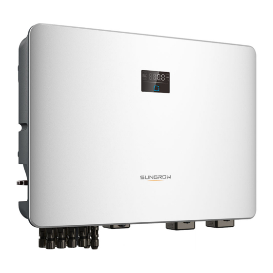
2 Product Description Product Introduction Model Description The model description is as follows (take SH8.0RS as an example): Appearance The following figure shows the appearance of the inverter. The image shown here is for reference only. The actual product received may differ. - Page 20 2 Product Description User Manual figure 2-1 Inverter Appearance Description Name To safely disconnect the DC circuit whenever necessary. DC switch Hanger To hang the inverter on the wall-mounting bracket. The LED screen indicates the running information and the LED pannel LED indicator indicates the current working state of the inverter.
-
Page 21: Symbols On The Product
The following figure shows the dimensions of the inverter. figure 2-2 Dimensions of the Inverter W (mm) H (mm) D (mm) Inverter Model SH8.0RS / SH10RS Symbols on the Product Symbol Explanation DC parameters on the PV side. Parameters on the battery side. -
Page 22: Led Panel
2 Product Description User Manual Symbol Explanation UKCA mark of conformity. The inverter does not have a transformer. Do not dispose of the inverter together with household waste. Disconnect the inverter from all the external power sources be- fore maintenance! Danger to life due to high voltages! Read the user manual before maintenance! Burn danger due to the hot surface that may exceed 60℃. - Page 23 User Manual 2 Product Description Description Name E-day Today’s energy yield Real-time AC output power Battery SOC (State of Charge) To indicate the working state of the inverter. Touch it to switch the information in normal state or view multiple indicator error codes in error state.
-
Page 24: Dc Switch
2 Product Description User Manual table 2-1 State description of the LED indicator LED color State Definition The inverter is operating normally. The inverter is at standby or startup state (not Flashing feeding power into the grid). Blue A system fault has occured. Both the AC and DC sides are powered down. -
Page 25: Pv Energy Storage System (Pv Ess)
Description Item Note Compatible with monocrystalline silicon, polycrystalline sili- PV strings con, and thin-film modules without grounding. SH8.0RS, SH10RS Inverter Metering device Meter cupboard with power distribution system. Utility grid TT,TN-C,TN-S, TN-C-S. Common loads, which will be lack of power when grid is Loads blackout. -
Page 26: Declaration For Back-Up Function
PV modules and batteries. If there is no available power from batteries or PV modules in backup mode, the backup power supply will be automatically terminated. SUNGROW shall hold no liability for any consequences arising from failing to observe this instruction. -
Page 27: Retrofitting The Existing Pv System
User Manual 2 Product Description • Due to the condition of the battery itself, battery current might be limited by some factors, including but not limited to the temperature and weather. Declaration For Back-Up Overload Protection The inverter will restart in case of overload protection. The time required for restarting will in- crease (5 min at most)(10 min at most) if overload protection repeats. - Page 28 2 Product Description User Manual Retrofit the Existing PV Inverter(s) to the Hybrid Inverter Off-grid Port figure 2-7 Retrofit the Existing PV Inverter(s) to the Hybrid Inverter Off-grid Port The off-grid port retrofits the existing PV system in order to maximize the use of PV energy by allowing the PV inverter to work even when off-grid.
-
Page 29: Function Description
Function Description Safety Function 3.1.1 Protection Several protective functions are integrated in the inverter, including short circuit protection, grounding insulation resistance surveillance, residual current protection, anti-islanding pro- tection, DC overvoltage / over-current protection, etc. 3.1.2 Earth Fault Alarm The device gives an alarm if there is a grounding fault. If the AC side is poorly grounded or not grounded, the buzzer rings, and the LED indicator turns red. -
Page 30: Drm ("Au"/"Nz")
3 Function Description User Manual • grid over-voltage • grid over-frequency • power factor (when values out of the rated values) • over-temperature (including ambient temperature and module temperature) • grid under-voltage • power factor (when values out of the rated values) •... -
Page 31: Regular Operational Frequency Range
The reactive power regulation mode can be set via the iSolar- Cloud App. Battery Management Li-ion battery from SUNGROW and BYD are compatible with the PV ESS,further battery models will be made compatible in the furture. The currently supported battery brands and models are shown in the following table. - Page 32 3-2 Battery Status Definition Port Voltage / SOC Type Empty Normal Full SUNGROW 5 %...100 % (SBR096/128/160/ SOC < 5 % SOC = 100 % (by default) 192) BYD (Battery-Box 5 %...100 %)
-
Page 33: Charge Management
The emergency charge command reported to the inverter is cleared. table 3-4 Default SOC Conditions for Li-ion Battery Backup Charge Type Trigger SOC Finishing SOC SUNGROW SOC ≤ 2 % SOC ≥ 4 % LG Chem SOC ≤ 5 % SOC ≥... -
Page 34: Discharge Management
3 Function Description User Manual Normal Charge Management When the battery voltage is within the normal range, the inverter can charge the battery if the PV power is higher than the load power and can ensure that the battery is never over- charged. -
Page 35: Communication And Configuration
User Manual 3 Function Description figure 3-1 PID Recovery Scheme • The PID recovery function is inapplicable to N-type panel, please disable it; • About 20W is consumed during PID recovery at night. Keep the DC switch "ON" in the PID recovery process. During the process, there is voltage hazard between inverter / PV module live conductors and ground. -
Page 36: Unpacking And Storage
• Check the inner contents for damage after unpacking. Contact SUNGROW or the transport company in case of any damage or incompleteness, and provide photos to facilitate services. Do not dispose of the original packing case. It is recommended to store the device in the original packing case when the product is decommissioned. - Page 37 User Manual 4 Unpacking and Storage • If the inverter needs to be transported again, pack it strictly before loading and transport- ing it. • Do not store the inverter in places susceptible to direct sunlight, rain, and strong electric field.
-
Page 38: Mechanical Mounting
Mechanical Mounting Respect all local standards and requirements during mechanical installation. Safety During Mounting Make sure there is no electrical connection before installation. Before drilling, avoid the water and electricity wiring in the wall. Poor installation environment will affect system performance! •... -
Page 39: Location Requirements
User Manual 5 Mechanical Mounting Location Requirements To a large extent, a proper installation location ensures safe operation, service life, and per- formance of the inverter. • The inverter with protection rating IP65 can be installed both indoors and outdoors. •... - Page 40 5 Mechanical Mounting User Manual...
-
Page 41: Environment Requirements
User Manual 5 Mechanical Mounting 5.2.1 Environment Requirements • The installation environment must be free of inflammable or explosive materials. • The location should not be accessible to children. • The ambient temperature and relative humidity must meet the following requirements. - Page 42 • Please consult SUNGROW before installing inverters outdoors in salt stress areas. Salt stress areas mainly refer to coastal areas that are within 500 meters from the coast. The deposition of salt fog varies largely with nearby seawater characteristics, sea wind, pre- cipitation, relative humidity, terrain, and forest coverage.
-
Page 43: Carrier Requirements
User Manual 5 Mechanical Mounting • Inverters should not be installed in coastal areas with high salt spray and desert areas. 5.2.2 Carrier Requirements The mounting structure where the inverter is installed must comply with local/national stand- ards and guidelines. Ensure that the installation surface is solid enough to bear four times the weight of the inverter and is suitable for the dimensions of the inverter (e.g. - Page 44 5 Mechanical Mounting User Manual...
- Page 45 User Manual 5 Mechanical Mounting...
-
Page 46: Angle Requirements
Install the inverter vertically or at the maximum allowable rear tilt angle. Do not install the in- verter horizontally, forward, excessively backward, sideways, or upside down. Please consult SUNGROW before tilting backwards the inverter and install it in floating power plants. - Page 47 User Manual 5 Mechanical Mounting...
- Page 48 5 Mechanical Mounting User Manual...
- Page 49 User Manual 5 Mechanical Mounting In case the installation site is a level surface, mount the inverter to the bracket to meet the mounting angle requirements, as shown in the figure below.
-
Page 50: Clearance Requirements
5 Mechanical Mounting User Manual Take the following items into account when designing the bracket scheme: • Consider onsite climate conditions and take anti-snow and anti-rain measures if necessary. • Ensure that the waterproof connectors are at least 300mm higher than the ground surface. - Page 51 User Manual 5 Mechanical Mounting...
- Page 52 5 Mechanical Mounting User Manual...
- Page 53 User Manual 5 Mechanical Mounting * In case this distance is less than the distance in the diagram, move the inverter from the mounting-bracket or wall before maintaining fans.
- Page 54 5 Mechanical Mounting User Manual The distance between the bottom of the inverter and the ground surface is deter- mined according to the bending radius of the AC cable used and the installation environment. In addition, the following conditions must be met: •...
- Page 55 User Manual 5 Mechanical Mounting The distance between the bottom of the inverter and the ground surface is deter- mined according to the bending radius of the AC cable used and the installation environment. In addition, the following conditions must be met: •...
- Page 56 5 Mechanical Mounting User Manual • The AC cable should be led into the inverter vertically with a vertical length of no less than 200mm. In case of multiple inverters, reserve specific clearance between the inverters. For other in- stallation scenarios, please refer to the relevant technical documents on http://support.sun- growpower.com/.
- Page 57 User Manual 5 Mechanical Mounting In case of back-to-back installation, reserve specific clearance between the two inverters.
- Page 58 5 Mechanical Mounting User Manual In case of back-to-back installation, reserve specific clearance between the two inverters. In case of back-to-back installation, reserve specific clearance between the two inverters. Install the inverter at an appropriate height for ease of viewing LED indicator and operating switch(es).
-
Page 59: Installation Tools
User Manual 5 Mechanical Mounting should be placed horizontally between two inverters and should not block the air outlet of inverters. Installation Tools Installation tools include but are not limited to the following recommended ones. If necessary, use other auxiliary tools on site. table 5-1 Tool specification Goggles Earplugs... -
Page 60: Moving The Inverter
5 Mechanical Mounting User Manual Wire cutter Wire stripper Hydraulic plier RJ45 crimping tool MC4 terminal Tube terminal Electric screwdriver Hammer drill (φ10) crimping tool (0.5 (M4, M5, M6) crimping tool (4 –6 mm –1.0 mm Phillips screwdriver Vacuum cleaner Measuring tape Heat shrink tubing (M4) -
Page 61: Installing The Inverter
User Manual 5 Mechanical Mounting • Lift the inverter using the handles positioned on both sides of the inverter. • Move the inverter by one or two people or by using a proper transport tool. • Do not release the equipment unless it has been firmly secured. Improper handling may cause personal injury! •... - Page 62 5 Mechanical Mounting User Manual * The image shown here is for reference only. The actual product received may differ. Inverter Model L1 (mm) L2 (mm) H (mm) SG2.0RS-S, SG2.5RS-S, SG3.0RS-S SG3.0RS, SG3.6RS, SG4.0RS, SG5.0RS, SG6.0RS step 2 Place the expansion tubes into the holes. Then secure the wall-mounting bracket to the wall firmly with the expansion bolt sets.
- Page 63 User Manual 5 Mechanical Mounting step 3 Lift the inverter and slide it down along the wall-mounting bracket to make sure they match perfectly. Use two screw sets to lock both left and right sides.
- Page 64 5 Mechanical Mounting User Manual - - End...
-
Page 65: Electrical Connection
Electrical Connection Safety Instructions The PV string will generate lethal high voltage when exposed to sunlight. • Operators must wear proper personal protective equipment during electrical connections. • Must ensure that cables are voltage-free with a measuring instrument before touching DC cables. •... - Page 66 6 Electrical Connection User Manual All electrical connections must comply with local and national/regional electrical standards. • Cables used by the user shall comply with the requirements of local laws and regulations. • Only with the permission of the national/regional grid department, the inverter can be connected to the grid.
-
Page 67: Terminal Description
User Manual 6 Electrical Connection The cable colors in figures in this manual are for reference only. Please select ca- bles according to local cable standards. Terminal Description All electrical terminals are located at the bottom of the inverter. figure 6-1 Terminals * The image shown here is for reference only. -
Page 68: Electrical Connection Overview
For inverter daisy chain (Reserved) A1, B1 RS485 For Li-ion battery communication via RS485 protocol. RSD-1, Reserved (Detail availability contact SUNGROW) RSD-2 EN_H, EN_ Enable the battery with a voltage of 12V. Enable For external Demand Response Enabling Device ("AU"/ D1/5, D2/6, "NZ") - Page 69 User Manual 6 Electrical Connection (A) Router (B) Battery (C) PV string (D) Inverter (E) AC circuit breaker (F) Smart energy meter (G) Grid (H) Backup loads (I) Monitoring device table 6-3 Cable Requirements Type Cable Cable Diameter Cross-section CAT 5E outdoor Ethernet shielded network 4.8 –...
-
Page 70: Backup Wiring Diagram
6 Electrical Connection User Manual Backup Wiring Diagram For AU/NZ/SA For Australia, New Zealand and South Africa, the neutral cable of GRID side and BACK-UP side must be connected together. Otherwise BACK-UP function will not work. SH8.0/10RS ① 40A/600V DC breaker * ②... - Page 71 User Manual 6 Electrical Connection SH8.0/10RS ① 40A/600V DC breaker * ② ≤63A/230V/400V AC breaker ③ 32A/230V/400V AC breaker ④ Depends on loads ⑤ Depends on household loads and inverter capacity (Optional) ⑥⑦ 30mA RCD (Recommended) ⑧ 300mA RCD (Recommended) Note 1: * If the battery is integrated with a readily accessible internal DC breaker, no addi- tional DC breaker is required.
-
Page 72: External Protective Grounding Connection
6 Electrical Connection User Manual SH8.0/10RS ① 40A/600V DC breaker * ② ≤63A/230V/400V AC breaker ③ 32A/230V/400V AC breaker ④ Depends on loads ⑤ Depends on household loads and inverter capacity (Optional) ⑥⑦ 30mA RCD (Recommended) ⑧ 300mA RCD (Recommended) Note 1: * If the battery is integrated with a readily accessible internal DC breaker, no addi- tional DC breaker is required. -
Page 73: External Protective Grounding Requirements
AC side grounding terminal are reliably grounded. The grounding connection can be made by other means if they are in accordance with the local standards and regulations, and SUNGROW shall not be held liable for the possible consequences. - Page 74 6 Electrical Connection User Manual External grounding cable and OT/DT terminal are prepared by customers. step 1 Prepare the cable and OT/DT terminal. (1) Heat shrink tubing (2) OT/DT terminal After being crimped, the OT terminal must wrap the wires completely, and the wires must contact the OT terminal closely.
-
Page 75: Ac Cable Connection
User Manual 6 Electrical Connection step 3 Apply paint to the grounding terminal to ensure corrosion resistance. - - End AC Cable Connection 6.6.1 AC Side Requirements Only with the permission of the local grid department, the inverter can be con- nected to the grid. - Page 76 6 Electrical Connection User Manual Recommended Specifica- Recommended Specifica- Inverter Model tion (back-up) tion (on-grid) SH8.0/10RS 32 A ≤ 63 A Testing to AS/NNZS 4777.2:2020 Section for multiple phase combinations has not been conducted. AC circuit breakers should be installed on the output side of the inverter and the grid side to ensure safe disconnection from the grid.
-
Page 77: Connecting The Ac Cable
Multiple Inverters in parallel Connection If multiple inverters are connected in parallel to the grid, ensure that the total number of par- allel inverters does not exceed 5. Otherwise, please contact SUNGROW for technical scheme. 6.6.2 Connecting the AC Cable step 1 Disconnect the AC circuit breaker and secure it against reconnection. - Page 78 6 Electrical Connection User Manual step 6 Remove the waterproof lid from the GRID terminal. step 7 Fix all the wires to the terminals according to the assignment and tighten to a torque of 2.0 N•m with a screwdriver. Observe the terminal assignment. Do not connect any phase line to the "PE" termi- nal or PE wire to "N"...
-
Page 79: Dc Cable Connection
User Manual 6 Electrical Connection step 8 Secure the AC waterproof cover to the inverter with a torque of 1.2 N•m and tighten the swiv- el nut to a torque of 5 N•m–6 N•m. step 9 Connect the PE wire to ground and the phase lines and the “N” line to AC circuit breaker. Then connect the AC circuit breaker to electric board. - Page 80 6 Electrical Connection User Manual • Make sure the PV array is well insulated to ground before connecting it to the inverter. • Make sure the maximum DC voltage and the maximum short circuit current of any string never exceed inverter permitted values specified in "Technical Data". •...
-
Page 81: Pv Input Configuration
User Manual 6 Electrical Connection The following requirements about PV string connection must be met. Otherwise, it may cause irreversible damage to the inverter, which is not covered by the warranty. • Mixed use of PV modules of different brands or models in one MPPT circuit, or PV modules of different orientation or inclination in a string may not damage in- verter, but will cause system bad performance! •... -
Page 82: Assembling The Pv Connectors
6 Electrical Connection User Manual • The PV strings to two DC input areas may differ from each other, including PV module type, number of PV modules in each string, angle of tilt, and installation orientation. figure 6-3 PV Input Configuratinon Prior to connecting the inverter to PV inputs, the following electrical specifications must be met simultaneously: Open-circuit Voltage Limit... -
Page 83: Installing Pv Connector
User Manual 6 Electrical Connection 1: Positive crimp contact 2: Negative crimp contact step 3 Lead the cable through cable gland, and insert the crimp contact into the insulator until it snaps into place. Gently pull the cable backward to ensure firm connection. Tighten the ca- ble gland and the insulator (torque 2.5 N.m to 3 N.m). - Page 84 6 Electrical Connection User Manual step 2 Check the cable connection of the PV string for polarity correctness and ensure that the open circuit voltage in any case does not exceed the inverter input limit of 1,000V1,100V600V.
- Page 85 4 Follow the foregoing steps to connect PV connectors of other PV strings. step 5 Seal any unused PV terminal with a terminal cap. SUNGROW inverters cannot be used with third-party optimizers. If the PV string is equipped with the optimizer, please refer to the optimizer manual for elec- trical connections and make sure that the polarity of the optimizer cables is correct.
-
Page 86: Emergency Load Connection (Backup)
Do not short-circuit the Backup port during operation. Otherwise, the inverter or power distribution system will be seriously damaged. The loss is not covered by the SUNGROW warranty. step 1 Unscrew the swivel nut of the AC connector. step 2 Thread the AC cable of appropriate length through the swivel nut, the sealing ring and the housing. - Page 87 User Manual 6 Electrical Connection step 4 Open the clamp on the spring-loaded terminal and fully insert the wires into the correspond- ing holes. Then close the clamp and push the terminal plug into the housing until there is an audible click.
-
Page 88: Battery Connection
6 Electrical Connection User Manual step 7 Lift the locking part upwards and insert the AC connector into the BACKUP terminal on the bottom side of the inverter. Then press the locking part and lock it with the screw. step 8 Connect the other ends to the emergency loads. Pull all the lines outward lightly to check whether they are firmly installed. -
Page 89: Connecting The Power Cable
User Manual 6 Electrical Connection Do not disconnect under load! Battery connectors must not be disconnected while under load. They can be placed in a no load state by shutting down the inverter completely. During the installation and operation of the inverter, please ensure that the positive or negative polarities of batteries do not short-circuit to the ground. - Page 90 6 Electrical Connection User Manual step 3 Lead the cable through cable gland, and insert the crimp contact into the insulator until it snaps into place. Gently pull the cable backward to ensure firm connection. step 4 Tighten the cable gland and the insulator. step 5 Check for polarity correctness.
- Page 91 User Manual 6 Electrical Connection step 2 Ensure that the connectors are securely in place. - - End 6.9.1.3 Assembling Evo2 Compatible Connector The connector type is subject to the actual received device. step 1 Strip 15 mm of the insulation layer from each PV cable. step 2 Unscrew the swivel nut of the connector.
-
Page 92: Connecting The Can Cable
2 Check for polarity correctness. - - End 6.9.2 Connecting the CAN Cable The CAN cable enables the communication between the inverter and the Li-ion battery from SUNGROW and BYD. • Pin terminal connection Refer to the section "6.11 Meter Connection"... -
Page 93: Connecting The Enable Cable
User Manual 6 Electrical Connection Refer to the section "6.13 DRM Connection" for details. Plug the wires into the RJ45–CAN terminal on the bottom of the inverter. 6.9.3 Connecting the Enable Cable The Enable cable along with the RS485 cable, are used for communication between the in- verter and the Li-ion battery. -
Page 94: Ethernet Communication
6 Electrical Connection User Manual 6.10.1 Ethernet Communication The WiNet-S communication for Ethernet cannot be used simultaneously with A1 and B1 terminals for RS485 daisy chain. step 1 (Optional) Strip the insulation layer of the communication cable with an Ethernet wire strip- per, and lead the corresponding signal cables out. - Page 95 User Manual 6 Electrical Connection step 4 Thread the network cable through the swivel nut and gasket. Afterwards, route the cable into the opening of the sealing. Finally, insert the cable through the housing. step 5 Insert the RJ45 plug into the front plug connector until there is an audible click and tighten the housing.
- Page 96 6 Electrical Connection User Manual...
-
Page 97: Wlan Communication
User Manual 6 Electrical Connection step 7 Slightly shake it by hand to determine whether it is installed firmly. - - End 6.10.2 WLAN Communication step 1 Remove the waterproof lid from the COM1 WLAN terminal. step 2 Install the module. Slightly shake it by hand to determine whether it is installed firmly, as shown below. - Page 98 6 Electrical Connection User Manual...
-
Page 99: Meter Connection
User Manual 6 Electrical Connection step 3 Refer to the guide delivered with the module for the set-up. - - End 6.11 Meter Connection The inverter can provide export control but will require the use of a external smart meter. The export control functionality has not been tested to AS/NZS 4777.2:2020. - Page 100 6 Electrical Connection User Manual step 1 Remove the cable jacket and strip the wire insulation. step 2 (Optional) When using a multi-strand wire cable, connect the wire head to the cord end ter- minal. In case of single-strand copper wire, skip this step. step 3 Unscrew the swivel nut from the connector.
- Page 101 User Manual 6 Electrical Connection step 5 Plug the wires into the corresponding terminals as shown in the following figure. Ensure that the wires are securely in place by slightly pulling them. step 6 Remove the waterproof lid from the COM2 terminal.
-
Page 102: Rs485 Connection
6 Electrical Connection User Manual step 7 Insert the terminal plug into the COM2 terminal at the bottom side of the inverter and then in- stall the housing. step 8 Slightly pull out the cable and then fasten the swivel nut. Lock the connector with the screw. - - End 6.12 RS485 Connection The RS485 connection is reserved for inverter daisy chain. - Page 103 User Manual 6 Electrical Connection table 6-4 Method of Asserting DRM Asserted by Shorting Terminals Switch Operation on External Mode on Inverter DRED DRM0 R & C Close S1 and S5 DRM1 D1/5 & C Close S1 DRM2 D2/6 & C Close S2 DRM3 D3/7 &...
- Page 104 6 Electrical Connection User Manual 1: RJ45 plug 2:Protective cap Skip this step if a standard network cable with RJ45 plug is prepared. step 2 Unscrew the swivel nut from the connector. step 3 Remove the seal.
- Page 105 User Manual 6 Electrical Connection step 4 Lead the cable through the cable gland. step 5 Plug the wires into the corresponding terminals as shown in the following figure. Ensure that the wires are securely in place by slightly pulling them. step 6 Slightly pull out the cable and then fasten the swivel nut.
-
Page 106: Commissioning
Commissioning Inspection Before Commissioning Check the following items before starting the inverter: • All equipment has been reliably installed. • DC switch(es) and AC circuit breaker are in the "OFF" position. • The ground cable is properly and reliably connected. •... -
Page 107: App Preparation
"8.3 Account Registration". If you have got the account and password from the distributor/installer or SUNGROW, skip this step. step 3 Download the firmware package to the mobile device in advance. Refer to “Firmware Upa- date”. This is to avoid download failure due to poor on-site network signal. - Page 108 7 Commissioning User Manual step 4 Fill in the content according to actual needs, and the parameters containing * are required. Tap Next to enter the next interface. figure 7-2 Plant Creation Settings Parameter Description Name Plant name The name of the plant. Plant type The type of the plant, which should be set corresponding to the actual plant type.
- Page 109 User Manual 7 Commissioning Parameter Description Name Time zone The time zone where the plant is located, which can be filled through automatic positioning and manual input. The location of the plant, which can be filled in two ways: • Manually: Manually enter the plant location in the input box.
- Page 110 7 Commissioning User Manual step 6 After a device is bound, tap Device and Commissioning to go to corresponding interface. step 7 Tap Network Configuration to go to the WLAN connection interface. Tap the home net- work in the WLAN list, enter the password, and then tap Confirm.
- Page 111 User Manual 7 Commissioning step 8 Enter the Activate EasyConnect interface, and press the multi-function button on the WiNet-S to enable the Easyconnect mode according to the prompt on the screen. The App automatically enters a waiting processing interface if this mode is enabled, and automatically returns to the commissioning interface after the processing is completed.
- Page 112 7 Commissioning User Manual When the country is set to Australia, additionally set the applicable network service provider and then the grid type. The image shown here is for reference only. Refer to the actual interface for the supported network service providers.
- Page 113 User Manual 7 Commissioning table 7-1 Description of Network Service Provider and Grid Type Network Service Provider Grid Type AS/NZS 4777.2:2015 AS/NZS 4777.2:2020 Australia A AS/NZS 4777.2:2020 Australia B AS/NZS 4777.2:2020 Australia C • STNW1170: single-phase < 10 kVA & ENERGEX &...
- Page 114 7 Commissioning User Manual • Please check the country supported by this product at http:// support.sungrow- power.com/. • Set Country/Region to the country/region where the inverter is installed. Oth- erwise, the inverter may report a fault. • For the commissioning process – country code must be selected before the in- verter can operate.
-
Page 115: Isolarcloud App
App. * To achieve direct login via WLAN, the wireless communication module developed and manufactured by SUNGROW is required. The iSolarCloud App can also establish communi- cation connection to the inverter via Ethernet connection. -
Page 116: Account Registration
8 iSolarCloud App User Manual Account Registration The account distinguishes two user groups, end user and distributor/installer. • The end user can view plant information, create plants, set parameters, share plants, etc. • The distributor/installer can help the end user to create plants, manage, install, or main- tain plants, and manage users and organizations. -
Page 117: Login
User Manual 8 iSolarCloud App step 4 Fill in the registration information, including email, verification code, password and affirm- ance and country (region). The distributor/installer has the permission to fill in the company name and the code of upper level installer/distributor. The code of upper level distributor/installer can be obtained from the upper level distributor/installer. - Page 118 8 iSolarCloud App User Manual figure 8-1 Enabling the WLAN Hotspot step 2 Connect the mobile phone to the WLAN network named as "SG-xxxxxxxxxxx" (xxxxxxxxxxx is the serial number indicated on the side of the communication module). step 3 Open the App to enter the login screen. Tap Local Access to enter the next screen. step 4 Tap Confirm, then enter the password and tap LOGIN.Or tap MANUAL CONNECTION at the bottom of the interface and select WiNet-S, then enter the password and tap LOGIN.
-
Page 119: Initial Settings
User Manual 8 iSolarCloud App figure 8-3 WLAN Local Access step 6 After finishing the settings, tap TUNR ON DEVICE at the upper right corner and the device will be initialized. The App will send start instructions and the device will start and operate. step 7 After initialization settings, the App will return automatically to the home page. -
Page 120: Function Overview
8 iSolarCloud App User Manual Function Overview The App provides parameter viewing and setting functions, as shown in the following figure. figure 8-4 App Function Tree Map Home Home page of the App is shown in the following figure. - Page 121 User Manual 8 iSolarCloud App figure 8-5 Home figure 8-6 Home table 8-2 Home page description Description Name Shows the PV power generation power, feed-in power, etc. The line with an arrow indicates energy Load flow chart flow between connected devices, and the arrow pointing indicates energy flow direction.
-
Page 122: Run Information
8 iSolarCloud App User Manual Description Name Today yield Shows today power generation of the inverter Direct Power Con- Shows electricity directly consumed by loads today sumption of Today Battery SOC Indicates remaining battery capacity Today Self-consu Indicates today self-consumption rate of the PV Rate system Includes menus of Home, Run Information, Re-... -
Page 123: Chart
User Manual 8 iSolarCloud App figure 8-8 Records On Records screen, users can view chart and check fault alarm record. 8.9.1 Chart Tap Chart to enter the screen showing daily power generation, as shown in the following figure. figure 8-9 Power Curve The App displays power generation records in a variety of forms, including daily power gen- eration graph, monthly power generation histogram, annual power generation histogram, and total power generation histogram. -
Page 124: Fault Alarm Record
8 iSolarCloud App User Manual Item Description Annual power generation Indicates annual power generation, charging, feed-in power, histogram and direct consumption power Total power generation Indicates total power generation, charging, feed-in power, histogram and direct consumption power 8.9.2 Fault Alarm Record Tap Fault Alarm Record to enter the screen, as shown in the following figure. -
Page 125: More
User Manual 8 iSolarCloud App figure 8-12 Event Record Click to select a time segment and view corresponding records. 8.10 More Tap More on the navigation bar to enter the screen, as shown in the following figure. figure 8-13 More... -
Page 126: System Parameters
8 iSolarCloud App User Manual figure 8-14 More The More screen supports the following operations: • Set parameters including inverter system parameters and energy management parameter. • Upgrade inverter firmware of the communication module. 8.10.1 System Parameters Tap Settings→System Parameters to enter the corresponding interface, as shown in the following figure. -
Page 127: Running Time
User Manual 8 iSolarCloud App Boot/Shutdown Tap Boot/Shutdown to send the boot/shutdown instruction to the inverter. For Australia and New Zealand, when the DRM state is DRM0, the "Boot" option will be prohibited. Date Setting/Time Setting The correct system time is very important. Wrong system time will directly affect the data logging and power generation value. -
Page 128: Off-Grid Parameters
8 iSolarCloud App User Manual table 8-5 The control mode of DO configuration Setting description Mode Grounding Detection "8.10.11 Grounding Detection" 8.10.4 Off-grid Parameters Tap Settings→Operation Parameters→Off-grid Parameters to enter the screen, as shown in the following figure. figure 8-18 Off-grid Parameters Refer to the description in "8.5.2 Backup Mode"... -
Page 129: Reactive Power Regulation
User Manual 8 iSolarCloud App figure 8-19 Active Power Regulation table 8-6 Description of active power regulation Description Range Parameter Default Switch for activating/deactivating the Active Power Soft function of active power soft start after On/Off Start after Fault a fault occurs Active Power Soft The soft start time required for raising Start Time after... - Page 130 8 iSolarCloud App User Manual figure 8-20 Reactive Power Regulation table 8-7 Description of reactive power regulation Description Range Parameter Default Switch for activating/deactivating the Reactive Power function of reactive power setting Setting On / Off persistence Persistence Off / PF / Reactive Power Qt / Q(P) / Regulation Mode...
- Page 131 User Manual 8 iSolarCloud App “Q(P)” Mode The PF of the inverter output varies in response to the output power of the inverter. table 8-9 “Q(P)” Mode Parameter Descriptions: Explanation Range Parameter Select corresponding curve according to Q(P) Curve A, B, C local regulations Output power at P1 on the Q(P) mode QP_P1...
- Page 132 8 iSolarCloud App User Manual table 8-10 “Q(U)” Mode Parameter Descriptions: Explanation Range Parameter Select corresponding curve according to lo- Q(U) curve A, B, C cal regulations Voltage hysteresis ratio on the Q(U) mode Hysteresis Ratio 0 ~ 5% curve Grid voltage limit at P1 on the Q(U) mode QU_V1 77% ~ 123%...
-
Page 133: Battery Discharge Time
User Manual 8 iSolarCloud App figure 8-22 Q(U) Curve 8.10.7 Battery Discharge Time Tap Settings→Energy Management Parameter→Battery Discharge Time to enter the corresponding screen, as shown in the following figure. These are the times of day at which the battery is allowed to discharge to the house loads. figure 8-23 Battery Discharge Time 8.10.8 Battery Forced Charge Time Tap Settings→Energy Management Parameter→Battery Forced Charge Time to enter... -
Page 134: Communication Parameters
8 iSolarCloud App User Manual figure 8-24 Battery Forced Charge Time When there is no PV power, the power imported from the grid charges the energy system during the time period until the target SOC is reached. It is recommended to set the time period in off-peak tariff time. The time period 1 is in priority to the time period 2 if two periods overlap. -
Page 135: Firmware Update
User Manual 8 iSolarCloud App figure 8-25 Communication Parameters figure 8-26 Communication Parameters • The device address ranges from 1 to 246. • The IP adress, gateway, subnet mask, preferred DNS server and alternate DNS server can be modified only when the DHCP is set to Off. •... -
Page 136: Grounding Detection
If the distributor is unable to provide the required information, contact SUNGROW. Unauthorized personnel are not allowed to log in with this account. Otherwise, SUNGROW shall not be held liable for any damages caused. Tap More→Settings→Operation Parameters→Grounding Detection to enter the corre- sponding screen. -
Page 137: Frequency Shift Power Control
User Manual 8 iSolarCloud App figure 8-27 Grounding Detection If the grounding detection is enabled, the DO relay will switch on automatically to signal the external alarm if the value exceeds the grounding detection alarm value. The buzzer inside the inverter will beep. The PV insulation resistance fault (fault sub-code 039) will trigger the DO relay to signal the external alarm. -
Page 138: Import Power Limit
8 iSolarCloud App User Manual 8.10.13 Import Power Limit Import power is the sum of the battery charging power and the load power of the Backup. Following local regulations, calculate the maximum system tolerable power based on the wire and circuit breaker that required by the selected model, and the value can be set as the Import Power Limit. -
Page 139: System Decommissioning
System Decommissioning Decommissioning the Inverter 9.1.1 Disconnecting Inverter Danger of burns! Even if the inverter is shut down, it may still be hot and cause burns. Wear protec- tive gloves before operating the inverter after it cools down. For maintenance or other service work, the inverter must be switched off. Proceed as follows to disconnect the inverter from the AC and DC power sources. -
Page 140: Disposal Of Inverter
9 System Decommissioning User Manual step 1 Refer to "6 Electrical Connection" for the inverter disconnection of all cables in reverse steps. step 2 Dismantle the inverter referring to "5 Mechanical Mounting" in reverse steps. step 3 If necessary, remove the wall-mounting bracket from the wall. step 4 If the inverter will be reinstalled in the future, please refer to "4.2 Inverter Storage"... -
Page 141: Troubleshooting And Maintenance
App or the LCD. Modify the overvoltage protection values with the consent of the local electric power operator. 3. If the fault still exists, contact SUNGROW. Generally, the inverter will be reconnected to the grid after the grid returns to normal. If the fault occurs repeatedly: 1. - Page 142 2. Check whether the protection parameters are ap- propriately set via the App or the LCD. 3. If the fault still exists, contact SUNGROW. Generally, the inverter will be reconnected to the grid after the grid returns to normal. If the fault occurs repeatedly: 1.
- Page 143 App or the LCD. 3. If the fault still exists, contact SUNGROW. 1. Check whether the corresponding string is of re- verse polarity. If so, disconnect the DC switch and ad- just the polarity when the string current drops below 0.5 A.
- Page 144 PV Abnormal so, make it reliably connected. 580-595 Alarm 3. If the alarm still exists, contact SUNGROW. *The code 548 to code 563 are corresponding to string 1 to string 16 respectively. *The code 580 to code 595 are corresponding to string 17 to string 32 respectively.
- Page 145 If so, replace the damaged cable and secure terminals to ensure a reliable connection. 5. If the fault still exists, contact SUNGROW. 1. Check whether the AC cable is correctly connected. 2. Check whether the insulation between the ground Grounding Cable cable and the live wire is normal.
- Page 146 1. Check whether the output port is connected to ac- Grid tual grid. Disconnect it from the grid if so. Confrontation 2. If the fault still exists, contact SUNGROW. 1. Check whether the communication cable and the terminals are abnormal. If so, correct them to ensure Inverter Parallel reliable connection.
- Page 147 System Fault 248–255, Close the AC and DC switches in turn 15 minutes lat- 300–322, er and restart the system. 324–328, 3. If the fault still exists, contact SUNGROW. 401–412, 600–603, 605, 608, 612, 616, 620, 622– 624, 800, 802, 804, 807, 1096–...
- Page 148 MPPT Reverse 0.5 A. 264-283 Connection 2. If the fault still exists, contact SUNGROW. *The code 264 to code 279 are corresponding to string 1 to string 20 respectively. 1. The inverter can continue running. 2. Check whether the related wiring and terminals are...
-
Page 149: Maintenance
4. If the fault is not caused by the foregoing reasons and still exists, contact Sungrow Customer Service. 1. It is prohibited to disconnect the DC switch when the DC current is greater than 0.5 A when the fault occurs. - Page 150 To avoid the risk of electric shock, do not perform any other maintenance opera- tions beyond those described in this manual. If necessary, contact your distributor first. If the problem persists, contact SUNGROW. Otherwise, the losses caused is not covered by the warranty.
-
Page 151: Routine Maintenance
User Manual 10 Troubleshooting and Maintenance 10.2.2 Routine Maintenance Item Method Period Six months to a year Check the temperature and dust of the inverter. Clean the inverter enclosure if Device clean (depending on the dust con- necessary. tents in air) Check whether all cable are firmly con- nected in place. - Page 152 10 Troubleshooting and Maintenance User Manual Item Method Period Check whether cables are loose or fall off. Electrical Six months to a year Check whether the cable is damaged, connection especially the part in contact with the metal enclosure. Perform inspection and weeding be- fore vegetation wilts.
- Page 153 User Manual 10 Troubleshooting and Maintenance Item Method Period • Visual check for any damage or defor- mation of the inverter. • Check any abnormal noise during the General status of operation. Every 6 months the system • Check each operation parameter. •...
-
Page 154: Appendix
11 Appendix 11.1 Technical Data Parameter SH8.0RS SH10RS Input (DC) Recommended max. PV input 16000 Wp 20000 Wp power Max. PV input voltage 600 V Min. operating PV voltage / Start- 40 V / 50 V up input voltage Rated PV input voltage... - Page 155 User Manual 11 Appendix Parameter SH8.0RS SH10RS > 0.99 at default value at rated power Power factor at rated power / Ad- (adj. 0.8 overexcited / leading to 0.8 underexcited / justable power factor lagging) Feed-in phases / connection 1 / 1...
-
Page 156: Quality Assurance
• The customer shall give SUNGROW a reasonable period to repair the faulty device. Exclusion of Liability In the following circumstances, SUNGROW has the right to refuse to honor the quality guarantee: • The free warranty period for the whole machine/components has expired. -
Page 157: Contact Information
The fault or damage is caused by installation, repairs, modification, or disassembly per- formed by a service provider or personnel not from SUNGROW. • The fault or damage is caused by the use of non-standard or non-SUNGROW compo- nents or software. •...
Need help?
Do you have a question about the SH8.0RS and is the answer not in the manual?
Questions and answers