
Related Manuals for Sungrow SH3K6


Summary of Contents for Sungrow SH3K6
- Page 1 User Manual SH3K6 / SH4K6 Grid-Connected Hybrid Inverter SH3.6_4.6K-UEN-Ver12-202003 Version:1.2...
- Page 3 Documents must be stored carefully and be available at all times. All rights to the content of this manual are owned by Sungrow Power Supply Co., Ltd. (hereinafter “SUNGROW”). No part of this document can be modified, distributed, reproduced or published in any form or by any means without prior written permission from SUNGROW.
- Page 4 Symbol Explanation Indicates a hazard with a low level of risk that, if not avoided, could result in minor or moderate injury. Indicates a situation that, if not avoided, could result in equipment or property damage. Indicates additional information, emphasized contents or tips that may be helpful, e.g.
-
Page 5: Table Of Contents
Contents About This Manual ..............I Safety ..................1 System Solution ..............6 PV Energy Storage System (PV ESS) ........11 Retrofitting the Existing PV System ......... 13 Function Description ............15 Safety Function ............... 15 3.1.1 Protection ................15 3.1.2 Earth Fault Alarm ..............15 3.1.3 SPI and Auto Test (Italy only) .......... - Page 6 Safety during Mounting ............29 Location Requirements ............29 Tools ..................31 Installing the Inverter ..............33 Grounding the Inverter ............. 34 Installing the Energy Meter ............35 Electrical Connection ............36 Terminal Description ..............36 Energy Meter Connection ............38 Grid Connection ...............
- Page 7 Troubleshooting ............... 67 8.1.1 LED Indicator ................67 8.1.2 Errors on the App or LCD Screen ..........67 Maintenance ................76 8.2.1 Routine Maintenance .............. 76 8.2.2 Replacing the Button Cell ............76 System Decommissioning ..........77 Decommissioning the Inverter ..........77 Decommissioning the Battery ..........
- Page 8 11.1 For Countries except Italy ............94 11.1.1 “Qt” Mode ................94 11.1.2 “Q(P)” Mode ................94 11.1.3 “Q(U)” Mode ................95 11.1.4 Over-frequency Response ............ 96 11.2 For Italy (“IT”) ................97 11.2.1 “Qt” Mode ................97 11.2.2 “Q(P)” Mode ................98 11.2.3 “Q(U)”...
-
Page 9: Safety
1 Safety General Safety The inverter has been designed and tested strictly according to international safety regulations. Read all safety instructions carefully prior to any work and observe them at all times when working on or with the inverter. Incorrect operation or work may cause: ... - Page 10 1 Safety User Manual Symbol Explanation There is a danger from a hot surface that may exceed 60 ° C. Danger to life due to high voltages! Only qualified personnel can open and service the inverter. Check the user manual before service! Do not dispose of the inverter together with household wastes.
- Page 11 User Manual 1 Safety Risk of inverter damage or personal injury Do not pull out PV connectors, AC connector or battery connectors while the inverter is running. De-energize from all multiple power sources. Wait 10 minutes for the internal capacitors to discharge. Verify that there is no voltage or current before pulling any connector.
- Page 12 1 Safety User Manual Provide sufficient ventilation for lead-acid battery systems to prevent flames and sparks from the explosive hydrogen gas that the batteries release. Due to the dangers of hydrogen gas and battery electrolyte: locate batteries in a designated area, complying with the local regulations;...
- Page 13 User Manual 1 Safety Fire hazard If a fuse is missing or incorrect, a fire may be caused when a fault occurs. This can result in death or serious injury. Protect the line conductors of the Energy Meter with a fuse or a main/selective circuit breaker, max.
-
Page 14: System Solution
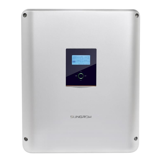
Any use other than that described in this document is not permitted. For the TT utility grid, the N line voltage to ground must be 30 V or less. SH3K6/SH4K6 is a single-phase hybrid inverter applicable to on-grid PV systems. With the integrated Energy Management System (EMS), it can control and optimize the energy flow in order to increase the self-consumption of the system. - Page 15 Grid Monitoring: VDE 0126-1-1 VDE-AR-N 4105 SUNGROW POWER SUPPLY CO., LTD. WWW.SUNGROWPOWER.COM MADE IN CHINA Fig. 2-1 Inverter Appearance Name Description AC-Grid AC terminal to the utility grid. Backup ctrl Reserved.
- Page 16 View or set parameters via the buttons. For detailed functions, Buttons see Tab. 7-1. Energy Meter The Sungrow Energy Meter is installed next to the main switch to detect the electrical measured values at the grid-connected point. It communicates with the inverter via an RS485 connection.
- Page 17 User Manual 2 System Solution Single-phase Energy Meter and its terminals are shown in the following figure. Designation Description 1, 4 For the 1-phase sensor 2 is for RS485-A 2, 5 5 is for RS485-B Stead on: the Energy Meter is powered on. Flashing: the Energy Meter is communicating with the PWR/COM inverter.
- Page 18 2 System Solution User Manual Three-phase Energy Meter and its terminals are shown in the following figure. Designation Specification 21, 22 RS485 communication terminals LCD screen Display active energy and reactive energy, etc. L1, L2, L3 Input terminals from grid side L1’, L2’, L3’, Output terminals to load side Neutral terminal...
-
Page 19: Pv Energy Storage System (Pv Ess)
Grid grounding system types: TT, TN Measures export power Sungrow single-phase or communicates with the inverter via the three-phase Energy Meter RS485 port. Inverter SH3K6 / SH4K6. Monocrystalline silicon, polycrystalline PV strings silicon, and thin-film without grounding. Household load Devices that consume energy. Battery (optional) A Li-ion battery or a lead-acid battery. - Page 20 2 System Solution User Manual If the PV power is less than the load power, the battery will discharge and provide the energy shortfall. The inverter will draw power from the mains if the power from the PV and battery is less than the load power. Energy Management during Night The battery discharges to provide energy to loads.
-
Page 21: Retrofitting The Existing Pv System
The power generation from the existing PV inverter will be firstly provided to the loads and then charge the battery. With the energy management function of the SH3K6 / SH4K6, the self-consumption of the new system will be greatly improved. - Page 22 2 System Solution User Manual PV inverter SH3K6/ SH4K6 Home appliance Fig. 2-7 Retrofitting the Existing PV System The existing PV inverter works as a load in the whole system but supply PV power to the 4600 2200 , as the power flow energy storage system shown on the main screen.
-
Page 23: Function Description
3 Function Description 3.1 Safety Function 3.1.1 Protection The protective functions are integrated in the inverter, including short circuit protection, grounding insulation resistance surveillance, residual current protection, anti-islanding protection, DC overvoltage / over-current protection, etc. 3.1.2 Earth Fault Alarm The inverter has integrated an earth fault dry-contact (DO2 relay) for the local alarm. -
Page 24: Energy Conversion And Management
3 Function Description User Manual 3.2 Energy Conversion and Management The inverter converts the DC power from the PV array or the battery to the AC power, which conforms to the grid requirements. It also transmits the DC power from the PV panel to the battery. With the bidirectional converter integrated inside, the inverter can charge or discharge the battery. -
Page 25: Regular Operational Voltage Range
User Manual 3 Function Description The following figure shows the under-voltage derating curve. Normally working area 230V Fig. 3-1 Grid Under-voltage Derating Export Power Limit Derating When the Energy Meter detects that the export power is greater than the limit value on the LCD, the inverter will reduce the output power within the specified range. - Page 26 3 Function Description User Manual voltage level goes back to normal levels after the disturbance. Condition 1: initial start-up Condition 2: reconnection after protection Normal operation Normal operation Reconnection Start-up Standby Standby Standby Standby Vmin V2 Vmax Vmin Vmax Grid voltage, V Grid voltage, V Fig.
-
Page 27: Regular Operational Frequency Range
User Manual 3 Function Description (1) 25 % Pn/min for initial connection and 10 % Pn/min for reconnection. (2) Not applicable for initial connection and 10 % Pn/min for reconnection. (3) 30 s for initial connection and 300 s for reconnection. 3.2.3 Regular Operational Frequency Range The inverter can operate within its frequency range for at least the specified observation time. -
Page 28: Active Power Regulation
3 Function Description User Manual IT (1) IT (0) Parameter F2 (Hz) 50.10 50.10 50.10 50.10 50.10 50.10 F3 (Hz) 47.50 47.50 47.50 48.00 49.50 47.50 F4 (Hz) 50.10 50.05 50.05 50.05 50.50 51.50 30 or 300 25 % Pn/min or Not applicable or 10 % 20 % Pn/min 10 % Pn/min... -
Page 29: Reactive Power Regulation
User Manual 3 Function Description Parameter Description Default Value Actual AC output power at the instance when the frequency reaches the Start frequency Active power increase rate relative to the 100% Pm/Hz Gradient actual power Pm per Hz The following figure shows the under-frequency response. Between the Start value and the End value, all adjustable power generation systems shall reduce (for frequency increase) or increase (for frequency decrease) the active power Pm generated instantaneously. -
Page 30: Load Control
The batteries compatible with the PV ESS must meet the IEC 62109 certification. The battery kinds are as follows. Li-ion battery from SUNGROW, LG Chem, GCL, Pylon, BYD and TAWAKI. Lead-acid battery which require manual configuration. The inverter is capable of managing the battery charging, discharging, and maintenance based on the battery status, which will maximize the battery life. -
Page 31: Charge Management
100 % Other lead-acid < 30 V Configured by the customer * The SOC limits of Li-ion batteries except Sungrow batteries can be modified via the iSolarCloud App or the iSolarCloud server by qualified personnel. 3.3.1 Charge Management Emergency Charge Management To avoid the damage caused by long time excessive discharge, ... -
Page 32: Discharge Management
User Manual Type Trigger Condition Finishing Condition SOC ≤ 2 % SOC ≥ 4 % SUNGROW (retrofitting system) SOC ≤ 2 % SOC ≥ 4 % LG (RESU G1/G2) SOC ≤ 12 % SOC ≥ 14 % SOC ≤ 17 % SOC ≥... -
Page 33: Battery Temperature Sensor (Pt1000)
User Manual 3 Function Description The maintenance process is as follows. Charge the battery with a constant current according to a C-rate of 0.165 C. C is the nominal capacity specified by the manufacturer and is indicated in Ah. Charge the battery with a trickle current when the battery voltage is stabilized at the average charge voltage. -
Page 34: Unpacking And Storing
Check the delivery contents for completeness according to the packaging list. Check the inner contents for any visible damage. Contact SUNGROW or the distributor in case of any damaged or missing components. It is the best choice to store the inverter in the original packaging. So, do not dispose of it. -
Page 35: Delivery Contents
User Manual 4 Unpacking and Storing 4.2 Delivery Contents Standard Delivery Expansion plug set (x2) Wall-mounting bracket Inverter AC connector set PV connectors Crimp contact Copper bar OT25-6 terminals M5 screw set CAN cable (battery) RS485 cable (meter) Documents Fig. 4-2 Delivery Contents Each set includes a self-tapping screw, a spring washer, a fender washer, and an expansion tube. -
Page 36: Storing The Inverter
4 Unpacking and Storing User Manual Single-phase meter Three-phase meter Wi-Fi module 4.3 Storing the Inverter If you do not install the inverter immediately, choose an appropriate location to store it. Instructions for storage are: The inverter must be stored in the original packaging. ... -
Page 37: Mechanical Mounting
5 Mechanical Mounting 5.1 Safety during Mounting In order to avoid electric shock or other injury, be sure there is no electricity or plumbing installations before drilling holes. Risk of injury due to improper handling The weight can cause injuries, serious wounds, or bruise. ... - Page 38 5 Mechanical Mounting User Manual The max. power output will reduce when the ambient temperature exceeds 45° C. The following figure shows the ambient temperature and relative humidity limits. Only mount the inverter on a non-flammable surface or a wooden structure.
-
Page 39: Tools
User Manual 5 Mechanical Mounting 300mm 300mm 5.3 Tools General tools (recommended) Packaging tape Marker Measuring tape Utility knife Multimeter Protective clothing Measurement range: ≥ 1100Vdc Wrist strap Protective gloves Dust mask Earplugs Goggles Insulated shoes... - Page 40 5 Mechanical Mounting User Manual Vacuum cleaner Heat shrink tubing Installation tools (recommended) Heat gun Hammer drill Rubber mallet Drill bit: Φ10 Electric screwdriver Phillips screwdriver Wire stripper Tool bit: M5 Specification: M5 Hydraulic plier Crimping tool Wrench for MC4 terminal Crimping range: 2.5-6mm²...
-
Page 41: Installing The Inverter
User Manual 5 Mechanical Mounting Torx screwdriver Socket wrench TX30 Open end: 10mm (for M6 bolts) 13mm (for M8 bolts) 16mm (for M10 bolts) 5.4 Installing the Inverter Install the inverter on the wall by means of the wall-mounting bracket and expansion plug sets. -
Page 42: Grounding The Inverter
5 Mechanical Mounting User Manual (2) Be sure to adhere to the following screw assembly sequence: self-tapping screw, spring washer, fender washer and bracket. (3) The air bubble in the bracket must be between the two lines in the red circles to ensure the horizontal level. -
Page 43: Installing The Energy Meter
AC connector. The cable is not included in the delivery scope. 5.6 Installing the Energy Meter The Sungrow Energy Meter should be installed between the grid and the load. It supports a 35 mm DIN-rail installation, as shown in the following figure. Single-phase Energy Meter Three-phase Energy Meter Fig. -
Page 44: Electrical Connection
6 Electrical Connection This chapter mainly describes the cable connections of the system. Danger to life due to a high voltage inside the inverter Make sure that the cables are not live before electrical connection. Do not turn on the AC circuit breaker until all the electrical connections are completed. - Page 45 User Manual 6 Electrical Connection Label Description Backup Ctrl Reserved. PV1+, PV1-, PV2+, Terminals for the DC cables. PV2- ON, OFF DC switch. Com. Cable glands for Ethernet, RS485, CAN, AI, DI and DO. Wi-Fi Terminal for the Wi-Fi module. Cable glands for the battery power cables.
-
Page 46: Energy Meter Connection
Solar switch Main Meter switch link Network Utility Sungrow meter meter grid PV strings Inverter Home Appliance For Three-phase Energy Meter Take out the meter and RS485 cable from the packaging. - Page 47 User Manual 6 Electrical Connection (Cross-section: 10 mm to 25 mm 21 22 17 18 19 20 L1′ L2′ L3′ L1(A) Grid Load L2(B) side side L3(C) The line conductor L1 supplies power to the Energy Meter. At least the line conductor L1 and the neutral conductor must be connected to the Energy Meter.
- Page 48 6 Electrical Connection User Manual (a) Tighten the power supply wires to terminal 3 (L) and terminal 6 (N). (b) Tighten the RS485 wires to terminal 2 and terminal 5. (c) Place the CT clamp of 1-phase sensor before or after the main switch. On the Inverter Side Proceed as follows to connect the RS485 wires to the inverter.
-
Page 49: Grid Connection
User Manual 6 Electrical Connection Lead the cable through the cable gland. Plug the wires to terminals A2 and B2 on the inverter without tool tightening. Note: For reconnection, press the part as shown in the red circle so as to pull out the cable. -
Page 50: Assembling The Ac Connector
6 Electrical Connection User Manual 6.3.2 Assembling the AC Connector Take out the AC connector parts from the packaging. Lead the AC cable through the cable gland and the housing. Remove the cable jacket by 40 strip wire – insulation by 8 mm 15 mm. -
Page 51: Installing The Ac Connector
6.3.3 Installing the AC Connector Procedure: Install an AC circuit breaker next to the AC output of the inverter. Inverter Type Specification for AC Circuit Breaker SH3K6 20 A SH4K6 32 A Disconnect the AC circuit breaker and secure it against reconnection. -
Page 52: Pv Input Configuration
6 Electrical Connection User Manual 6.4.1 PV Input Configuration Independent Mode The two PV inputs work independently, each with its own MPPT. The two PV inputs can be different from each other in PV module types, numbers of PV panels in PV strings, tilt angles and orientation angles of PV modules. The following figure details the need for a homogenous PV string structure for maximum power. -
Page 53: Connecting The Inverter To The Pv Array
User Manual 6 Electrical Connection Prior to connecting the inverter to PV inputs, the specifications in the following table should be met: Total DC Power Limit Open-circuit Voltage Short circuit Current for Inverter Limit for Each Input Limit for Total Input 6500 W 600 V 24 A... - Page 54 6 Electrical Connection User Manual Assemble the cable ends by Positive Crimp Contact crimping pliers. Negative Crimp Contact Lead the cable through the cable gland to insert into the insulator until it – snaps into place. Then tighten the cable gland (torque 2.5 Nm 3 Nm).
- Page 55 User Manual 6 Electrical Connection The inverter will not function properly if any PV polarity is reversed. If the PV connectors are not assembled into place, it may cause an arc or overheat. The loss caused by this issue will void the warranty. (Optional) Install the copper for the parallel mode.
-
Page 56: Communication Connection
6 Electrical Connection User Manual 6.5 Communication Connection There are four ports and a Wi-Fi terminal on the bottom of the inverter, as shown in the following figure. Backup Ctrl Fig. 6-3 Communication Ports and Terminal Ethernet function: Through the Modbus TCP/IP protocol, the EMS or the Control Box from the third party can fully control the on/off, derating, charging and discharging of the inverter. - Page 57 User Manual 6 Electrical Connection The following figure shows how the Ethernet connection may work with a router. Internet iSolarCloud server Inverter Router/Switch Remote Local access iSolarCloud APP Browser iSolarCloud Web Fig. 6-5 Ethernet Connection with a Router Cable Requirements –...
-
Page 58: Wi-Fi Connection
6 Electrical Connection User Manual Install RJ45 plug to the Ethernet port. Fasten the swivel nut and connect the other end to the socket of the switch or the router. 6.5.2 Wi-Fi Connection Unscrew the waterproof lid from the Wi-Fi terminal. Install the Wi-Fi module. -
Page 59: Battery Connection
User Manual 6 Electrical Connection 6.6 Battery Connection This section mainly describes the cable connections on the inverter side. Refer to the instructions supplied by the battery manufacturer for the connections on the battery side. Only use properly insulated tools to prevent accidental electric shock or short circuits. -
Page 60: Connecting The Can Cable
6.6.2 Connecting the CAN Cable The CAN cable enables the communication between the inverter and the Li-ion battery from LG, GCL, Pylon (US2000B), BYD, SUNGROW or TAWAKI. Procedure: Take out the CAN cable (terminal marks CANH and CANL) and the... -
Page 61: Connecting The Temperature Sensor
User Manual 6 Electrical Connection Unscrew the swivel nut from any Com. port. Lead the cable through the cable gland. Plug wires into BAT_Com. corresponding terminals according the marks without tool tightening. Note: CANH CANL For reconnection, press the part as shown in the red circle so as to pull out the cable. -
Page 62: Do Connection
6 Electrical Connection User Manual Unscrew the swivel nut from any Com. port. Lead the cable through the cable gland. Remove the cable jacket and strip the wire insulation. Plug the wires into BAT_Temp. terminal without tool tightening. BAT_Temp. Note: For reconnection, press the part as shown in the red circle so as to pull out the cable. - Page 63 User Manual 6 Electrical Connection Relay Trigger condition Description The relay is activated once the The load control mode Consumer conditions of the control mode are has been set via the satisfied. See “10.4.9 Setting Load load control LCD menu. Control”.
- Page 64 6 Electrical Connection User Manual Lead the cable through the cable gland. Remove the cable jacket and strip the wire insulation. Plug the wires into DO terminals without tool tightening. Note: For reconnection, press the part as shown in the red circle so as to pull out the cable.
-
Page 65: Commissioning
7 Commissioning Proper commissioning is essential for the system to protect it against fires, injury and electric shock. 7.1 Inspection before Commissioning Check the following items before starting the system: All the installation sites are convenient for operation, maintenance and service. -
Page 66: Commissioning Procedure
7 Commissioning User Manual Start Press to enter the menu. Press to navigate through the menu. Press to confirm a selection. Modifying mode Selecting mode Press / to move Press / to move to the desired item. to the desired item. Press and the first digit of the Press... - Page 67 User Manual 7 Commissioning Initial Settings Initial Settings Initial Settings Country Reactive Power Exit Battery Usage Time Time Earth Fault Zero-export Refer to Fig. 7-1 for button operations and complete all initial settings according to the procedure in Fig. 7-2. Start Country Set the country code...
- Page 68 7 Commissioning User Manual Zero-export (Partial): ON: no power will be exported to the grid. OFF: all inverter output power will be exported to the grid. Partial: set partial of the output power to export to the grid. According to the local regulations in Germany, please set the export power to 70 % of the installation capacity.
- Page 69 User Manual 7 Commissioning − Turn off the inverter via the LCD menu. − Set the battery type to “Other Battery”. 5000 1900 3000 to select “Other − Press Battery” and Press ENT to confirm. Max. Chrg / Max. DChrg: Make sure that the charge or discharge current is not beyond the upper limit (65 A) to protect the battery from overcharging or deep discharging.
- Page 70 7 Commissioning User Manual Parameter Description Range The lower limit of battery voltage when Low Vtg 32 V...48 V discharging Over Temp The upper limit of battery temperature 20℃...70℃ Low Temp The lower limit of battery temperature -30℃...10℃ CSTVtgChar The voltage of constant-voltage charging. 40 V...63 V The voltage at which the discharging is DChrgEndVtg...
-
Page 71: Result Verification
User Manual 7 Commissioning 7.4 Result Verification 7.4.1 Energy Meter Installation and Connection For the single-phase Energy Meter, with the signal from the 1-phase sensor, the inverter determines the energy exchange with the utility grid on one phase. The CT clamp of 1-phase sensor can be placed before or after the main switch. Fig. - Page 72 For Incorrect Installation Position Make sure that the 1-phase sensor of the Sungrow Energy Meter should be placed to the phase line (L) from the main switch. If otherwise, the energy flow indicated on the LCD will be wrong.
-
Page 73: Battery Information
User Manual 7 Commissioning 21 22 17 18 19 20 21 22 17 18 19 20 L1′ L2′ L3′ L1′ L2′ L3′ Fig. 7-6 Correct Power cable connection for Three-phase Meter Action LCD Explanation Reverse Correct Method 1: 4000 4000 4000 4000 Turn off all the household loads. -
Page 74: System Time
Run Info Press Press ON / OFF 2000 Settings 6 12 Running 12:37 Scroll pages by pressing Input Mode Indep. Li-ion Sungrow Bat Tmp 36.1° C Bat Cap 4.8kWh Bat SOC 99.9% Self Csmp 89.9% CO2 Reduced 58kg Bat SOH 100.0%... -
Page 75: Troubleshooting And Maintenance
LCD screen. See “8.1.2 Errors on the App or The indicator is lit red. LCD Screen”. 3. If the fault persists, please contact SUNGROW. 8.1.2 Errors on the App or LCD Screen When an error occurs, the “Error” state will be shown on the main screen. - Page 76 8 Troubleshooting and Maintenance User Manual For Inverter Side Code Specification Troubleshooting 1. Check the grid voltage. Grid over-voltage. 2. If the grid voltage exceeds the (default range: 264.5 V) permissible range, consult the utility grid for a solution. Temporary grid over-voltage in This is a short-term fault.
- Page 77 45 ℃ . If not, please upper limit. contact SUNGROW for a solution. Wait minutes inverter Relay fault on the grid side. recovery or restart the system. 041, Wait...
- Page 78 2. Restart the system and re-do only) the auto test if necessary. 3. If the fault persists, please contact SUNGROW for a solution. 1. Check whether there is a Earth fault. reliable grounding connection. Neither the PE terminal on the 2.
- Page 79 PV1 boost short-circuit fault The inverter may be damaged. PV2 boost short-circuit fault Contact SUNGROW for a solution. 1. Check and clean the heat sink. 2. Check whether the inverter is installed in sunlight or the ambient INV over-temperature fault.
- Page 80 Fan1 abnormal speed warning. 2. Restart the system. 1. Check whether the power cable connections of the Energy Meter Abnormal communication are correct. warning of the Sungrow Energy 2. Check whether the RS485 Meter. (Inverter connection is correct. normally connected 3.
- Page 81 User Manual 8 Troubleshooting and Maintenance Code Specification Troubleshooting Slave communication recovery or restart the system. fault. BDC soft-start fault. 800,802 BDC internal permanent faults. Restart the system 804,807 1. Check and clean the heat sink. 2. Check whether the inverter is installed in sunlight or the ambient temperature sensor...
- Page 82 4. Wait a moment for system recovery or restart the system. Restart the system, if the fault persists, ID competing failure. please contact SUNGROW for a solution. Mismatched software Contact SUNGROW for a solution. version.
- Page 83 User Manual 8 Troubleshooting and Maintenance Code Specification Troubleshooting 2. Wait a moment for system recovery or restart the system. Battery precharge voltage 1. The inverter can normally be fault. connected grid Battery under-voltage charge/discharge has stopped. 2. Check the battery port voltage and fault.
-
Page 84: Maintenance
Lethal voltage still exists in the inverter. Please wait at least 10 minutes and then perform maintenance work. There is a button cell on the inner PCB board of the LCD. Contact SUNGROW for replacement when the relevant fault alarm occurs. -
Page 85: System Decommissioning
9 System Decommissioning 9.1 Decommissioning the Inverter Please strictly follow the following procedure. Otherwise it will cause lethal voltages or unrecoverable damage to the inverter. Powering off the Inverter Stop the inverter via the LCD menu. For details, see “10.3 Starting and Stopping the Inverter”. -
Page 86: Decommissioning The Battery
User Manual 9 System Decommissioning Dismantling the Inverter Refer to Chapter 4 and Chapter 5 to dismantle the cables in reverse procedure. Remove the wall-mounting bracket from the wall if necessary. Disposing of the Inverter Users take the responsibility for the disposal of the inverter. Some parts and devices of the inverter, such as LCD panel, batteries, capacitors, may cause environment pollution. -
Page 87: Appendix Ii: Lcd Operation
16:37: Current system time. Neither the grid power nor the load power will be displayed on the main screen in case of no Sungrow Energy Meter installed. The Wi-Fi icon may be not displayed when the inverter is used with some Wi-Fi modules. -
Page 88: Lcd Menu Structure
Whether the battery level is sufficient and the cable connection is correct. If no anomaly is found, disconnect and connect the DC switch and the main switch to restart. If it still does not work, contact SUNGROW. 10.2 LCD Menu Structure Abbreviations... - Page 89 User Manual 10 Appendix II: LCD Operation Abbreviation Complete Abbreviation Complete Comm. Communication DChrgEndVtg Final discharg voltage System Enable Main Menu Run Info ON / OFF Settings Time Country Error Record Auto Test * For Italy only Password: 111 Password: 111 ·...
-
Page 90: Starting And Stopping The Inverter
10 Appendix II: LCD Operation User Manual 10.3 Starting and Stopping the Inverter Notice: ON / OFF The Restart item will appear only if an unrecoverable fault occurs. Restart Confirm your choice by pressing ENT. 10.4 Advanced Settings 10.4.1 Inputting Password The parameter settings are protected with a password. -
Page 91: Setting The Battery Type
User Manual 10 Appendix II: LCD Operation Total Export Limit: the export power limit of the new system The lower limit is the rated power of the existing PV system. The upper limit is ([rated power of the hybrid inverter] + [rated power of the existing PV system]. -
Page 92: Setting The Battery Usage Time
10 Appendix II: LCD Operation User Manual 10.4.4 Setting the Battery Usage Time When there is no battery equipped in the system, a prompt will appear. Press ENT to continue the setting. “7.3 details, Commissioning ”. Procedure 10.4.5 Setting Forced Charge In the system without a battery, a prompt will appear. -
Page 93: Setting Reactive Power Regulation
User Manual 10 Appendix II: LCD Operation When the grid voltage or frequency reaches recovery value, Vmax-recover Fmax-recover corresponding error code displayed on 253.0V 51.50Hz the LCD will be cleared and the Vmin-recover Fmin-recover inverter can start operating. 195.5V 47.50Hz Power Ramp Rate (for countries except Great Britain): The ramp up/down rate of power variation. -
Page 94: Setting Active Power Response
10 Appendix II: LCD Operation User Manual 10.4.8 Setting Active Power Response For details, see “11.1.4 Over-frequency Response”, “11.2.4 Volt-watt Response” and “11.2.5 Frq-watt Response”. 10.4.9 Setting Load Control After connecting the load to the DO terminal, a relay control signal will be transmitted. - Page 95 User Manual 10 Appendix II: LCD Operation COM1 Fig. 10-3 DO Operation in ON/OFF Control Optimized Control The system will control the load operation according to the power optimization algorithm of energy management. During the setting interval, the DO function will be enabled to power on the load if the excess PV energy optimized power...
-
Page 96: Setting The Communication Parameters
10 Appendix II: LCD Operation User Manual 10.4.10 Setting the Communication Parameters Ethernet: − The communication address ranges from 1 to 247. − The IP, sub net, gateway, DNS1 and DNS2 can be modified only when the DHCP is set to OFF. −... -
Page 97: Factory Reset
User Manual 10 Appendix II: LCD Operation 10.4.13 Factory Reset All history information will be irrecoverably cleared and all parameters will return to the default values except the protection parameters and time once the “Factory Reset” is performed. Firstly, set the inverter to “OFF”... -
Page 98: Viewing The Error Codes
10 Appendix II: LCD Operation User Manual If the protection function is triggered, the inverter will automatically disconnect from the grid with the ”Error” status displayed on the LCD main screen. After the grid voltage or frequency recovers to the specified range, the inverter will start running normally and connect to the grid. -
Page 99: Auto Test (Italy)
User Manual 10 Appendix II: LCD Operation Refer to the following table for the error type explanations. Fault Type Explanation GRID Grid faults (AC side) PV faults (DC side) System faults (inverter) Permanent faults WARN Warnings BDCF Faults of battery charge/discharge circuit BDCPF Permanent faults of battery charge/discharge circuit BATW... - Page 100 10 Appendix II: LCD Operation User Manual (1) 81>.S1: over-frequency 81>.S1 81<.S1 test (stage I) Imp. Imp. 50.50 Hz 49.50 Hz (2) 81<.S1: Ril. 49.99 Hz Ril. 49.99 Hz under-frequency test Risult. Test... Risult. Test... (stage I) (3) 59.S1: over-voltage test 27.S1 59.S1 (stage I)
- Page 101 User Manual 10 Appendix II: LCD Operation Do not press ESC to exit this interface, otherwise the test results will be cleared and you need to do the test again. For each test, the values of 81>.S1 Imp. / Ril. 81>.S2 Imp.
-
Page 102: Appendix Iv: Power Response
11 Appendix IV: Power Response Only qualified personnel can perform the power regulation settings. The parameter values indicated are only for your reference. All the parameter settings must comply with local standards. 11.1 For Countries except Italy Proceed as follows to navigate to the submenu. Press to select the desired option and Press ENT to confirm. -
Page 103: Q(U)" Mode
User Manual 11 Appendix IV: Power Response 100% COS Ф Power (P/Prated, %) Reactive Fig. 11-1 Power Regulation Curve in Q(P) Mode 11.1.3 “Q(U)” Mode Define the response curve with four grid voltages, leading Q/Sn of the lower limit point and lagging Q/Sn of the upper limit point. The reactive power output of the inverter will vary in response to the grid voltage. -
Page 104: Over-Frequency Response
11 Appendix IV: Power Response User Manual Parameter BE, LUX, NL Leading Q/Sn 60 % 0...60 % 60 % 0...60 % Lagging Q/Sn 60 % 0...60 % 60 % 0...60 % Hysteresis 0...50 % 0...50 % Q/Sn Max. leading Q/Sn Hysteresis V3 Ref. -
Page 105: For Italy ("It")
User Manual 11 Appendix IV: Power Response inverter output shall be ceased (i.e. 0 W). Inverter to disconnect when f≤47 Hz Inverter to disconnect when f 51.5 Hz 46.5 47.0 47.5 48.0 48.5 49.0 49.5 50.0 50.5 51.0 51.5 52.0 52.5 Grid Frequency, Hz Fig. -
Page 106: Q(P)" Mode
11 Appendix IV: Power Response User Manual 11.2.2 “Q(P)” Mode The PF of the inverter output 020 . 0 % 105 . 0 % varies in response to the 050 . 0 % Uout 100 . 0 % output power of the inverter. 100 . -
Page 107: Volt-Watt Response
User Manual 11 Appendix IV: Power Response Tab. 11-6 Italy “Q(U)” Mode Parameters Explanation Parameter Explanation Default Range V2i* Grid voltage at point A (in %) 90 % 90 %...110 % V1i* Grid voltage at point B (in %) 92 % 90 %...110 % V1s* Grid voltage at point C (in %) -
Page 108: Frq-Watt Response
11 Appendix IV: Power Response User Manual 11.2.5 Frq-watt Response Press to select Frq-watt and Press ENT to confirm. The variation of the active power generated by the OverFrq Start system will take place for exceeding of the threshold 50 . 20 Hz values in the over-frequency adjustable between 50 OverFrq End and 52 Hz (default of 50.2 Hz). -
Page 109: Interface Protection System (Spi)
User Manual 11 Appendix IV: Power Response When the grid frequency returns back to 50 ± 0.1 Hz (default setting) for a minimum continuous time of 300 s, the system will end the frequency response and return to its ordinary operation linearly with a transitional time not less than 300 s, as shown in the figure below. - Page 110 11 Appendix IV: Power Response User Manual Interface SPI Function Receive external signal/command to change the frequency protection parameters or shutdown the Ethernet inverter. See “6.5.1 Ethernet Connection“ for the cable connection. RefGen, Shortly connecting the two terminals will change the Com/DRM0 frequency protection parameters.
- Page 111 User Manual 11 Appendix IV: Power Response Low (state value 0): two terminals are not connected and you can get permanent operation at permissive thresholds; High (state value 1): two terminals are connected and you can get permanent operation at restrictive thresholds; External Control In this mode, the inverter is connected with the external device via an Ethernet cable.
-
Page 112: Appendix V: Technical Data
12 Appendix V: Technical Data 12.1 Inverter Input Data SH3K6 SH4K6 Max. PV input power 6500 W 6500 W Max. PV input voltage 600 V 600 V Startup voltage 125 V 125 V Nominal input voltage 360 V 360 V MPP voltage range 125 V...560 V... - Page 113 User Manual 12 Appendix V: Technical Data > 0.99 at default value at nominal power Power factor (adj. 0.8 overexcited / leading–0.8 underexcited / lagging) Protection Anti-islanding protection AC short circuit protection Leakage current protection Low voltage fault ride through (LVRT) DC switch (solar) DC fuse (solar) DC fuse (battery)
-
Page 114: Energy Meter
For the Q(P) mode in Italy, when the PF is 0.90 and the active power is 100 %, (1) SH3K6: the maximum AC output apparent power to grid is 4000 VA. (2) SH4K6: the maximum AC output apparent power to grid is 5110 VA. - Page 115 The customer shall give SUNGROW a reasonable period to repair the faulty device. Exclusion of Liability In the following circumstances, SUNGROW has the right to refuse to honor the quality guarantee: If the free warranty period for the whole machine/components have expired.
- Page 116 Serial number of the inverter Error code/name Brief description of the problem China (HQ) Australia Sungrow Power Supply Co., Ltd Sungrow Australia Group Pty. Ltd. Hefei Sydney +86 551 65327834 +61 2 9922 1522 service@sungrowpower.com service@sungrowpower.com.au Brazil France Sungrow France –...
- Page 117 Tokyo Seoul +81 3 6262 9917 +82 70 7719 1889 japanservice@jp.sungrowpower.com service@kr.sungrowpower.com Malaysia Philippines Sungrow SEA Sungrow Power Supply Co., Ltd Selangor Darul Ehsan Mandaluyong City +60 19 897 3360 +63 9173022769 service@my.sungrowpower.com service@ph.sungrowpower.com Thailand Spain Sungrow Thailand Co., Ltd.
- Page 118 12 Appendix V: Technical Data User Manual Vietnam Sungrow Vietnam Hanoi +84 918 402 140 service@vn.sungrowpower.com...
Need help?
Do you have a question about the SH3K6 and is the answer not in the manual?
Questions and answers