Sungrow SH5.0RT User Manual
3-phase hybrid inverter
Hide thumbs
Also See for SH5.0RT:
- User manual (128 pages) ,
- Quick installation manual (44 pages) ,
- Installation & commissioning (3 pages)

Related Manuals for Sungrow SH5.0RT


Summary of Contents for Sungrow SH5.0RT
- Page 1 3-Phase Hybrid Inverter User Manual SH5.0RT / SH6.0RT / SH8.0RT / SH10RT WWW.SUNGROWPOWER.COM SH5.0_6.0_8.0_10RT-UEN-Ver11-202001...
-
Page 3: All Rights Reserved
It is prohibited to use data contained in firmware or software developed by • SUNGROW, in part or in full, for commercial purposes by any means. It is prohibited to perform reverse engineering, cracking, or any other operations that •... -
Page 4: About This Manual
. . s s u u n n g g r r o o w w p p o o w w e e r r . . c c o o m m or on the webpage of the respective component manufacturer. V V a a l l i i d d i i t t y y This manual is valid for the following inverter models: SH5.0RT • SH6.0RT • SH8.0RT •... - Page 5 S S y y m m b b o o l l E E x x p p l l a a n n a a t t i i o o n n Indicates a situation that, if not avoided, could result in equipment or property damage.
-
Page 7: Table Of Contents
C C o o n n t t e e n n t t s s All Rights Reserved .....................I About This Manual .....................II 1 Safety ......................1 1.1 PV Panels..................... 1 1.2 Utility Grid ....................1 1.3 Inverter ......................2 1.4 Batteries ...................... - Page 8 3.3.2 Discharge Management ..............17 3.4 Communication and Configuration ............. 18 4 Unpacking and Storage ................19 4.1 Unpacking and Inspection ................19 4.2 Identifying the Inverter ................19 4.3 Scope of Delivery ..................21 4.4 Inverter Storage ..................21 5 Mechanical Mounting ................
- Page 9 6.7.3 RS485 Connection ................46 6.8 Smart Energy Meter Connection..............49 6.9 Battery Connection..................49 6.9.1 Connecting the Power Cable............. 50 6.9.2 Connecting the CAN Cable ............... 52 6.9.3 Connecting the Enable Cable............52 6.10 DO Connection..................52 6.11 DRM/DI Connection (“AU”/“NZ”) ............54 6.11.1 Assembling the COM Connector .............
- Page 10 8.9.6 Reactive Power Regulation ............... 74 8.9.7 Battery Discharge Time..............74 8.9.8 Battery Forced Charge Time ............. 75 8.9.9 Load Regulation ................75 8.9.10 Communication Parameters ............77 8.9.11 Firmware Update................78 8.9.12 Grounding Detection............... 79 9 System Decommissioning ..............80 9.1 Decommissioning the Inverter ..............
-
Page 11: Safety
The safety instructions in this manual cannot cover all the precautions that • should be followed. Perform operations considering actual onsite conditions. SUNGROW shall not be held liable for any damage caused by violation of • the safety instructions in this manual. 1.1 PV Panels PV strings will produce electrical power when exposed to sunlight and can cause a lethal voltage and an electric shock. -
Page 12: Inverter
1 Safety User Manual All electrical connections must be in accordance with local and national standards. Only with the permission of the local utility grid company, the inverter can be connected to the utility grid. 1.3 Inverter Danger to life from electric shocks due to live voltage Do not open the enclosure at any time. -
Page 13: Batteries
User Manual 1 Safety Only qualified personnel can perform the country setting. Unauthorized alteration may cause: A breach of the type-certificate marking. • Risk of inverter damage due to electrostatic discharge (ESD)! • By touching the electronic components, you may damage the inverter. For inverter handling, be sure to: avoid any unnecessary touching;... -
Page 14: Skills Of Qualified Personnel
1 Safety User Manual 1.5 Skills of Qualified Personnel All installations must be performed by qualified personnel who should have: Training for installation and commissioning of electrical system, as well as dealing • with hazards Knowledge of the manual and other related documents •... -
Page 15: System Solution
N N o o m m i i n n a a l l O O u u t t p p u u t t P P o o w w e e r r N N o o m m i i n n a a l l G G r r i i d d V V o o l l t t a a g g e e SH5.0RT 5000 W 6000 W SH6.0RT... -
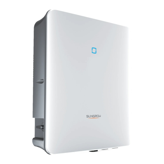
Page 16: Appearance
2 System Solution User Manual 2.1.2 Appearance f f i i g g u u r r e e 2 2 - - 1 1 Appearance * The image shown here is for reference only. The actual product received may differ. D D e e s s c c r r i i p p t t i i o o n n N N o o . -
Page 17: Dc Switch
User Manual 2 System Solution table 2-2 LED indicator description L L E E D D i i n n d d i i c c a a t t o o r r L L E E D D s s t t a a t t e e D D e e f f i i n n i i t t i i o o n n The inverter is running in the on/off-grid mode. - Page 18 I I t t e e m m Compatible with monocrystalline silicon, PV strings polycrystalline silicon, and thin-film without grounding. Inverter SH5.0RT / SH6.0RT / SH8.0RT / SH10RT Three-phase Smart Measures the export power and communicates Energy Meter with the inverter via the RS485 port. Utility grid...
- Page 19 User Manual 2 System Solution If the Smart Energy Meter is abnormal or not equipped, the inverter will run normally, however, the battery can be charged but not allowed to discharge. In this case the feed- in power setting will be ineffective, and the DO function for optimized mode will be disabled.
-
Page 20: Parallel System
2 System Solution User Manual During night, when the battery is empty, it will enter into standby mode. In this case, the grid will supply all power for loads. 2.3 Parallel System Maximum two hybrid inverters with the same type can be connected in parallel in the PV ESS via RS485 communication. - Page 21 User Manual 2 System Solution f f i i g g u u r r e e 2 2 - - 4 4 Parallel PV ESS It is recommended to connect the BACKUP ports of master and slave inverters together to an switchable contactor controlled automatically by the grid voltage.
-
Page 22: Retrofitting The Existing Pv System
2 System Solution User Manual 2.4 Retrofitting the Existing PV System The hybrid inverter is compatible with any three-phase PV grid-connected inverters. An existing PV system can be retrofitted to be a PV ESS with the addition of the hybrid inverter. -
Page 23: Function Description
Function Description 3.1 Safety Function 3.1.1 Protection Several protective functions are integrated in the inverter, including short circuit protection, grounding insulation resistance surveillance, residual current protection, anti- islanding protection, DC overvoltage / over-current protection, etc. 3.1.2 Earth Fault Alarm The inverter has integrated a multiple-function dry-contact (DO relay), which can be used for the external alarm for earth fault. -
Page 24: Drm ("Au"/"Nz")
3 Function Description User Manual power factor (when values out of the rated values) • high altitude • 3.2.2 DRM (“AU”/“NZ”) The inverter provides a terminal block for connecting to a demand response enabling device (DRED). The DRED asserts demand response modes (DRMs). The inverter detects and initiates a response to all supported demand response commands within 2s. -
Page 25: Regular Operational Frequency Range
User Manual 3 Function Description 3.2.4 Regular Operational Frequency Range The inverter can operate within its frequency range for at least the specified observation time. The setting of conditions depends on whether the connection is due to a normal operational start-up or an automatic reconnection after tripping of the interface protection. -
Page 26: Charge Management
3 Function Description User Manual S S t t a a t t e e D D e e f f i i n n i i t t i i o o n n In order to avoid overcharging or deep discharging of the battery, three battery statuses according to different voltage ranges has been defined, as shown in the following table. -
Page 27: Discharge Management
User Manual 3 Function Description table 3-3 Emergency Charge Management for Li-ion Battery S S t t a a t t u u s s C C o o n n d d i i t t i i o o n n s s Either of the following conditions is met: SOC ≤... -
Page 28: Communication And Configuration
3 Function Description User Manual the maximum discharge current of the inverter (30A); • the maximum / recommended discharge current from the battery manufacturer. • For this reason, the battery discharge current value may not reach the nominal power. If the PV voltage is higher than the upper limit value of MPP voltage 1000 V, •... -
Page 29: Unpacking And Storage
Check the inner contents for damage after unpacking. • Contact SUNGROW or the supplier in case of any damage or incompleteness. Do not dispose of the original packing case. It is recommended to store the inverter in it. 4.2 Identifying the Inverter The nameplate can be found on both the inverter and the packing case. - Page 30 I I t t e e m m D D e e s s c c r r i i p p t t i i o o n n SUNGROW logo and product model Technical data of inverter Instructions and marks of conformity...
-
Page 31: Scope Of Delivery
User Manual 4 Unpacking and Storage D D e e s s c c r r i i p p t t i i o o n n I I c c o o n n TÜV mark of conformity CE mark of conformity 4.3 Scope of Delivery f f i i g g u u r r e e 4 4 - - 2 2 Scope of delivery... - Page 32 4 Unpacking and Storage User Manual The storage temperature must be always between -30° C and +70° C, and the • storage relative humidity must be always between 0 and 95 %, non-condensing. In case of stacking storage, the number of stacking layers should never exceed the •...
-
Page 33: Mechanical Mounting
Mechanical Mounting 5.1 Safety during Mounting Make sure there is no electrical connection before installation. In order to avoid electric shock or other injury, make sure that holes will not be drilled over any electricity or plumbing installations. Risk of injury due to improper handling Always follow the instructions when moving and positioning the inverter. -
Page 34: Carrier Requirements
5 Mechanical Mounting User Manual Avoid direct exposure to sun, rain and snow • The inverter should be well ventilated. Ensure air circulation • Never install the inverter in living areas. The inverter will generate noise during • operation, affecting daily life 5.2.2 Carrier Requirements The installation carrier should meet the following requirements: 5.2.3 Installation Angle Requirements... -
Page 35: Installation Tools
User Manual 5 Mechanical Mounting In case of multiple inverters, reserve specific clearance between the inverters. • Install the inverter at an appropriate height for ease of viewing LED indicators and • operating switches. 5.3 Installation Tools Installation tools include but are not limited to the following recommended ones. If necessary, use other auxiliary tools on site. -
Page 36: Moving The Inverter
5 Mechanical Mounting User Manual table 5-1 Tool specification N N o o . . S S p p e e c c i i f f i i c c a a t t i i o o n n Drill bit: D10 Crimp range: 4~6mm Range ≥... -
Page 37: Installing The Inverter
User Manual 5 Mechanical Mounting Lift the inverter using the handles positioned on both sides of the inverter. • Move the inverter by at least two people or by using a proper transport tool. • Do not release the equipment unless it has been firmly secured. •... - Page 38 5 Mechanical Mounting User Manual - - - - E E n n d d...
-
Page 39: Electrical Connection
Electrical Connection 6.1 Safety Instructions Prior to any electrical connections, keep in mind that the inverter has dual power supplies. It is mandatory for the qualified personnel to wear personal protective equipment (PPE) during the electrical work. Danger to life due to a high voltage inside the inverter! The PV string will generate lethal high voltage when exposed to sunlight. - Page 40 6 Electrical Connection User Manual f f i i g g u u r r e e 6 6 - - 1 1 Terminals at the Bottom of the Inverter * The image shown here is for reference only. The actual product received may differ. D D e e s s c c r r i i p p t t i i o o n n N N o o .
-
Page 41: Electrical Connection Overview
User Manual 6 Electrical Connection table 6-2 The label description of COM terminal D D e e s s c c r r i i p p t t i i o o n n N N o o . . L L a a b b e e l l Connect to the Smart Energy Meter. - Page 42 6 Electrical Connection User Manual D D e e s s i i g g n n a a t t i i o o n n I I t t e e m m Router Battery PV string AC circuit breaker Smart Energy Meter Grid Emergency loads...
-
Page 43: Additional Grounding Connection
User Manual 6 Electrical Connection 6.4 Additional Grounding Connection Since the inverter is transformerless , neither the negative pole nor the • positive pole of the PV string must be grounded. Otherwise, the inverter will not operate normally. Connect the additional grounding terminal to the protective grounding point •... -
Page 44: Ac Cable Connection
6 Electrical Connection User Manual 1: Heat shrink tubing 2:OT/DT terminal step 2 Remove the screw on the grounding terminal and fasten the cable with a screwdriver. step 3 Apply paint to the grounding terminal to ensure corrosion resistance. - - - - E E n n d d 6.5 AC Cable Connection 6.5.1 AC Side Requirements A A C C C C i i r r c c u u i i t t B B r r e e a a k k e e r r... -
Page 45: Assembling The Ac Connector
R R e e c c o o m m m m e e n n d d e e d d A A C C c c i i r r c c u u i i t t b b r r e e a a k k e e r r c c u u r r r r e e n n t t SH5.0RT 20 A SH6.0RT... - Page 46 6 Electrical Connection User Manual step 4 Remove the cable jacket by 80~90 mm, and strip the wire insulation by 12 mm. step 5 When using a multi-core multi-strand copper wire cable, connect the AC cable head to the cord end terminal by appropriate torque. Select appropriate cord end terminal according to the cable cross-section •...
-
Page 47: Installing The Ac Connector
User Manual 6 Electrical Connection - - - - E E n n d d 6.5.3 Installing the AC Connector High voltage may be present in inverter! Ensure all cables are voltage-free before electrical connection. Do not connect the AC circuit breaker until all inverter electrical connections are completed. - Page 48 6 Electrical Connection User Manual step 4 ( ( O O p p t t i i o o n n a a l l ) ) Insert the block into AC connector, as shown in the figure below. step 5 Connect PE cable to ground. step 6 Connect phase cable and “N”...
-
Page 49: Dc Cable Connection
• 950 V and 1,000 V. The inverter returns to the running state once the voltage returns to the MPPT operating voltage range, namely, 150 V (only SH5.0RT) / 200 V to 950 V. Make sure the maximum short circuit current on the DC side is within the •... -
Page 50: Dc Side Requirements
SH10RT 6.6.2 DC Side Requirements SUNGROW provides corresponding plug connectors in the scope of delivery for quick connection of PV inputs. DC cables should be connected to the inverter via PV connectors which are included in the scope of delivery. -
Page 51: Assembling The Pv Connector
User Manual 6 Electrical Connection The input current of each input channel should be less than 30 A. 6.6.3 Assembling the PV Connector High voltage may be present in the inverter! Ensure all cables are voltage-free before performing electrical operations. •... -
Page 52: Installing The Pv Connector
6 Electrical Connection User Manual For further assembly and connection instruction, please visit the website of the device manufacturer. step 4 Check for polarity correctness. The inverter will not function properly if any PV polarity is reversed. - - - - E E n n d d 6.6.4 Installing the PV Connector step 1 Rotate the DC switch to “OFF”... -
Page 53: Communication Connection
Arc or contactor over-temperature may occur if the PV connectors are not • firmly in place, and SUNGROW shall not be held liable for any damage caused due to this operation. step 4 Follow the foregoing steps to connect PV connectors of other PV strings. - Page 54 6 Electrical Connection User Manual f f i i g g u u r r e e 6 6 - - 2 2 Ethernet Connection with a Router 6.7.1.1 Assembling the LAN Connector Skip step 1 if the standard network cable with RJ45 plug is prepared. step 1 ( ( O O p p t t i i o o n n a a l l ) ) Strip the insulation layer of the communication cable with an Ethernet wire stripper, and lead the corresponding signal cables out.
- Page 55 User Manual 6 Electrical Connection step 4 Insert the RJ45 plug into the front plug connector until there is an audible click, and install the rubber gasket. - - - - E E n n d d 6.7.1.2 Installing the LAN Connector step 1 Unscrew the waterproof lid from the L L A A N N terminal.
-
Page 56: Wlan Connection
6 Electrical Connection User Manual - - - - E E n n d d 6.7.2 WLAN Connection step 1 Remove the waterproof lid from the W W L L A A N N terminal. step 2 Install the WiFi module. Slightly shake it by hand to determine whether it is installed firmly, as shown below. - Page 57 User Manual 6 Electrical Connection 6.7.3.1 Assembling the COM Connector step 1 Unscrew the swivel nut from the C C O O M M connector. step 2 Take out the terminal block. step 3 Remove the seal and lead the cable through the cable gland. step 4 Remove the cable jacket and strip the wire insulation.
- Page 58 6 Electrical Connection User Manual step 6 Pull the wires outward to check whether they are firmly installed. step 7 Insert the terminal block into the connector until it snaps into place with an audible click. step 8 Fasten the swivel nut. - - - - E E n n d d 6.7.3.2 Installing the COM Connector step 1 Remove the waterproof lid from the C C O O M M terminal.
-
Page 59: Smart Energy Meter Connection
"8.4.1 Feed-in Limitation". Contact SUNGROW to ensure that the Smart Energy Meter model is available locally. This section mainly describes the cable connections on the inverter side. Refer to the quick guide delivered with the Smart Energy Meter for the connections on the meter side. -
Page 60: Connecting The Power Cable
6 Electrical Connection User Manual The plug connector must be connected only by trained electricians. Do not disconnect under load! Battery connectors must not be disconnected while under load. They can be placed in a no load state by shulting down the inverter completely. 6.9.1 Connecting the Power Cable A fuse with the specification of 700 V / 50 A is integrated to the B B A A T T - - terminal. - Page 61 User Manual 6 Electrical Connection step 2 Pry the connection open and pull the sleeve and the insert apart. step 3 Insert the stripped cable into the cable gland up to the stop. The stranded wire can be seen inside the spring. Press the spring down until it audibly snaps into place. step 4 Push the insert into the sleeve and tighten the cable gland (torque 2 N·m).
-
Page 62: Connecting The Can Cable
6 Electrical Connection User Manual 6.9.1.2 Installing the SUNCLIX Connector Only connect these connectors with other SUNCLIX connectors. When making the connections, always observe the specifications regarding nominal voltage and nominal current. The smallest common value is permissible. step 1 Plug the connectors into B B A A T T + + and B B A A T T - - terminals. step 2 Ensure that the connectors are securely in place. - Page 63 User Manual 6 Electrical Connection Consumer load control. In this case the Do relay will control a contactor that will open • or close in certain condintion. Please choose the appropriate contactor according to the load power, e.g. the contactor types of the 3TF30 series from SIEMENS (3TF30 01- 0X).
-
Page 64: Drm/Di Connection ("Au"/"Nz")
6 Electrical Connection User Manual 6.11 DRM/DI Connection (“AU”/“NZ”) The inverter supports the demand response modes as specified in the standard AS/NZS 4777. The inverter has integrated a terminal block for connecting to a DRED. After the connection, the DRED assert DRMs by shorting together terminals as specified "table 6-4 Method of Asserting DRMs". -
Page 65: Assembling The Com Connector
User Manual 6 Electrical Connection The switches that need to be closed in the state of DRM0 ~ DRM8 are shown in the table below. D D e e m m a a n n d d R R e e s s p p o o n n s s e e O O p p e e r r a a t t i i o o n n a a l l I I n n s s t t r r u u c c t t i i o o n n S S w w i i t t c c h h s s t t a a t t e e M M o o d d e e... - Page 66 6 Electrical Connection User Manual step 3 Remove the seal and lead the cable through the cable gland. step 4 Remove the cable jacket by 5 mm–7 mm. step 5 Plug the wires into the corresponding terminal according the labels on the bottom of the inverter.
-
Page 67: Installing The Com Connector
User Manual 6 Electrical Connection step 8 Fasten the swivel nut. - - - - E E n n d d 6.11.2 Installing the COM Connector step 1 Remove the waterproof lid from the C C O O M M terminal. step 2 Insert the COM connector into C C O O M M terminal on the bottom of the inverter until there is an audible click. -
Page 68: Backup Connection
6 Electrical Connection User Manual step 4 Connect the other end to the DRED. - - - - E E n n d d 6.12 Backup Connection P P r r o o c c e e d d u u r r e e step 1 Assembling the BACK-UP Connector. -
Page 69: Commissioning
Commissioning 7.1 Inspection before Commissioning Check the following items before starting the inverter: The inverter DC switch and external circuit breaker are disconnected. • The inverter should be accessible for operation, maintenance and service. • Nothing is left on the top of the inverter. •... -
Page 70: Isolarcloud App
Users can also view inverter information and set parameters through the App. * To achieve direct login via WLAN, the WiFi wireless communication module developed and manufactured by SUNGROW is required. The iSolarCloud App can also establish communication connection to the inverter via wired Ethernet connection. -
Page 71: Login
User Manual 8 iSolarCloud App 8.3 Login 8.3.1 Requirements The following items should meet requirements: The AC and DC sides or the AC side of the inverter is powered-on. • The WLAN function of the mobile phone is enabled. • The mobile phone is within the coverage of the wireless network produced by the of •... - Page 72 8 iSolarCloud App User Manual f f i i g g u u r r e e 8 8 - - 1 1 WLAN Direct step 4 If the inverter is not initialized, navigate to the quick setting screen to initialize protection parameter.
-
Page 73: Initial Settings
User Manual 8 iSolarCloud App 8.4 Initial Settings 8.4.1 Feed-in Limitation The feed-in limitation function requires the using of Smart Energy Meter. Without the Smart Energy Meter, the feed-in limitation function will be unavailable. The function of the feed-in limitation is to control the amount of power injected in the grid by the plant. table 8-1 Description of feed-in limitation parameters D D e e f f a a u u l l t t v v a a l l u u e e R R a a n n g g e e... - Page 74 8 iSolarCloud App User Manual “ “ O O f f f f ” ” M M o o d d e e The reactive power regulation function is disabled. The PF is limited to +1.000. “ “ P P F F ” ” M M o o d d e e The power factor is fixed and reactive power setpoint is calculated according to the current power.
- Page 75 User Manual 8 iSolarCloud App * Curve C is reserved and consistent with Curve A currently. f f i i g g u u r r e e 8 8 - - 2 2 Q(P) Curve “ “ Q Q ( ( U U ) ) ” ” M M o o d d e e The reactive power output of the inverter will vary in response to the grid voltage.
-
Page 76: Function Overview
8 iSolarCloud App User Manual D D e e f f a a u u l l t t E E x x p p l l a a n n a a t t i i o o n n R R a a n n g g e e P P a a r r a a m m e e t t e e r r D D E E... - Page 77 User Manual 8 iSolarCloud App f f i i g g u u r r e e 8 8 - - 5 5 Home table 8-5 Home page description D D e e s s c c r r i i p p t t i i o o n n N N o o .
-
Page 78: Run Information
8 iSolarCloud App User Manual 8.7 Run Information Tap "Run Information" on the navigation bar to enter the corresponding screen, as shown in the following figure. f f i i g g u u r r e e 8 8 - - 6 6 Run Information The run information includes the PV information, inverter information, input, output, grid information, load information, and battery information. -
Page 79: Fault Alarm Record
User Manual 8 iSolarCloud App f f i i g g u u r r e e 8 8 - - 8 8 Power Curve The App displays power generation records in a variety of forms, including daily power generation graph, monthly power generation histogram, annual power generation histogram, and total power generation histogram. -
Page 80: More
8 iSolarCloud App User Manual f f i i g g u u r r e e 8 8 - - 9 9 Fault Alarm Record Click " " to select a time segment and view corresponding records. Select one of the records in the list and click the record, to view the detailed fault info as shown in following figure. -
Page 81: System Parameters
User Manual 8 iSolarCloud App f f i i g g u u r r e e 8 8 - - 1 1 1 1 More The "More" screen supports the following operations: Set parameters including inverter system parameters and energy management •... -
Page 82: Running Time
8 iSolarCloud App User Manual S S y y s s t t e e m m T T i i m m e e The correct system time is very important. Wrong system time will directly affect the data logging and power generation value. The clock is in 24-hour format. 8.9.2 Running Time Tap "Settings ->... -
Page 83: Off-Grid Parameters
User Manual 8 iSolarCloud App 8.9.4 Off-grid Parameters Tap "Settings -> Operation Parameters -> Off-grid Parameters" to enter the screen, as shown in the following figure. f f i i g g u u r r e e 8 8 - - 1 1 5 5 Off-grid Parameters Refer to the description in "8.4.2 Off-grid Mode". -
Page 84: Reactive Power Regulation
8 iSolarCloud App User Manual D D e e s s c c r r i i p p t t i i o o n n R R a a n n g g e e P P a a r r a a m m e e t t e e r r D D e e f f a a u u l l t t Switch for activating/deactivating Active Power... -
Page 85: Battery Forced Charge Time
User Manual 8 iSolarCloud App f f i i g g u u r r e e 8 8 - - 1 1 8 8 Battery Discharge Time 8.9.8 Battery Forced Charge Time Tap "Settings -> Energy Management Parameter-> Battery Forced Charge Time" to enter the corresponding screen. - Page 86 8 iSolarCloud App User Manual f f i i g g u u r r e e 8 8 - - 2 2 0 0 Load Regulation T T i i m m i i n n g g M M o o d d e e In this mode, set the "Load 1 Timing Start Time"...
-
Page 87: Communication Parameters
User Manual 8 iSolarCloud App f f i i g g u u r r e e 8 8 - - 2 2 2 2 DO Operation in Switch Mode I I n n t t e e l l l l i i g g e e n n t t M M o o d d e e The system will control the load operation according to the power optimization algorithm of energy management. -
Page 88: Firmware Update
8 iSolarCloud App User Manual f f i i g g u u r r e e 8 8 - - 2 2 4 4 Communication Parameters The device address ranges from 1 to 246. • The IP adress, gateway, subnet mask, preferred DNS server and alternate DNS •... -
Page 89: Grounding Detection
Unauthorized personnel are not allowed to log in with this account. Otherwise, SUNGROW shall not be held liable for any damages caused. Tap "More -> Settings -> Operation ParameterS -> Grounding Detection" to enter the corresponding screen. -
Page 90: System Decommissioning
System Decommissioning 9.1 Decommissioning the Inverter Please strictly follow the following procedure. Otherwise it will cause lethal voltages or unrecoverable damage to the inverter. 9.1.1 Disconnecting the Inverter For maintenance or other service work, the inverter must be switched off. Proceed as follows to disconnect the inverter from the AC and DC power sources. -
Page 91: Dismantling The Inverter
User Manual 9 System Decommissioning step 9 Insert a MC4 wrench into the notch and press the wrench with an appropriate force to remove the DC connector. step 10Use the multimeter to measure the port voltage of the battery. Disconnect the power cables after the voltage is zero. -
Page 92: Decommissioning The Battery
4 Wait for about 1 minute and then use the multimeter to measure the port voltage of the battery. step 5 If the battery port voltage is zero, disconnect the power cables from the battery module. - - - - E E n n d d SUNGROW is not liable for disposal of the battery. -
Page 93: Troubleshooting And Maintenance
3. Check whether the cross-sectional area of the AC cable meets the requirement. 4. If the alarm persists, contact SUNGROW. Generally, the inverter will be reconnected to the grid after the grid recovers. If the alarm occurs frequently: 1. - Page 94 2. Check, through the App, whether the protection parameters are appropriately set. 3. If the alarm persists, contact SUNGROW. Generally, the inverter will be reconnected to the grid after the grid recovers. If the alarm occurs frequently: 1.
- Page 95 2. If the voltage difference between the three phases is within the permissible range of the local utility grid company, modify the parameter setting through the App. 3. If the alarm persists, contact SUNGROW. PV reverse 1. Check whether the corresponding string is of connection fault reverse polarity.
- Page 96 If the fault persists, check it again when the weather turns fine. 5. If the alarm persists, contact SUNGROW. 1. Check whether the AC cable is correctly connected.
- Page 97 2. Check whether the Smart Energy Meter is connection connected to a wrong terminal, instead of the grid- connected point. If so, correct it. 3. If the alarm persists, contact SUNGROW. 1. Check whether the Smart Energy Meter communication cable and terminal are abnormal. If Smart Energy so, remove the corresponding abnormity.
-
Page 98: Maintenance
System alarm ambient environment is abnormal. If so, take corrective measures. 2. If the alarm persists, contact SUNGROW. 1. Wait for the inverter to recover. 2. Disconnect the AC and DC switches or circuit System fault breakers, and connect them again after 15 minutes. -
Page 99: Replacing The Button Cell
Lethal voltage still exists in the inverter. Please wait at least 10 minutes and then perform maintenance work. There is a button cell on the inner PCB board. Contact SUNGROW for replacement when the relevant fault alarm occurs. Check the fastener, appearance, voltage, and resistance quarterly and annually. -
Page 100: Appendix
11 Appendix 11.1 Technical Data P P a a r r a a m m e e t t e e r r s s S S H H 5 5 . . 0 0 R R T T S S H H 6 6 . . 0 0 R R T T P P V V I I n n p p u u t t Max. - Page 101 User Manual 11 Appendix P P a a r r a a m m e e t t e e r r s s S S H H 5 5 . . 0 0 R R T T S S H H 6 6 . . 0 0 R R T T 3 / N / PE, 220 / 380 V;...
- Page 102 11 Appendix User Manual P P a a r r a a m m e e t t e e r r s s S S H H 5 5 . . 0 0 R R T T S S H H 6 6 . . 0 0 R R T T M M e e c c h h a a n n i i c c a a l l D D a a t t a a Dimensions (W x H x D) 460 mm x 540 mm x 170 mm...
- Page 103 User Manual 11 Appendix P P a a r r a a m m e e t t e e r r s s S S H H 8 8 . . 0 0 R R T T S S H H 1 1 0 0 R R T T Battery voltage 150 V...600 V Max.
-
Page 104: Quality Assurance
* Depending on the connected battery 11.2 Quality Assurance When product faults occur during the warranty period, SUNGROW will provide free service or replace the product with a new one. E E v v i i d d e e n n c c e e During the warranty period, the customer shall provide the product purchase invoice and date. -
Page 105: Contact Information
E E x x c c l l u u s s i i o o n n o o f f L L i i a a b b i i l l i i t t y y In the following circumstances, SUNGROW has the right to refuse to honor the quality guarantee: The free warranty period for the whole machine/components has expired. - Page 106 C C h h i i n n a a ( ( H H Q Q ) ) A A u u s s t t r r a a l l i i a a Sungrow Australia Group Pty. Ltd. Sungrow Power Supply Co., Ltd...
- Page 107 R R o o m m a a n n i i a a T T u u r r k k e e y y Service Partner - Elerex Sungrow Deutschland GmbH Turkey Istanbul Representative Bureau +40 241762250 Istanbul service.romania@sungrow.co...
Need help?
Do you have a question about the SH5.0RT and is the answer not in the manual?
Questions and answers