Sungrow SH5 0RT Series User Manual

Sungrow SH5 0RT Series User Manual

3-phase hybrid inverter
Table of Contents

Advertisement

User Manual
3–Phase Hybrid Inverter
SH5.0RT/SH6.0RT/SH8.0RT/SH10RT
SH5.0RT/
6.0_8.0_10RT-UEN-Ver19-202210
SH5.0_6.0_8.0_10RT-UEN-Ver19-202210

Advertisement

Table of Contents
loading

Summary of Contents for Sungrow SH5 0RT Series

  • Page 1 User Manual 3–Phase Hybrid Inverter SH5.0RT/SH6.0RT/SH8.0RT/SH10RT SH5.0RT/ SH6.0RT/SH8.0RT/SH10RT3–Phase Hybrid Inverter User ManualSH5.0_ 6.0_8.0_10RT-UEN-Ver19-202210 SH5.0_6.0_8.0_10RT-UEN-Ver19-202210...
  • Page 3: All Rights Reserved

    Software Licenses • It is prohibited to use data contained in firmware or software developed by SUNGROW, in part or in full, for commercial purposes by any means. • It is prohibited to perform reverse engineering, cracking, or any other operations that...
  • Page 4: About This Manual

    Please read this manual carefully before using the product and keep it properly at a place for easy access. All contents, pictures, marks, and symbols in this manual are owned by SUNGROW. No part of this document may be reprinted by the non-internal staff of SUNGROW without written authorization.
  • Page 5 Symbols This manual contains important safety instructions, which are highlighted with the following symbols, to ensure personal and property safety during usage, or to help optimize the prod- uct performance in an efficient way. Please carefully understand the meaning of these warning symbols to better use the manual. Indicates high-risk potential hazards that, if not avoided, may lead to death or seri- ous injury.
  • Page 7: Table Of Contents

    Contents All Rights Reserved .....................I About This Manual......................II 1 Safety Instructions ....................1 1.1 Unpacking and Inspection ................1 1.2 Installation Safety ...................2 1.3 Electrical Connection Safety................2 1.4 Operation Safety ....................4 1.5 Maintenance Safety ..................4 1.6 Disposal Safety ....................5 2 Product Description ..................6 2.1 System Introduction ..................6 2.2 
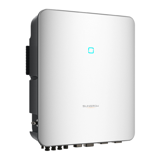
Product Introduction..................6...
  • Page 8 3.2.2 DRM (“AU”/“NZ”).................23 3.2.3 Regular Operational Voltage Range .............23 3.2.4 Regular Operational Frequency Range ..........24 3.2.5 Reactive Power Regulation..............24 3.2.6 Load Control..................24 3.3 Battery Management ..................24 3.3.1 Charge Management................26 3.3.2 Discharge Management...............27 3.4 Communication and Configuration ..............28 4 Unpacking and Storage .................29 4.1 Unpacking and Inspection ................29 4.2 Scope of Delivery ..................30...
  • Page 9 6.6.2 Assembling the PV Connectors ............55 6.6.3 Installing the PV Connector..............56 6.7 Communication Connection ................57 6.7.1 Ethernet Connection................57 6.7.2 WiNet-S Connection................59 6.7.3 RS485 Connection ................62 6.8 Smart Energy Meter Connection ..............65 6.9 Battery Connection ..................65 6.9.1 Connecting the Power Cable..............66 6.9.2 Connecting the CAN Cable ..............69 6.9.3 Connecting the Enable Cable...............69 6.10 EV-Charger Communication Connection ............70...
  • Page 10 8.9.1 Chart....................98 8.9.2 Fault Alarm Record ................99 8.9.3 Event Records .................. 100 8.10 Inverter (Optional)..................101 8.11 EV-Charger (Optional)................102 8.11.1 Driving Distance Per kWh..............104 8.11.2 Charging Mode................104 8.11.3 Parameter Setting ................109 8.11.4 Start/Stop Switch................110 8.12 More ......................111 8.12.1 System Parameters.................
  • Page 11 10.2.1 Maintenance Notices ............... 132 10.2.2 Routine Maintenance............... 133 10.2.3 Replacing the Button Cell..............133 11 Appendix ...................... 134 11.1 Technical Data ..................134 11.2 The Compatibility for Backup under Off-grid Scenario ........139 11.3 Quality Assurance..................140 11.4 Contact Information................... 141...
  • Page 13: Safety Instructions

    Perform operations considering ac- tual onsite conditions. • SUNGROW shall not be held liable for any damage caused by violation of gen- eral safety operation requirements, general safety standards, or any safety in- struction in this manual.
  • Page 14: Installation Safety

    1 Safety Instructions User Manual Installation Safety Make sure there is no electrical connection before installation. Before drilling, avoid the water and electricity wiring in the wall. Improper installation may cause personal injury! • If the product supports hoisting transport and is hoisted by hoisting tools, no one is allowed to stay under the product.
  • Page 15 User Manual 1 Safety Instructions Danger to life due to a high voltage inside the inverter! • Be sure to use special insulation tools during cable connections. • Note and observe the warning labels on the product, and perform operations strictly following the safety instructions.
  • Page 16: Operation Safety

    1 Safety Instructions User Manual Operation Safety Please comply with the following requirements when the product is running: • Do not touch its enclosure. • It is strictly forbidden to plug and unplug any connector on the inverter. • Do not touch any wiring terminal of the inverter. Otherwise, electric shock may occur.
  • Page 17: Disposal Safety

    To avoid the risk of electric shock, do not perform any other maintenance opera- tions beyond those described in this manual. If necessary, contact your distributor first. If the problem persists, contact SUNGROW. Otherwise, the losses caused is not covered by the warranty.
  • Page 18: Product Description

    Product Description System Introduction • The inverter must only be operated with PV strings with class II protection in ac- cordance with IEC 61730, application class A. It is not allowed for the positive pole or the negative pole of the PV strings to be grounded. This can cause the inverter to be destroyed.
  • Page 19 User Manual 2 Product Description figure 2-1 Inverter Appearance Description Name LED indicator panel Indicates the current working state of the inverter. DC switch(Optional) Used to safely disconnect the DC circuit. Includes DC terminals, AC terminals, battery terminals, Electrical connection communication terminals and additional grounding area terminal.
  • Page 20: Symbols On The Product

    2 Product Description User Manual figure 2-2 Dimensions of the Inverter Weight(kg) W(mm) H(mm) D(mm) Symbols on the Product Symbol Explanation RCM mark of conformity. TÜV mark of conformity. CE mark of conformity. EU/EEA Importer Do not dispose of the inverter together with household waste. The inverter does not have a transformer.
  • Page 21: Led Indicator

    User Manual 2 Product Description Symbol Explanation Danger to life due to high voltages! Only qualified personnel can open and service the inverter. Do not touch live parts for 10 minutes after disconnection from the power sources. Additional grounding point. LED Indicator The LED indicator on the front of the inverter indicates the working state of the inverter.
  • Page 22: Pv Energy Storage System (Pv Ess)

    2 Product Description User Manual The inverter operates automatically when input and output requirements are met. Rotate the DC switch to the “OFF” position to stop the inverter when a fault occurs or when you need to stop the inverter. Turn the DC switch to the “ON”...
  • Page 23: Declaration For Back-Up Function

    PV modules and batteries. If there is no available power from batteries or PV modules in backup mode, the backup power supply will be automatically terminated. SUNGROW shall hold no liability for any consequences arising from failing to observe this instruction.
  • Page 24 2 Product Description User Manual When the grid is present, the bypass function of the hybrid inverter is activated and the Backup loads will be directly connected to the grid via the bypass switch integrated in the inverter. If the Smart Energy Meter is abnormal or not equipped, the inverter will run normally, how- ever, the battery can be charged but not allowed to discharge.
  • Page 25: Parallel System

    User Manual 2 Product Description With current No current During night, when the battery is empty, it will enter into standby mode. In this case, the grid will supply all power for loads. With current No current Parallel System 2.7.1 Grid-connected Parallel System Maximum five hybrid inverters with the same type can be connected in parallel in the PV ESS via RS485 communication.
  • Page 26 2 Product Description User Manual figure 2-4 Parallel PV ESS (A) Master (B) Slave 1 (C) Slave 2 (D) GRID (E) BACK-UP (F) RS485 Only the inverter GRID terminal can be connected in parallel, the BACK-UP termi- nal and the battery terminal cannot be connected together, they should be con- nected to the backup loads, which need uninterrupted power supply, and the battery respectively.
  • Page 27: Off-Grid Parallel System

    • This section is not applicable for Europe but only for other regions. Please con- tact SUNGROW for details of specific regions and models. In off-grid parallel mode, devices are controlled by the smart switch at the grid-connected point, and relevant parameters can be set on iSolarCloud App.
  • Page 28 2 Product Description User Manual Only 2~5 inverters can be connected in parallel. If inverters of the same power are con- nected in parallel, the output power is the sum of the power of each inverter. If inverters of different power are connected in parallel, the output power is the product of the minimum power value of a single inverter and the number of inverters.
  • Page 29 User Manual 2 Product Description figure 2-7 Wiring diagram for other regions * * Ensure that only the PE cable at the backup port of the master inverter is grounded in re- gions beyond Australia and New Zealand. If there is more than one inverter in the system, the backup terminal of inverters cannot be connected to loads, nor can they be connected in parallel.
  • Page 30: Pv Storage And Ev-Charging System

    2 Product Description User Manual • Off-grid mode enabling. Refer to "8.12.5 O_Off-grid_Parameters.dita". The off-grid mode is off by default and can be enabled first when inverters are turned on. • Parallel configuration. Refer to "8.12.14 Parallel Configuration" to configure the master and slave inverters on iSolarCloud App.If there is only one inverter in the system, disable the parallel configuration function.
  • Page 31: Retrofitting The Existing Pv System

    User Manual 2 Product Description figure 2-8 PV Storage and EV-Charger System table 2-3 System Compositions Description Remark Item Compatible with monocrystalline silicon, PV strings polycrystalline silicon, and thin-film without grounding. Inverter SH5.0RT / SH6.0RT / SH8.0RT / SH10RT Three-phase Smart Measures the export power and communicates Energy Meter with the inverter via the RS485 port.
  • Page 32 2 Product Description User Manual On-grid Port to Retrofit the Existing PV System figure 2-9 On-grid Port to Retrofit the Existing PV System The AC terminal of the PV inverter and the GRID terminal of the hybrid inverter are con- nected in parallel.
  • Page 33: Retrofitted Pv Storage And Ev-Charging System

    User Manual 2 Product Description Note: In zero-export scenario, the hybrid inverter can only ensure no power exported to grid it- self but does not ensure zero export for the PV inverter. Please contact the PV inverter manufacturer for its zero-export solution. PV modules for hybrid inverter are optional.
  • Page 34: Function Description

    Function Description Safety Function 3.1.1 Protection Several protective functions are integrated in the inverter, including short circuit protection, grounding insulation resistance surveillance, residual current protection, anti-islanding pro- tection, DC overvoltage / over-current protection, etc. 3.1.2 Earth Fault Alarm The inverter has integrated a multiple-function dry-contact (DO relay), which can be used for the external alarm for earth fault.
  • Page 35: Drm ("Au"/"Nz")

    User Manual 3 Function Description • power factor (when values out of the rated values) • high altitude 3.2.2 DRM (“AU”/“NZ”) The inverter provides a terminal block for connecting to a demand response enabling device (DRED). The DRED asserts demand response modes (DRMs). The inverter detects and ini- tiates a response to all supported demand response commands within 2s.
  • Page 36: Regular Operational Frequency Range

    Battery Management Li-ion battery from SUNGROW, LG Chem, BYD and Pylontech are compatible with the PV ESS,further battery models will be made compatible in the furture. The currently supported battery brands and models are shown in the following table.
  • Page 37 The table is continually updated. If the battery model is not in the table, consult SUNGROW if it is supported. To maximize the battery life, the inverter will perform battery charge, discharge, and battery maintenance based on the battery status communicated by the BMS.
  • Page 38: Charge Management

    3 Function Description User Manual Port Voltage / SOC Type Empty Normal Full BYD (Battery-Box 5 %...100 %) Premium HVM / SOC < 5 % SOC = 100 % (by default) HVS) Pylontech (Power- cube-X1/X2/H1/H2) 8 %...100 % SOC < 8 % SOC = 100 % Pylontech (Force (by default)
  • Page 39: Discharge Management

    The emergency charge command reported to the inverter is cleared. table 3-4 Default SOC Conditions for Li-ion Battery Backup Charge Type Trigger SOC Finishing SOC SUNGROW SOC ≤ 2 % SOC ≥ 4 % LG Chem SOC ≤ 5 % SOC ≥...
  • Page 40: Communication And Configuration

    3 Function Description User Manual • the maximum discharge current of the inverter (30A); • the maximum / recommended discharge current from the battery manufacturer. For this reason, the battery discharge power may not reach the nominal power. • If the PV voltage is higher than 900 V, the battery cannot discharge. •...
  • Page 41: Unpacking And Storage

    • Check the inner contents for damage after unpacking. Contact SUNGROW or the transport company in case of any damage or incompleteness, and provide photos to facilitate services. Do not dispose of the original packing case. It is recommended to store the device in the original packing case when the product is decommissioned.
  • Page 42: Scope Of Delivery

    4 Unpacking and Storage User Manual Scope of Delivery figure 4-1 Scope of delivery Item Name Quantity Inverter Wall-mounting bracket * Expansion plug set M4 screws and washers AC/Backup connector set Block (Optional) Cord end terminal * PV connectors 2 ~ 3 Crimp contact 2 ~ 3 SUNCLIX connector set...
  • Page 43: Inverter Storage

    User Manual 4 Unpacking and Storage Inverter Storage Proper storage is required if the inverter is not installed immediately. • Store the inverter in the original packing case with the desiccant inside. • The storage temperature must be always between -30℃ and +70℃, and the storage rel- ative humidity must be always between 0 and 95 %, non-condensing.
  • Page 44: Mechanical Mounting

    Mechanical Mounting Respect all local standards and requirements during mechanical installation. Safety during Mounting Make sure there is no electrical connection before installation. Before drilling, avoid the water and electricity wiring in the wall. Poor installation environment will affect system performance! •...
  • Page 45: Environment Requirements

    User Manual 5 Mechanical Mounting 5.2.1 Environment Requirements • The installation environment must be free of inflammable or explosive materials. • The location should be not accessible to children. • The ambient temperature and relative humidity must meet the following requirements. •...
  • Page 46: Angle Requirements

    5 Mechanical Mounting User Manual 5.2.3 Angle Requirements Install the inverter vertically. Never install the inverter horizontally, or at forward/backward tilted, or upside down. 5.2.4 Clearance Requirements Reserve enough clearance around the inverter to ensure sufficient space for heat dissipation. In case of multiple inverters, reserve specific clearance between the inverters.
  • Page 47 User Manual 5 Mechanical Mounting Goggles Earplugs Dust mask Protective gloves Insulated shoes Utility knife Slotted screwdriver Phillips screwdriver (M4) (M4) Hammer drill Marker Vacuum cleaner Rubber mallet (φ10) Wrist strap Wire cutter Wire stripper Hydraulic plier Heat gun MC4 terminal MC4 terminal Multimeter crimping pliers...
  • Page 48: Moving The Inverter

    5 Mechanical Mounting User Manual Wrench RJ45 crimping tool (16 mm, 46 mm) Moving the Inverter Before installation, remove the inverter from the packing case and move it to the installation site. Follow the instructions below as you move the inverter: •...
  • Page 49 User Manual 5 Mechanical Mounting (1) Self-tapping (2) Expansion tube (3) Fender washer (4) Spring washer screw step 1 Install the wall-mounting bracket. Note: The depth of the holes should be about 70 mm. The bubble in the bubble level on the mounting-bracket must be centered to ensure that the device will be placed horizontally.
  • Page 50 5 Mechanical Mounting User Manual - - End...
  • Page 51: Electrical Connection

    Electrical Connection Safety Instructions The PV string will generate lethal high voltage when exposed to sunlight. • Operators must wear proper personal protective equipment during electrical connections. • Must ensure that cables are voltage-free with a measuring instrument before touching DC cables. •...
  • Page 52: Terminal Description

    6 Electrical Connection User Manual All electrical connections must comply with local and national / regional electrical standards. • Cables used by the user shall comply with the requirements of local laws and regulations. • Only with the permission of the national / regional grid department, the inverter can be connected to the grid.
  • Page 53 User Manual 6 Electrical Connection Description Name Positive and negative DC input connectors PV terminals Two or three pairs, depending on the inverter model Battery connection Connectors for the battery power cables WLAN terminal Connector for the WiNet—S module Connector for the EMS, router, and data logger LAN terminal Additional grounding For reliable grounding...
  • Page 54: Electrical Connection Overview

    6 Electrical Connection User Manual Description Label To enable the communication between the inverter and BMS/CAN the Li-ion battery Connect to the LG Chem Li-ion battery,use with Enable RS485 terminal • "AU"/"NZ": Demand response enabling device (DRED) DI/DRM • "IT": interface protection system (SPI) •...
  • Page 55 User Manual 6 Electrical Connection table 6-3 Cable requirements Specification Type Outer Cable Cross section diameter CAT 5E outdoor shielded Ethernet cable 5.3 ~ 7 mm 8 * 0.2 mm² network cable Complying with 1,000V 4 mm² and 35A standard Power Cable 5.5 ~ 8 mm Complying with 1,000V...
  • Page 56 6 Electrical Connection User Manual SH5.0/6.0RT SH8.0/10RT ① 40A/600V DC breaker * ② 32A/400V AC breaker ③ 25A/400V AC breaker ④ Depends on loads ⑤ Depends on household loads and inverter capacity ⑥⑦ 30mA RCD (Comply with local regulation) Note: * If the battery is integrated with a readily accessible internal DC breaker, no additional DC breaker is required.
  • Page 57: External Protective Grounding Connection

    User Manual 6 Electrical Connection In the TT system, the following diagram is an example for grid systems without special re- quirement on wiring connection. SH5.0/6.0RT SH8.0/10RT ① 40A/600V DC breaker * ② 32A/400V AC breaker ③ 25A/400V AC breaker ④...
  • Page 58: External Protective Grounding Requirements

    AC side grounding terminal are reliably grounded. The grounding connection can be made by other means if they are in accordance with the local standards and regulations, and SUNGROW shall not be held liable for the possible consequences.
  • Page 59: Ac Cable Connection

    User Manual 6 Electrical Connection (1) Heat shrink tubing (2) OT/DT terminal step 2 Remove the screw on the grounding terminal and fasten the cable with a screwdriver. step 3 Apply paint to the grounding terminal to ensure corrosion resistance. - - End AC Cable Connection 6.5.1 AC Side Requirements...
  • Page 60: Assembling The Ac Connector

    6 Electrical Connection User Manual Before connecting the inverter to the grid, ensure the grid voltage and frequency comply with requirements, for which, refer to "Technical Date". Otherwise, contact the electric power company for help. AC Circuit Breaker An independent three or four-pole circuit breaker must be installed on the output side of the inverter to ensure safe disconnection from the grid.
  • Page 61 User Manual 6 Electrical Connection step 2 (Optional) Remove the inner sealing ring if the cable diameter is between 19 mm ~ 25 mm. Otherwise skip this step. step 3 Take out the terminal plug from the housing. step 4 Thread the AC cable of appropriate length through the swivel nut and the housing. step 5 Strip 80 mm ~ 90 mm of the cable jacked and 12 mm of the wire insulation.
  • Page 62 6 Electrical Connection User Manual step 6 (Optional) When using a multi-core multi-strand copper wire cable, connect the AC wire head to the cord end terminal (hand-tight). In case of single-strand copper wire, skip this step. Select appropriate cord end terminal according to the cable cross-section area. step 7 Fix all the wires to the terminal plug according to the assignment and tighten to a torque of 1.2 N•m–1.5 N•m with a screwdriver.
  • Page 63: Installing The Ac Connector

    User Manual 6 Electrical Connection 6.5.3 Installing the AC Connector High voltage may be present in inverter! Ensure all cables are voltage-free before electrical connection. Do not connect the AC circuit breaker until all inverter electrical connections are completed. step 1 Disconnect the AC circuit breaker and secure it against reconnection. step 2 Remove the waterproof lid from the GRID terminal.
  • Page 64: Dc Cable Connection

    6 Electrical Connection User Manual Insert block ① into AC connector ② from the side. Tighten the screw on the bottom of block ①. step 5 Connect PE cable to ground. step 6 Connect phase cable and “N” cable to AC circuit breaker. step 7 Connect AC circuit breaker to utility grid.
  • Page 65: Pv Input Configuration

    The damage caused by this is not covered by the warranty. • Electric arc or contactor over-temperature may occur if the PV connectors are not firmly in place, and SUNGROW shall not be held liable for any damage caused. •...
  • Page 66 6 Electrical Connection User Manual For SH5.0/6.0/8.0RT, each PV input operates independently and has its own MPPT. In this way, string structures of each PV input may differ from each other, including PV module type, number of PV modules in each string, angle of tilt, and installation orientation. For SH10RT, each pair of PV terminals is corresponding to an independent PV string.
  • Page 67: Assembling The Pv Connectors

    User Manual 6 Electrical Connection 6.6.2 Assembling the PV Connectors High voltage may be present in the inverter! • Ensure all cables are voltage-free before performing electrical operations. • Do not connect the DC switch and AC circuit breaker before finishing electrical connection.
  • Page 68: Installing The Pv Connector

    6 Electrical Connection User Manual step 4 Check for polarity correctness. If the PV polarity is reversed, the inverter will be in a fault or alarm state and will not operate normally. - - End 6.6.3 Installing the PV Connector step 1 Rotate the DC switch to “OFF”...
  • Page 69: Communication Connection

    User Manual 6 Electrical Connection If the PV string is equipped with the optimizer, please refer to the optimizer manual for elec- trical connections and make sure that the polarity of the optimizer cables is correct. - - End Communication Connection LAN function •...
  • Page 70 6 Electrical Connection User Manual step 4 Insert the RJ45 plug into the front plug connector until there is an audible click, and install the rubber gasket. - - End 6.7.1.2 Installing the LAN Connector step 1 Unscrew the waterproof lid from the LAN terminal. step 2 Insert the LAN connector into LAN terminal on the bottom of the inverter.
  • Page 71: Winet-S Connection

    User Manual 6 Electrical Connection - - End 6.7.2 WiNet-S Connection The WiNet-S module supports Ethernet communication and WLAN communication. It is not recommended to use both communication methods at the same time. (A) Inverter (B) Router/Switch (C) iSolarCloud server (D) iSolarCloud App (E) iSolarCloud Internet...
  • Page 72 6 Electrical Connection User Manual 6.7.2.1 Ethernet Communication step 1 (Optional) Strip the insulation layer of the communication cable with an Ethernet wire strip- per, and lead the corresponding signal cables out. Insert the stripped communication cable into the RJ45 plug in the correct order, and crimp it with a crimper. 1: RJ45 plug 2: Protective cap Skip this step if a standard network cable with RJ45 plug is prepared.
  • Page 73 User Manual 6 Electrical Connection step 5 Insert the RJ45 plug into the front plug connector until there is an audible click and tighten the housing. Install the gasket and fasten the swivel nut. step 6 Remove the waterproof lid from the WLANterminal and install WiNet-S. step 7 Slightly shake it by hand to determine whether it is installed firmly.
  • Page 74: Rs485 Connection

    6 Electrical Connection User Manual step 3 Refer to the guide delivered with the module for the set-up. - - End 6.7.3 RS485 Connection Where there is only one inverter, the RS485 can be connected to an external device for the communication.
  • Page 75 User Manual 6 Electrical Connection step 3 Remove the seal and lead the cable through the cable gland. step 4 Remove the cable jacket and strip the wire insulation. step 5 Plug the wires into the RS485 terminal according the labels on the bottom of the inverter. step 6 Pull the wires outward to check whether they are firmly installed.
  • Page 76 6 Electrical Connection User Manual step 8 Fasten the swivel nut. - - End 6.7.3.2 Installing the COM Connector step 1 Remove the waterproof lid from the COM terminal. step 2 Insert the COM connector into COM terminal on the bottom of the inverter until there is an audible click.
  • Page 77: Smart Energy Meter Connection

    For the setting of feed-in power limit, refer to the section "8.5.1 Feed-in Limitation". Contact SUNGROW to ensure that the Smart Energy Meter model is available locally. This section mainly describes the cable connections on the inverter side. Refer to the quick guide delivered with the Smart Energy Meter for the connections on the meter side.
  • Page 78: Connecting The Power Cable

    6 Electrical Connection User Manual During the installation and operation of the inverter, please ensure that the positive or negative polarities of batteries do not short-circuit to the ground. Otherwise, an AC or DC short-circuit may occur, resulting in equipment damage. The damage caused by this is not covered by the warranty.
  • Page 79 User Manual 6 Electrical Connection step 2 Pry the connection open and pull the sleeve and the insert apart. step 3 Insert the stripped cable into the cable gland up to the stop. The stranded wire can be seen inside the spring. Press the spring down until it audibly snaps into place. step 4 Push the insert into the sleeve and tighten the cable gland (torque 2 N·m).
  • Page 80 6 Electrical Connection User Manual step 1 Plug the connectors into BAT+ and BAT- terminals. step 2 Ensure that the connectors are securely in place. - - End 6.9.1.3 Assembling Evo2 Compatible Connector The connector type is subject to the actual received device. step 1 Strip 15 mm of the insulation layer from each PV cable.
  • Page 81: Connecting The Can Cable

    - - End 6.9.2 Connecting the CAN Cable The CAN cable enables the communication between the inverter and the Li-ion battery from SUNGROW, BYD and Pylontech. Procedure For detailed connection description of the CAN cable, refer to the section "6.7.3 RS485 Con- nection".
  • Page 82: Ev-Charger Communication Connection

    6 Electrical Connection User Manual For detailed connection description of the Enable cable, refer to the section "6.7.3 RS485 Connection". Plug the wires into the Enable terminal according the labels on the bottom of the inverter. 6.10 EV-Charger Communication Connection The inverter communicates with the charger through the RS485 communication interface.
  • Page 83: Di Connection

    User Manual 6 Electrical Connection Relay Trigger condition Description The load control mode The relay is activated once the conditions Consumer load has been set via the iSo- of the control mode are satisfied. See control larCloud App. "8.12.10 Load Control".
  • Page 84 6 Electrical Connection User Manual table 6-4 Method of Asserting DRMs Asserted by Shorting Terminals Mode DRM0 R & C DRM1 D1/5 & C DRM2 D2/6 & C DRM3 D3/7 & C DRM4 D4/8 & C DRM5 D1/5 & R DRM6 D2/6 &...
  • Page 85: Assembling The Com Connector

    User Manual 6 Electrical Connection 6.12.1 Assembling the COM Connector step 1 Unscrew the swivel nut from the connector. step 2 Take out the terminal block. step 3 Remove the seal and lead the cable through the cable gland. step 4 Remove the cable jacket by 7 mm–10 mm.
  • Page 86: Installing The Com Connector

    6 Electrical Connection User Manual step 5 Plug the wires into the corresponding terminal according the labels on the bottom of the inverter. step 6 Pull the wires outward to check whether they are firmly installed. step 7 Insert the terminal block into the connector until it snaps into place with an audible click. step 8 Fasten the swivel nut.
  • Page 87: Backup Connection

    User Manual 6 Electrical Connection step 2 Insert the COM connector into COM terminal on the bottom of the inverter until there is an audible click. step 3 Pull cables outwards to confirm whether they are fastened firmly. step 4 Connect the other end to the DRED / Ripple Control Receiver device. - - End 6.13 Backup Connection step 1 Assembling the BACK-UP Connector.
  • Page 88 6 Electrical Connection User Manual step 3 Align the Backup connector and the BACK-UP terminal and mate them together by hand un- til a “Click” is heard or felt. step 4 Pull all the lines outward to check whether they are firmly installed. - - End...
  • Page 89: Commissioning

    Commissioning Inspection before Commissioning Check the following items before starting the inverter: • All equipment has been reliably installed. • DC switch(es) and AC circuit breaker are in the "OFF" position. • The ground cable is properly and reliably connected. •...
  • Page 90: App Preparation

    "8.3 Account Registration". If you have got the account and password from the distributor/installer or SUNGROW, skip this step. step 3 Download the firmware package to the mobile device in advance. Refer to “Firmware Upa- date”. This is to avoid download failure due to poor on-site network signal.
  • Page 91 User Manual 7 Commissioning step 4 Fill in the content according to actual needs, and the parameters containing * are required. Tap Next to enter the next interface. figure 7-2 Plant Creation Settings Parameter Description Name Plant name The name of the plant. Plant type The type of the plant, which should be set corresponding to the actual plant type.
  • Page 92 7 Commissioning User Manual Parameter Description Name Time zone The time zone where the plant is located, which can be filled through automatic positioning and manual input. The location of the plant, which can be filled in two ways: • Manually: Manually enter the plant location in the input box.
  • Page 93 User Manual 7 Commissioning step 6 After a device is bound, tap Device and Commissioning to go to corresponding interface. step 7 Tap Network Configuration to go to the WLAN connection interface. Tap the home net- work in the WLAN list, enter the password, and then tap Confirm.
  • Page 94 7 Commissioning User Manual step 8 Enter the Activate EasyConnect interface, and press the multi-function button on the WiNet-S to enable the Easyconnect mode according to the prompt on the screen. The App automatically enters a waiting processing interface if this mode is enabled, and automatically returns to the commissioning interface after the processing is completed.
  • Page 95 User Manual 7 Commissioning When the country is set to Australia, additionally set the applicable network service provider and then the grid type. The image shown here is for reference only. Refer to the actual interface for the supported network service providers.
  • Page 96 7 Commissioning User Manual table 7-1 Description of Network Service Provider and Grid Type Network Service Provider Grid Type AS/NZS 4777.2:2015 AS/NZS 4777.2:2020 Australia A AS/NZS 4777.2:2020 Australia B AS/NZS 4777.2:2020 Australia C • STNW1170: single-phase < 10 kVA & ENERGEX &...
  • Page 97 User Manual 7 Commissioning • Please check the country supported by this product at http:// support.sungrow- power.com/. • Set Country/Region to the country/region where the inverter is installed. Oth- erwise, the inverter may report a fault. step 10 After a plant is successfully created, return to the App home page to view the plant information.
  • Page 98: Isolarcloud App

    App. * To achieve direct login via WLAN, the wireless communication module developed and manufactured by SUNGROW is required. The iSolarCloud App can also establish communi- cation connection to the inverter via Ethernet connection.
  • Page 99: Account Registration

    User Manual 8 iSolarCloud App Account Registration The account distinguishes two user groups, end user and distributor/installer. • The end user can view plant information, create plants, set parameters, share plants, etc. • The distributor/installer can help the end user to create plants, manage, install, or main- tain plants, and manage users and organizations.
  • Page 100: Login

    8 iSolarCloud App User Manual step 4 Fill in the registration information, including email, verification code, password and affirm- ance and country (region). The distributor/installer has the permission to fill in the company name and the code of upper level installer/distributor. The code of upper level distributor/installer can be obtained from the upper level distributor/installer.
  • Page 101 User Manual 8 iSolarCloud App figure 8-1 Enabling the WLAN Hotspot step 2 Connect the mobile phone to the WLAN network named as "SG-xxxxxxxxxxx" (xxxxxxxxxxx is the serial number indicated on the side of the communication module). step 3 Open the App to enter the login screen. Tap Local Access to enter the next screen. step 4 Tap Confirm, then enter the password and tap LOGIN.Or tap MANUAL CONNECTION at the bottom of the interface and select WiNet-S, then enter the password and tap LOGIN.
  • Page 102: Initial Settings

    8 iSolarCloud App User Manual figure 8-3 WLAN Local Access step 6 After finishing the settings, tap TUNR ON DEVICE at the upper right corner and the device will be initialized. The App will send start instructions and the device will start and operate. step 7 After initialization settings, the App will return automatically to the home page.
  • Page 103: Backup Mode

    User Manual 8 iSolarCloud App Range Default value Parameter Germany Germany Others Others Feed-in Limita- 70.0% 100.0% 0 ~ 100% tion Ratio Rated Power of Original Power Depends on inverter power of other companies Generation Systems *If power control is regulated by a third party logger, please enable the power limitation to 100% in default.
  • Page 104 8 iSolarCloud App User Manual “Q(P)” Mode The PF of the inverter output varies in response to the output power of the inverter. table 8-3 “Q(P)” Mode Parameter Descriptions: Default Explanation Range Parameter Select corresponding curve ac- Q(P) Curve A, B, C cording to local regulations Output power at P1 on the Q(P) QP_P1...
  • Page 105 User Manual 8 iSolarCloud App table 8-4 “Q(U)” Mode Parameter Descriptions: Default Explanation Range Parameter Select corresponding curve ac- Q(U) curve A, B, C cording to local regulations Voltage hysteresis ratio on the Hysteresis 0 ~ 5% Q(U) mode curve Ratio Grid voltage limit at P1 on the QU_V1...
  • Page 106: Function Overview

    8 iSolarCloud App User Manual figure 8-5 Q(U) Curve There is no need to set initialization parameters of the charger because it can op- erate automatically after being identified by iSolarCloud App. Function Overview The App provides parameter viewing and setting functions, as shown in the following figure. figure 8-6 App Function Tree Map The App also provides charger-related parameter viewing and setting functions, as shown in the following figure.
  • Page 107: Home

    User Manual 8 iSolarCloud App figure 8-7 Charger-related App Function Tree Map Home Home page of the App is shown in the following figure.
  • Page 108 8 iSolarCloud App User Manual figure 8-8 Home table 8-5 Home page description Description Name Shows the PV power generation power, feed-in power, etc. The line with an arrow indicates energy Load flow chart flow between connected devices, and the arrow pointing indicates energy flow direction.
  • Page 109: Run Information

    User Manual 8 iSolarCloud App figure 8-9 Charger Home Page table 8-6 Home page description Description Name Shows the PV power generation power, feed-in power, etc. The line with an arrow indicates energy Load flow chart flow between connected devices, and the arrow pointing indicates energy flow direction Today yield Shows today power generation of the inverter...
  • Page 110: Records

    8 iSolarCloud App User Manual figure 8-10 Run Information The run information includes the PV information, inverter information, input, output, grid in- formation, load information, and battery information. Records Tap Records on the navigation bar to enter the screen, as shown in the following figure. figure 8-11 Records On Records screen, users can view chart and check fault alarm record.
  • Page 111: Fault Alarm Record

    User Manual 8 iSolarCloud App figure 8-12 Power Curve The App displays power generation records in a variety of forms, including daily power gen- eration graph, monthly power generation histogram, annual power generation histogram, and total power generation histogram. table 8-7 Description of power generation records Item Description Daily power generation...
  • Page 112: Event Records

    8 iSolarCloud App User Manual figure 8-13 Fault Alarm Record Click " " to select a time segment and view corresponding records. Select one of the records in the list and click the record, to view the detailed fault info as shown in following figure.
  • Page 113: Inverter (Optional)

    User Manual 8 iSolarCloud App figure 8-15 Event Records 8.10 Inverter (Optional) This section applies only to the PV storage and Charging sytem that includes the SUNGROW charger. Tap Inverter in the navigation bar, and the inverter interface is shown below.
  • Page 114: Ev-Charger (Optional)

    Update. For details, please see "8.12 More" 8.11 EV-Charger (Optional) This section applies only in combination with the Sungrow three-phase Hybrid and SBR storage system that includes the Sungrow AC-Charger AC011E-01. Tap EV-Charger in the navigation bar, and the EV-Charger interface is shown below.
  • Page 115 User Manual 8 iSolarCloud App figure 8-17 EV-Charger table 8-9 Charger interface description Description Name Charger name Shows the name of the connected EV-Charger Shows the current running status of a charger, Charger status which inculdes Unplugged, Standby,Charging, Charging Complete,and Disable Mileage added until Shows the driving distance added by this charge Shows the charged energy from the start of the EV-...
  • Page 116: Driving Distance Per Kwh

    8 iSolarCloud App User Manual Description Name The charging modes of the EV-Charger. For details, Charging mode "8.11.2 Charging Mode" Shows the cumulative charged energy from the Total Energy Charged initial charge to the current moment General operation information of the charger and the inverter, including Charger Status, Charging General information Power, Charge,Charging Voltage and Charging...
  • Page 117 • If fail to set the mode, restart the App and try again. If the mode still cannot be set, contact the distributor first. If the problem persists, contact SUNGROW. • The four charging modes of the EV-Charger can be used in the self- consumption mode of the inverter.
  • Page 118 8 iSolarCloud App User Manual figure 8-20 Green Power Charging Select Green power Charging and tap Save. Fast Charging The charger can charge the vehicle with the maximum available power in this mode while not affecting the power consumption of other household appliances. In this case, the charging power may come from PV modules, batteries, power grid or all.
  • Page 119 User Manual 8 iSolarCloud App figure 8-21 Fast Charging Select Fast Charging and tap Save. Preset Charging In this mode, after the user inputs the planned charge amount and pickup time, the system will intelligently switch between in the smart charging mode and fast charging mode, so that the vehicle can be charged at the lowest cost before it is picked up by the user.
  • Page 120 8 iSolarCloud App User Manual figure 8-22 Preset Charging Tap Preset Charging to enter the Add Preset Condition interface. Input Preset Charge and Time to Use EV, and tap Save. It will jump to the preset charging mode interface. Tap Save again to finish setting.
  • Page 121: Parameter Setting

    User Manual 8 iSolarCloud App figure 8-23 Customized Charging Select Customized Charging to enter the Add Preset Condition interface, drag to set the charging start time and end time, input Current and Charging Power, and tap Save. It will jump to the customized charging interface. TapSave again to finish setting. •...
  • Page 122: Start/Stop Switch

    8 iSolarCloud App User Manual figure 8-24 Parameter Setting Tap the switch to enable the charger. Tap the switch again to disable the charger, in this case the charger will be in "Disable" status. 8.11.4 Start/Stop Switch If the charging cable is inserted into the EV, and the parameters are set, the charger will be in a "Standby"...
  • Page 123: More

    User Manual 8 iSolarCloud App Only the end user account has permission to turn on/off the EV-Charger. 8.12 More Tap More on the navigation bar to enter the screen, as shown in the following figure.
  • Page 124: System Parameters

    8 iSolarCloud App User Manual figure 8-25 More The More screen supports the following operations: • Set parameters including inverter system parameters and energy management parameter. • Upgrade inverter firmware (ARM/DSP/PVD/CPLD). 8.12.1 System Parameters Tap Settings→System Parameters to enter the corresponding screen, as shown in the fol- lowing figure.
  • Page 125: Running Time

    User Manual 8 iSolarCloud App Boot/Shutdown Tap Boot/Shutdown to send the boot/shutdown instruction to the inverter. For Australia and New Zealand, when the DRM state is DRM0, the "Boot" option will be prohibited. Date Setting/Time Setting The correct system time is very important. Wrong system time will directly affect the data logging and power generation value.
  • Page 126: Regular Parameters

    8 iSolarCloud App User Manual figure 8-28 Fault Recovery 8.12.4 Regular Parameters Tap Settings→Operation Parameters→Regular Parameters to enter the screen, as shown in the following figure. figure 8-29 Regular Parameters After connecting the load to the DO terminals, a relay control signal will be transmitted. Users can flexibly set the control mode of DO configuration according to individual demand.
  • Page 127: Active Power Regulation

    User Manual 8 iSolarCloud App 8.12.6 Active Power Regulation Tap Settings→Power Regulation Parameters→Active Power Regulation to enter the screen, as shown in the following figure. figure 8-31 Active Power Regulation table 8-12 Description of active power regulation Description Range Parameter Default Switch for activating/deactivating the Active Power Soft...
  • Page 128: Battery Discharge Time

    8 iSolarCloud App User Manual figure 8-32 Reactive Power Regulation table 8-13 Description of reactive power regulation Description Range Parameter Default Switch for activating/deactivating the Reactive Power function of reactive power setting Setting On / Off persistence Persistence Off / PF / Reactive Power "8.5.3 Reactive Power Regulation Qt / Q(P) /...
  • Page 129: Battery Forced Charge Time

    User Manual 8 iSolarCloud App figure 8-33 Battery Discharge Time 8.12.9 Battery Forced Charge Time Tap Settings→Energy Management Parameter→Battery Forced Charge Time to enter the corresponding screen. figure 8-34 Battery Forced Charge Time When there is no PV power, the power imported from the grid charges the energy system during the time period until the target SOC is reached.
  • Page 130 8 iSolarCloud App User Manual figure 8-35 Load Control Timing Mode In this mode, set the Load Timing Start Time 1 and Load Timing End Time 1, the system will control the load operation during the interval. Take 09:00 am–09:30 am as an example. figure 8-36 DO Operation in Timing Mode Switch Mode In this mode, the system will control the load operation according to the setting.
  • Page 131: Communication Parameters

    User Manual 8 iSolarCloud App • Once the intelligent mode is enabled, the DO relay will remain connected for 20 minutes after the DO connection. Take 09:00 am–09:30 am and the optimized power of 1000 W as an example. figure 8-38 DO Operation in Intelligent Mode 8.12.11 Communication Parameters Tap Settings→Communication Parameters to enter the screen, as shown in the following figure.
  • Page 132 8 iSolarCloud App User Manual step 2 Open the App, enter the account and password on the login screen. Tap Login to enter the home screen. step 3 Tap More→Firmware Download to enter corresponding screen on which you can view the device list.
  • Page 133: Grounding Detection

    If the distributor is unable to provide the required information, contact SUNGROW. Unauthorized personnel are not allowed to log in with this account. Otherwise, SUNGROW shall not be held liable for any damages caused. Tap More→Settings→Operation Parameters→Grounding Detection to enter the corre- sponding screen.
  • Page 134: Frequency Shift Power Control

    8 iSolarCloud App User Manual 8.12.15 Frequency Shift Power Control Tap More→Settings→Operation Parameters→Other Parameters to enter the corre- sponding screen. Range Parameter Default value Frequency Shift Power ON / OFF Control Frequency Shift Test ON / OFF Set Test Frequency 50.00 Hz 50.00 ~ 55.00 Hz If PV inverters are connected on the AC side during battery-backup operation, the hybrid in-...
  • Page 135: Microgrid System Parameters

    User Manual 8 iSolarCloud App figure 8-41 Energy Management Mode 8.12.17 MicroGrid System Parameters Tap Settings→Energy Management Parameters→MicroGrid System Parameters to en- ter the screen, as shown in the following figure. figure 8-42 MicroGrid System Parameters table 8-14 Description of microgrid system parameters Description Range Parameter...
  • Page 136: Do Configuration

    8 iSolarCloud App User Manual Description Range Parameter Default Nominal power of the genset, which is lim- ited to less than 50 kW. The sum of the in- Nominal verter power and the load power shall not 0 kW ~ 500 Power of 50 kW * be higher than the nominal power of the...
  • Page 137: System Decommissioning

    System Decommissioning Decommissioning the Inverter 9.1.1 Disconnecting the Inverter Danger of burns! Even if the inverter is shut down, it may still be hot and cause burns. Wear protec- tive gloves before operating the inverter after it cools down. For maintenance or other service work, the inverter must be switched off. Proceed as follows to disconnect the inverter from the AC and DC power sources.
  • Page 138: Disposal Of The Inverter

    9 System Decommissioning User Manual Before dismantling the inverter, disconnect both AC and DC connections. If there are more than two layers of inverter DC terminals, dismantle the outer DC connectors before dismantling the inner ones. step 1 Refer to "6 Electrical Connection"...
  • Page 139: Troubleshooting And Maintenance

    App or the LCD. Modify the overvoltage protection values with the consent of the local electric power operator. 3. If the fault still exists, contact SUNGROW. Generally, the inverter will be reconnected to the grid after the grid recovers. If the alarm occurs frequently: 1.
  • Page 140 Underfrequency 2. Check, through the App, whether the protection pa- rameters are appropriately set. 3. If the alarm persists, contact SUNGROW. Generally, the inverter will be reconnected to the grid after the grid recovers. If the alarm occurs frequently: 1. Check whether the grid supplies power reliably.
  • Page 141 App. 3. If the fault still exists, contact SUNGROW. 1. Check whether the corresponding string is of re- verse polarity. If so, disconnect the DC switch and ad-...
  • Page 142 If so, replace the damaged cable and secure terminals to ensure a reliable connection. 5. If the fault still exists, contact SUNGROW. 1. Check whether the AC cable is correctly connected. 2. Check whether the insulation between the ground Grounding Cable cable and the live wire is normal.
  • Page 143 507, 508, System Alarm rials or other environmental abnormalities, and take 510, 513, corresponding corrective measures when necessary. 516–518 3. If the alarm persists, please contact SUNGROW. 006, 007, 011, 019, 021, 025, 038, 040– 042, 048– 050, 052–...
  • Page 144: Maintenance

    To avoid the risk of electric shock, do not perform any other maintenance opera- tions beyond those described in this manual. If necessary, contact your distributor first. If the problem persists, contact SUNGROW. Otherwise, the losses caused is not covered by the warranty.
  • Page 145: Routine Maintenance

    Lethal voltage still exists in the inverter. Please wait at least 10 minutes and then perform maintenance work. There is a button cell on the inner PCB board. Contact SUNGROW for replacement when the relevant fault alarm occurs. Check the fastener, appearance, voltage, and resistance quarterly and annually.
  • Page 146: Appendix

    11 Appendix 11.1 Technical Data Parameters SH5.0RT SH6.0RT PV Input Recommended max. PV in- 7500 W 9000 W put power Max. PV input voltage 1000 V 1000 V Startup voltage 180 V 250 V Rated input voltage 600 V 600 V MPP voltage range 150 V - 950 V 200 V - 950 V...
  • Page 147 User Manual 11 Appendix Parameters SH5.0RT SH6.0RT Max. AC output current 7.6 A 9.1 A Rated AC voltage 3 / N / PE, 220 / 380 V; 230 / 400 V; 240 / 415 V AC voltage range 270 - 480 Vac Rated grid frequency/Grid 50Hz / 45 - 55Hz, 60Hz / 55 - 65Hz frequency range...
  • Page 148 11 Appendix User Manual Parameters SH5.0RT SH6.0RT DC connection type MC4 (PV) / Sunclix (Battery)/Evo2 Compatible (Battery) AC connection type Plug and play connector Country of manufacture China Mechanical Data Dimensions (W x H x D) 460 mm x 540 mm x 170 mm Mounting method Wall-mounting bracket Weight...
  • Page 149 User Manual 11 Appendix Parameters SH8.0RT SH10RT No. of MPPTs Max. number of PV strings 1 / 1 1 / 2 per MPPT Max. PV input current 25 A (12.5 A / 12.5 A) 37.5 A (12.5 A / 25 A) Max.
  • Page 150 11 Appendix User Manual Parameters SH8.0RT SH10RT DC Overcurrent Protection (battery) Over-voltage category III [Mains], II [PV] [Battery] DC Type II / AC Type II Battery input reverse polarity protection Parallel operation on grid port Master-slave mode / 5 ** (need same inverters type) / Max.
  • Page 151: The Compatibility For Backup Under Off-Grid Scenario

    11.2 The Compatibility for Backup under Off-grid Scenario The information below is about the compatibility for backup of SUNGROW SH5.0RT / SH6.0RT / SH8.0RT / SH10RT inverter under off-grid scenario. Please refer to this informa- tion before you use the back-up model of the four inverters under off-grid situation.
  • Page 152: Quality Assurance

    (-20 ~ 53 ℃, 5~100% SOC). For the actual application, please refer to the maximum output capacity of the battery used. For those loads that not covered in this document, please contact SUNGROW to make sure the compatibility of the specific loads under off-grid scenario. SUNGROW will not be held re- sponsible for the usage of any load without confirmation.
  • Page 153: Contact Information

    User Manual 11 Appendix 11.4 Contact Information In case of questions about this product, please contact us. We need the following information to provide you the best assistance: • Model of the device • Serial number of the device • Fault code/name •...

This manual is also suitable for:

Sh6 0rt seriesSh8 0rt seriesSh10rt series

Table of Contents