Sungrow SH5.0RT User Manual
3-phase hybrid inverter
Hide thumbs
Also See for SH5.0RT:
- User manual (128 pages) ,
- Quick installation manual (44 pages) ,
- Installation & commissioning (3 pages)

Related Manuals for Sungrow SH5.0RT


Summary of Contents for Sungrow SH5.0RT
- Page 1 3-Phase Hybrid Inverter User Manual SH5.0RT / SH6.0RT / SH8.0RT / SH10RT WWW.SUNGROWPOWER.COM SH5.0_6.0_8.0_10RT-UEN-Ver16-202106...
-
Page 3: All Rights Reserved
No part of this document can be reproduced in any form or by any means without the prior written permission of Sungrow Power Supply Co., Ltd (hereinafter "SUNGROW"). T T r r a a d d e e m m a a r r k k s s and other Sungrow trademarks used in this manual are owned by SUNGROW. -
Page 4: About This Manual
. . s s u u n n g g r r o o w w p p o o w w e e r r . . c c o o m m or on the webpage of the respective component manufacturer. V V a a l l i i d d i i t t y y This manual is valid for the following inverter models: SH5.0RT • SH6.0RT • SH8.0RT •... - Page 5 Indicates a hazard with a medium level of risk that, if not avoided, could result in death or serious injury. Indicates a hazard with a low level of risk that, if not avoided, could result in mi- nor or moderate injury. Indicates a situation that, if not avoided, could result in equipment or property damage.
-
Page 7: Table Of Contents
C C o o n n t t e e n n t t s s All Rights Reserved .....................I About This Manual .....................II 1 Safety ......................1 1.1 PV Panels..................... 1 1.2 Utility Grid ....................1 1.3 Inverter ......................2 1.4 Batteries ...................... - Page 8 3.3.1 Charge Management................ 19 3.3.2 Discharge Management ..............20 3.4 Communication and Configuration ............. 21 4 Unpacking and Storage ................22 4.1 Unpacking and Inspection ................22 4.2 Scope of Delivery ..................23 4.3 Inverter Storage ..................24 5 Mechanical Mounting ................
- Page 9 6.8 Smart Energy Meter Connection..............56 6.9 Battery Connection..................57 6.9.1 Connecting the Power Cable............. 57 6.9.2 Connecting the CAN Cable ............... 59 6.9.3 Connecting the Enable Cable............59 6.10 DO Connection..................60 6.11 DI Connection ..................61 6.11.1 Assembling the COM Connector ............. 62 6.11.2 Installing the COM Connector ............
- Page 10 8.10.2 Running Time ................. 90 8.10.3 Regular Parameters................ 90 8.10.4 Off-grid Parameters................ 91 8.10.5 Active Power Regulation ..............91 8.10.6 Reactive Power Regulation ............. 92 8.10.7 Battery Discharge Time..............92 8.10.8 Battery Forced Charge Time ............93 8.10.9 Load Control................... 93 8.10.10 Communication Parameters ............
-
Page 11: Safety
The safety instructions in this manual cannot cover all the precautions that should be followed. Perform operations considering actual onsite conditions. SUNGROW shall not be held liable for any damage caused by violation of the safety instructions in this manual. -
Page 12: Inverter
1 Safety User Manual All electrical connections must be in accordance with local and national standards. Only with the permission of the local utility grid company, the inverter can be connected to the utility grid. 1.3 Inverter Danger to life from electric shocks due to live voltage Do not open the enclosure at any time. -
Page 13: Batteries
User Manual 1 Safety Only qualified personnel can perform the country setting. Unauthorized altera- tion may cause a breach of the type-certificate marking. Risk of inverter damage due to electrostatic discharge (ESD)! By touching the electronic components, you may damage the inverter. For in- verter handling, be sure to: avoid any unnecessary touching;... -
Page 14: Product Description
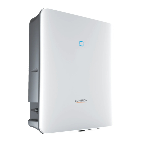
Product Description 2.1 System Introduction The inverter must only be operated with PV strings with class II protection in • accordance with IEC 61730, application class A. It is not allowed for the posi- tive pole or the negative pole of the PV strings to be grounded. This can cause the inverter to be destroyed. - Page 15 User Manual 2 Product Description f f i i g g u u r r e e 2 2 - - 1 1 Inverter Appearance D D e e s s c c r r i i p p t t i i o o n n N N o o .
-
Page 16: Symbols On The Product
2 Product Description User Manual f f i i g g u u r r e e 2 2 - - 2 2 Dimensions of the Inverter W W ( ( m m m m ) ) H H ( ( m m m m ) ) D D ( ( m m m m ) ) W W e e i i g g h h t t ( ( k k g g ) ) 2.3 Symbols on the Product... -
Page 17: Led Indicator
User Manual 2 Product Description S S y y m m b b o o l l E E x x p p l l a a n n a a t t i i o o n n Danger to life due to high voltages! Only qualified personnel can open and service the inverter. -
Page 18: Pv Energy Storage System (Pv Ess)
Compatible with monocrystalline silicon, poly- PV strings crystalline silicon, and thin-film without grounding. Inverter SH5.0RT / SH6.0RT / SH8.0RT / SH10RT Three-phase Smart Measures the export power and communicates with the inverter via the RS485 port. Energy Meter Utility grid... -
Page 19: Declaration For Back-Up Function
PV modules and batteries. If there is no available power from batteries or PV modules in backup mode, the backup power supply will be automatically ter- minated. SUNGROW shall hold no liability for any consequences arising from failing to observe this instruction. - Page 20 2 Product Description User Manual If the Smart Energy Meter is abnormal or not equipped, the inverter will run normally, however, the battery can be charged but not allowed to discharge. In this case the feed- in power setting will be ineffective, and the DO function for optimized mode will be disabled.
-
Page 21: Parallel System
User Manual 2 Product Description With current No current During night, when the battery is empty, it will enter into standby mode. In this case, the grid will supply all power for loads. With current No current 2.7 Parallel System Maximum five hybrid inverters with the same type can be connected in parallel in the PV ESS via RS485 communication. - Page 22 2 Product Description User Manual f f i i g g u u r r e e 2 2 - - 4 4 Parallel PV ESS (A) Master (B) Slave 1 (C) Slave 2 (D) GRID (E) BACK-UP (F) RS485 Only the inverter GRID terminal can be connected in parallel, the BACK-UP ter- minal and the battery terminal cannot be connected together, they should be connected to the off-grid load and the battery respectively.
-
Page 23: Retrofitting The Existing Pv System
User Manual 2 Product Description Feed-in power control. The feed-in power control function refers to "8.5.1 Feed-in • Limitation". The PV installation power of the master inverter is the total installation power of the system, the slave inverters do not need to set the feed-in power. Ripple Control. - Page 24 2 Product Description User Manual O O f f f f - - g g r r i i d d P P o o r r t t t t o o R R e e t t r r o o f f i i t t t t h h e e E E x x i i s s t t i i n n g g P P V V S S y y s s t t e e m m f f i i g g u u r r e e 2 2 - - 6 6 Off-grid Port to Retrofit the Existing PV System The off-grid port retrofits the existing PV system in order to maximize the use of PV en- ergy by allowing the PV inverter to work even when off-grid.
-
Page 25: Function Description
Function Description 3.1 Safety Function 3.1.1 Protection Several protective functions are integrated in the inverter, including short circuit protec- tion, grounding insulation resistance surveillance, residual current protection, anti-is- landing protection, DC overvoltage / over-current protection, etc. 3.1.2 Earth Fault Alarm The inverter has integrated a multiple-function dry-contact (DO relay), which can be used for the external alarm for earth fault. -
Page 26: Drm ("Au"/"Nz")
3 Function Description User Manual power factor (when values out of the rated values) • high altitude • 3.2.2 DRM (“AU”/“NZ”) The inverter provides a terminal block for connecting to a demand response enabling device (DRED). The DRED asserts demand response modes (DRMs). The inverter de- tects and initiates a response to all supported demand response commands within 2s. -
Page 27: Regular Operational Frequency Range
3.3 Battery Management Li-ion battery from SUNGROW, LG Chem, BYD and Pylontech are compatible with the PV ESS,further battery models will be made compatible in the furture. The currently supported battery brands and models are shown in the following table. - Page 28 The table is continually updated. If the battery model is not in the table, consult SUNGROW if it is supported. To maximize the battery life, the inverter will perform battery charge, discharge, and bat- tery maintenance based on the battery status communicated by the BMS.
-
Page 29: Charge Management
User Manual 3 Function Description P P o o r r t t V V o o l l t t a a g g e e / / S S O O C C T T y y p p e e E E m m p p t t y y N N o o r r m m a a l l F F u u l l l l... -
Page 30: Discharge Management
T T r r i i g g g g e e r r S S O O C C F F i i n n i i s s h h i i n n g g S S O O C C SUNGROW SOC ≤ 2 % SOC ≥... -
Page 31: Communication And Configuration
User Manual 3 Function Description The maximum allowable discharge current is limited to the smaller value among the following: the maximum discharge current of the inverter (30A); • the maximum / recommended discharge current from the battery manufacturer. • For this reason, the battery discharge power may not reach the nominal power. If the PV voltage is higher than the upper limit value of MPP voltage (1000 •... -
Page 32: Unpacking And Storage
Check the inner contents for damage after unpacking. • Contact SUNGROW or the transport company in case of any damage or incomplete- ness, and provide photos to facilitate services. Do not dispose of the original packing case. It is recommended to store the device in the... -
Page 33: Scope Of Delivery
User Manual 4 Unpacking and Storage 4.2 Scope of Delivery f f i i g g u u r r e e 4 4 - - 1 1 Scope of delivery I I t t e e m m N N a a m m e e Q Q u u a a n n t t i i t t y y Inverter Wall-mounting bracket... -
Page 34: Inverter Storage
4 Unpacking and Storage User Manual 4.3 Inverter Storage Proper storage is required if the inverter is not installed immediately. Store the inverter in the original packing case with the desiccant inside. • The storage temperature must be always between -30℃ and +70℃, and the storage •... -
Page 35: Mechanical Mounting
Mechanical Mounting 5.1 Safety during Mounting Make sure there is no electrical connection before installation. In order to avoid electric shock or other injury, make sure that holes will not be drilled over any electricity or plumbing installations. Risk of injury due to improper handling Always follow the instructions when moving and positioning the inverter. -
Page 36: Carrier Requirements
5 Mechanical Mounting User Manual The ambient temperature and relative humidity must meet the following • requirements. Avoid direct exposure to sun, rain and snow. • The inverter should be well ventilated. Ensure air circulation. • Never install the inverter in living areas. The inverter will generate noise during opera- •... -
Page 37: Installation Tools
User Manual 5 Mechanical Mounting In case of multiple inverters, reserve specific clearance between the inverters. Install the inverter at an appropriate height for ease of viewing LED indicator and operat- ing switch(es). 5.3 Installation Tools Installation tools include but are not limited to the following recommended ones. If nec- essary, use other auxiliary tools on site. -
Page 38: Moving The Inverter
5 Mechanical Mounting User Manual Hammer drill Marker Vacuum cleaner Rubber mallet (φ10) Wrist strap Wire cutter Wire stripper Hydraulic plier Heat gun MC4 terminal Multimeter MC4 terminal crimping pliers wrench ≥ 1000V DC 4–6mm Wrench RJ45 crimping tool (16 mm, 46 mm) 5.4 Moving the Inverter Before installation, remove the inverter from the packing case and move it to the installa- tion site. -
Page 39: Installing The Inverter
User Manual 5 Mechanical Mounting 5.5 Installing the Inverter Install the inverter on the wall using the provided wall-mounting bracket and expansion plug sets. The expansion plug set shown below is recommended for the installation. (2) Expansion tube (3) Fender washer (1) Self-tapping (4) Spring washer screw... - Page 40 5 Mechanical Mounting User Manual - - - - E E n n d d...
-
Page 41: Electrical Connection
Electrical Connection 6.1 Safety Instructions Prior to any electrical connections, keep in mind that the inverter has dual power sup- plies. It is mandatory for the qualified personnel to wear personal protective equipments (PPE) during the electrical work. Danger to life due to a high voltage inside the inverter! The PV string will generate lethal high voltage when exposed to sunlight. - Page 42 6 Electrical Connection User Manual f f i i g g u u r r e e 6 6 - - 1 1 Terminals at the Bottom of the Inverter * The image shown here is for reference only. The actual product received may differ. D D e e s s c c r r i i p p t t i i o o n n N N o o .
-
Page 43: Electrical Connection Overview
User Manual 6 Electrical Connection table 6-2 The label description of COM terminal D D e e s s c c r r i i p p t t i i o o n n N N o o . . L L a a b b e e l l Connect to the Smart Energy Meter.(If installing a •... - Page 44 6 Electrical Connection User Manual (A) Router (B) Battery (C) PV string (D) Inverter (E) AC circuit breaker (F) Smart Energy Meter (G) Grid (H) Backup loads (I) Monitoring device table 6-3 Cable requirements S S p p e e c c i i f f i i c c a a t t i i o o n n N N o o .
- Page 45 User Manual 6 Electrical Connection N N O O . . S S H H 5 5 . . 0 0 / / 6 6 . . 0 0 R R T T S S H H 8 8 . . 0 0 / / 1 1 0 0 R R T T ①...
- Page 46 6 Electrical Connection User Manual N N O O . . S S H H 5 5 . . 0 0 / / 6 6 . . 0 0 R R T T S S H H 8 8 . . 0 0 / / 1 1 0 0 R R T T ①...
-
Page 47: Additional Grounding Connection
The ground connection of this additional grounding terminal cannot replace • the connection of the PE terminal of the AC cable. Make sure those terminals are both grounded reliably. SUNGROW shall not be held liable for any dam- age caused by the violation. 6.4.1 Additional Grounding Requirements All non-current carrying metal parts and device enclosures in the PV power system should be grounded, for example, mounts of PV modules and the inverter enclosure. -
Page 48: Ac Cable Connection
6 Electrical Connection User Manual (1) Heat shrink tubing (2) OT/DT terminal step 2 Remove the screw on the grounding terminal and fasten the cable with a screwdriver. step 3 Apply paint to the grounding terminal to ensure corrosion resistance. - - - - E E n n d d 6.5 AC Cable Connection 6.5.1 AC Side Requirements... -
Page 49: Assembling The Ac Connector
R R e e c c o o m m m m e e n n d d e e d d S S p p e e c c i i f f i i c c a a t t i i o o n n I I n n v v e e r r t t e e r r M M o o d d e e l l SH5.0RT 25 A SH6.0RT... - Page 50 6 Electrical Connection User Manual step 3 Take out the terminal plug from the housing. step 4 Thread the AC cable of appropriate length through the swivel nut and the housing. step 5 Strip 80 mm ~ 90 mm of the cable jacked and 12 mm of the wire insulation. step 6 ( ( O O p p t t i i o o n n a a l l ) ) When using a multi-core multi-strand copper wire cable, connect the AC wire head to the cord end terminal (hand-tight).
-
Page 51: Installing The Ac Connector
User Manual 6 Electrical Connection Select appropriate cord end terminal according to the cable cross-section area. step 7 Fix all the wires to the terminal plug according to the assignment and tighten to a torque of 1.2 N•m–1.5 N•m with a screwdriver. Then push the terminal plug into the housing until there is an audible click. - Page 52 6 Electrical Connection User Manual step 1 Disconnect the AC circuit breaker and secure it against reconnection. step 2 Remove the waterproof lid from the G G R R I I D D terminal. step 3 Insert the AC connector into the G G R R I I D D terminal on the bottom of the inverter until there is an audible sound.
-
Page 53: Dc Cable Connection
User Manual 6 Electrical Connection Insert block ① into AC connector ② from the side. Tighten the screw on the bottom of block ①. step 5 Connect PE cable to ground. step 6 Connect phase cable and “N” cable to AC circuit breaker. step 7 Connect AC circuit breaker to utility grid. -
Page 54: Pv Input Configuration
6 Electrical Connection User Manual 6.6.1 PV Input Configuration In Australia and New Zealand, ensure the DC power for any PV string never exceeds a certain level with regards to the string voltage to avoid derating: ≤ 12.5 kW if string voltage is lower than 500 V ≤... -
Page 55: Assembling The Pv Connectors
Do not connect the AC circuit breaker before finishing electrical connection. • SUNGROW provides corresponding PV connectors in the scope of delivery for quick connection of PV inputs. To ensure IP65 protection, use only the sup- plied connector or the connector with the same ingress of protection. -
Page 56: Installing The Pv Connector
6 Electrical Connection User Manual 1: Positive crimp contact 2:Negative crimp contact step 3 Lead the cable through cable gland, and insert the crimp contact into the insulator until it snaps into place. Gently pull the cable backward to ensure firm connection. Tighten the cable gland and the insulator (torque 2.5 N.m to 3 N.m). - Page 57 Arc or contactor over-temperature may occur if the PV connectors are not • firmly connected in place, and SUNGROW shall not be held liable for any damage caused due to this operation. step 4 Follow the foregoing steps to connect PV connectors of other PV strings.
-
Page 58: Communication Connection
6 Electrical Connection User Manual 6.7 Communication Connection L L A A N N f f u u n n c c t t i i o o n n Through the Modbus TCP/IP protocol, the EMS or the Logger from the third party •... - Page 59 User Manual 6 Electrical Connection step 2 Unscrew the swivel nut from the connector. step 3 Remove the inner rubber gasket. step 4 Insert the RJ45 plug into the front plug connector until there is an audible click, and in- stall the rubber gasket.
-
Page 60: Winet-S Connection
6 Electrical Connection User Manual step 2 Insert the LAN connector into L L A A N N terminal on the bottom of the inverter. step 3 Pull cables outwards to confirm whether they are fastened firmly, then tighten the swivel nut with appropriate torque. - Page 61 User Manual 6 Electrical Connection (A) Inverter (B) Router/Switch (C) iSolarCloud server (D) iSolarCloud App (E) iSolarCloud (1) Internet (2) Local access (3) Remote For details, see the quick guide for the WiNet-S module. Scan the following QR code for the quick guide.
- Page 62 6 Electrical Connection User Manual step 3 Unscrew the housing from the communication module. step 4 Thread the network cable through the swivel nut and gasket. Afterwards, route the cable into the opening of the sealing. Finally, insert the cable through the housing. step 5 Insert the RJ45 plug into the front plug connector until there is an audible click and tight- en the housing.
-
Page 63: Rs485 Connection
User Manual 6 Electrical Connection step 7 Slightly shake it by hand to determine whether it is installed firmly. - - - - E E n n d d 6.7.2.2 WLAN Communication step 1 Remove the waterproof lid from the W W L L A A N N terminal. step 2 Install the module. - Page 64 6 Electrical Connection User Manual 6.7.3.1 Assembling the COM Connector step 1 Unscrew the swivel nut from the connector. step 2 Take out the terminal block. step 3 Remove the seal and lead the cable through the cable gland. step 4 Remove the cable jacket and strip the wire insulation.
- Page 65 User Manual 6 Electrical Connection step 5 Plug the wires into the R R S S 4 4 8 8 5 5 terminal according the labels on the bottom of the inverter. step 6 Pull the wires outward to check whether they are firmly installed. step 7 Insert the terminal block into the connector until it snaps into place with an audible click.
-
Page 66: Smart Energy Meter Connection
For the setting of feed-in power limit, refer to the section "8.5.1 Feed- Limitation". Contact SUNGROW to ensure that the Smart Energy Meter model is available locally. This section mainly describes the cable connections on the inverter side. Refer to the quick guide delivered with the Smart Energy Meter for the connections on the meter side. -
Page 67: Battery Connection
User Manual 6 Electrical Connection 6.9 Battery Connection This section mainly describes the cable connections on the inverter side. Refer to the in- structions supplied by the battery manufacturer for the connections on the battery side and configuration. Only use properly insulated tools to prevent accidental electric shock or short circuits. - Page 68 6 Electrical Connection User Manual f f i i g g u u r r e e 6 6 - - 3 3 SUNCLIX Connector Components 3: Insert 1:Spring 2: Sleeve 4: Cable gland step 1 Strip the insulation from the cable by 15 mm. step 2 Pry the connection open and pull the sleeve and the insert apart.
-
Page 69: Connecting The Can Cable
6.9.2 Connecting the CAN Cable The CAN cable enables the communication between the inverter and the Li-ion battery from SUNGROW, BYD and Pylontech. P P r r o o c c e e d d u u r r e e For detailed connection description of the CAN cable, refer to the section "6.7.3 RS485... -
Page 70: Do Connection
6 Electrical Connection User Manual P P r r o o c c e e d d u u r r e e For detailed connection description of the RS485 cable, refer to the section "6.7.3 RS485 Connection". For detailed connection description of the Enable cable, refer to the section "6.7.3 RS485 Connection". -
Page 71: Di Connection
User Manual 6 Electrical Connection An AC contactor must be installed between the inverter and appliances. It is • forbidden to connect the load directly to the DO port. The current of the DO dry contact should not be larger than 3 A. •... -
Page 72: Assembling The Com Connector
6 Electrical Connection User Manual The switches that need to be closed in the state of DRM0 ~ DRM8 are shown in the table below. D D e e m m a a n n d d R R e e s s p p o o n n s s e e M M o o d d e e O O p p e e r r a a t t i i o o n n a a l l I I n n s s t t r r u u c c t t i i o o n n S S w w i i t t c c h h s s t t a a t t e e DRM0... - Page 73 User Manual 6 Electrical Connection step 2 Take out the terminal block. step 3 Remove the seal and lead the cable through the cable gland. step 4 Remove the cable jacket by 7 mm–10 mm. step 5 Plug the wires into the corresponding terminal according the labels on the bottom of the inverter.
-
Page 74: Installing The Com Connector
6 Electrical Connection User Manual step 6 Pull the wires outward to check whether they are firmly installed. step 7 Insert the terminal block into the connector until it snaps into place with an audible click. step 8 Fasten the swivel nut. - - - - E E n n d d 6.11.2 Installing the COM Connector step 1 Remove the waterproof lid from the C C O O M M terminal. -
Page 75: Backup Connection
User Manual 6 Electrical Connection step 3 Pull cables outwards to confirm whether they are fastened firmly. step 4 Connect the other end to the DRED / Ripple Control Receiver device. - - - - E E n n d d 6.12 Backup Connection step 1 Assembling the BACK-UP Connector. - Page 76 6 Electrical Connection User Manual step 4 Pull all the lines outward to check whether they are firmly installed. - - - - E E n n d d...
-
Page 77: Commissioning
Commissioning 7.1 Inspection before Commissioning Check the following items before starting the inverter: All the installation sites are convenient for operation, maintenance and service. • All devices are firmly installed. • Space for ventilation is sufficient for one inverter or multiple inverters. •... -
Page 78: App Preparation
2 Register an account. Refer to "8.3 Account Registration". If you have got the account and password from the distributor/installer or SUNGROW, skip this step. step 3 Download the firmware package to the mobile device in advance. Refer to "8.10.11 Firmware Update". - Page 79 User Manual 7 Commissioning f f i i g g u u r r e e 7 7 - - 2 2 Creating Power Plant step 4 Select plant type to R R E E S S I I D D E E N N T T I I A A L L and inverter type to H H Y Y B B R R I I D D . f f i i g g u u r r e e 7 7 - - 3 3 Selecting Plant/Inverter Type step 5 Scan the QR code on the communication device or manually enter the serial number of the communication device.
- Page 80 7 Commissioning User Manual f f i i g g u u r r e e 7 7 - - 5 5 Selecting Internet Access Mode step 7 The E E A A S S Y Y C C O O N N N N E E C C T T I I N N S S T T R R U U C C T T I I O O N N screen will prompt. Press the multi-function but- ton on the WiNet-S module once to turn on EasyConnect mode.
-
Page 81: Initializing The Device
User Manual 7 Commissioning 7.5 Initializing the Device The inverter is successfully connected to the router. If there is no latest equipment upgrade package, skip steps 1 and 2. The actual initializing procedure may differ due to different countries. Please follow the actual App guidance. -
Page 82: Configuring The Plant
7 Commissioning User Manual step 4 When the country is set to Australia, additionally set the applicable network service pro- vider and then the grid type. The image shown here is for reference only. Refer to the actual interface for the sup- ported network service providers. - Page 83 User Manual 7 Commissioning The distributor/installer who creates a plant for the end user needs to get the end user's e-mail address. In configuring a plant, the e-mail address is required, and each e-mail address can be registered only once. step 1 The App screen will display the added inverter.
- Page 84 7 Commissioning User Manual f f i i g g u u r r e e 7 7 - - 1 1 3 3 Entering Tariff Information step 4 Fill in the end user's e-mail address. The first time you fill in the end user's e-mail ad- dress, the system will create an account for the end user and send an email to the end user.
- Page 85 7 7 - - 1 1 6 6 Live Data View Function Setting Consult Sungrow service for the devices that support live data function. step 7 Tab B B A A C C K K to the C C O O M M P P L L E E T T E E D D screen. Tab P P D D F F R R E E P P O O R R T T to export the plant configu-...
- Page 86 7 Commissioning User Manual step 8 Tab B B A A C C K K to the C C O O M M P P L L E E T T E E D D screen. Tab D D A A S S H H B B O O A A R R D D to return and manually re- fresh the page until the newly created plant is displayed with status commissioned.
-
Page 87: Isolarcloud App
Users can also view inverter information and set parameters through the App. * To achieve direct login via WLAN, the wireless communication module developed and manufactured by SUNGROW is required. The iSolarCloud App can also establish com- munication connection to the inverter via Ethernet connection. -
Page 88: Account Registration
8 iSolarCloud App User Manual 8.3 Account Registration The account distinguishes two user groups, end user and distributor/installer. The end user can view plant information, create plants, set parameters, share plants, • etc. The distributor/installer can help the end user to create plants, manage, install, or •... -
Page 89: Login
User Manual 8 iSolarCloud App The code of upper level distributor/installer can be obtained from the upper level distributor/installer. Only when your organization belongs to the upper level distributor/installer organization, can you fill in the corresponding code. step 4 Tick A A c c c c e e p p t t p p r r i i v v a a c c y y p p r r o o t t o o c c o o l l and tap R R e e g g i i s s t t e e r r to finish the registration operation. - - - - E E n n d d 8.4 Login 8.4.1 Requirements... - Page 90 8 iSolarCloud App User Manual f f i i g g u u r r e e 8 8 - - 3 3 WLAN Local Access step 5 If the inverter is not initialized, navigate to the quick setting screen to initialize the protec- tion parameters.
-
Page 91: Initial Settings
User Manual 8 iSolarCloud App - - - - E E n n d d 8.5 Initial Settings 8.5.1 Feed-in Limitation The function of the feed-in limitation is to control the amount of power injected in the grid by the plant. In some situations,this function is also called as E E x x p p o o r r t t l l i i m m i i t t a a t t i i o o n n or Z Z e e r r o o e e x x p p o o r r t t . - Page 92 8 iSolarCloud App User Manual table 8-2 Descriptions of reactive power regulation mode: D D e e s s c c r r i i p p t t i i o o n n s s M M o o d d e e The PF is fixed at +1.000.
- Page 93 User Manual 8 iSolarCloud App D D e e f f a a u u l l t t E E x x p p l l a a n n a a t t i i o o n n R R a a n n g g e e P P a a r r a a m m e e t t e e r r D D E E...
-
Page 94: Function Overview
8 iSolarCloud App User Manual D D e e f f a a u u l l t t E E x x p p l l a a n n a a t t i i o o n n R R a a n n g g e e P P a a r r a a m m e e t t e e r r D D E E... -
Page 95: Home
User Manual 8 iSolarCloud App f f i i g g u u r r e e 8 8 - - 7 7 App Function Tree Map 8.7 Home Home page of the App is shown in the following figure. f f i i g g u u r r e e 8 8 - - 8 8 Home table 8-5 Home page description D D e e s s c c r r i i p p t t i i o o n n... -
Page 96: Run Information
8 iSolarCloud App User Manual D D e e s s c c r r i i p p t t i i o o n n N N o o . . N N a a m m e e D D i i r r e e c c t t P P o o w w e e r r C C o o n n - - Shows electricity directly consumed by loads s s u u m m p p t t i i o o n n o o f f T T o o d d a a y y... -
Page 97: Chart
User Manual 8 iSolarCloud App f f i i g g u u r r e e 8 8 - - 1 1 0 0 Records On R R e e c c o o r r d d s s screen, users can view chart and check fault alarm record. 8.9.1 Chart Tap C C h h a a r r t t to enter the screen showing daily power generation, as shown in the following figure. -
Page 98: Fault Alarm Record
8 iSolarCloud App User Manual I I t t e e m m D D e e s s c c r r i i p p t t i i o o n n Annual power generation Indicates annual power generation, charging, feed-in histogram power, and direct consumption power Total power generation... -
Page 99: System Parameters
User Manual 8 iSolarCloud App f f i i g g u u r r e e 8 8 - - 1 1 4 4 More The M M o o r r e e screen supports the following operations: Set parameters including inverter system parameters and energy management •... -
Page 100: Running Time
8 iSolarCloud App User Manual D D a a t t e e / / T T i i m m e e The correct system time is very important. Wrong system time will directly affect the da- ta logging and power generation value. The clock is in 24-hour format. 8.10.2 Running Time Tap S S e e t t t t i i n n g g s s →... -
Page 101: Off-Grid Parameters
User Manual 8 iSolarCloud App 8.10.4 Off-grid Parameters Tap S S e e t t t t i i n n g g s s → → O O p p e e r r a a t t i i o o n n P P a a r r a a m m e e t t e e r r s s → → O O f f f f - - g g r r i i d d P P a a r r a a m m e e t t e e r r s s to enter the screen, as shown in the following figure. -
Page 102: Reactive Power Regulation
8 iSolarCloud App User Manual D D e e s s c c r r i i p p t t i i o o n n R R a a n n g g e e P P a a r r a a m m e e t t e e r r D D e e f f a a u u l l t t A A c c t t i i v v e e P P o o w w e e r r R R i i s s - - Rising gradient of inverter active... -
Page 103: Battery Forced Charge Time
User Manual 8 iSolarCloud App f f i i g g u u r r e e 8 8 - - 2 2 1 1 Battery Discharge Time 8.10.8 Battery Forced Charge Time Tap S S e e t t t t i i n n g g s s → → E E n n e e r r g g y y M M a a n n a a g g e e m m e e n n t t P P a a r r a a m m e e t t e e r r → → B B a a t t t t e e r r y y F F o o r r c c e e d d C C h h a a r r g g e e T T i i m m e e to enter the corresponding screen. - Page 104 8 iSolarCloud App User Manual f f i i g g u u r r e e 8 8 - - 2 2 3 3 Load Control T T i i m m i i n n g g M M o o d d e e In this mode, set the L L o o a a d d T T i i m m i i n n g g S S t t a a r r t t T T i i m m e e 1 1 and L L o o a a d d T T i i m m i i n n g g E E n n d d T T i i m m e e 1 1 , the sys- tem will control the load operation during the interval.
-
Page 105: Communication Parameters
User Manual 8 iSolarCloud App When the inverter is installed to retrofit an exisiting PV system, the upper limit of opti- • mized power is the sum of the rated power of the hybrid inverter and the rated power of the existing PV inverter. Once the intelligent mode is enabled, the DO relay will remain connected for 20 mi- •... -
Page 106: Firmware Update
8 iSolarCloud App User Manual 8.10.11 Firmware Update To avoid download failure due to poor on-site network signal, it is recommended to download the firmware package to the mobile device in advance. step 1 Enable the "Mobile data" of the mobile device. step 2 Open the App, tap at the upper right corner and select F F i i r r m m w w a a r r e e D D o o w w n n l l o o a a d d . -
Page 107: Grounding Detection
- - - - E E n n d d 8.10.12 Grounding Detection Contact SUNGROW to obtain the advanced account and corresponding pass- word before setting the earth detection parameters. Unauthorized personnel are not allowed to log in with this account. Otherwise, SUNGROW shall not be held liable for any damages caused. -
Page 108: Frequency Shift Power Control
8 iSolarCloud App User Manual R R a a n n g g e e P P a a r r a a m m e e t t e e r r D D e e f f a a u u l l t t v v a a l l u u e e M M a a s s t t e e r r - - s s l l a a v v e e o o p p e e r r a a t t i i o o n n ON / OFF m m o o d d e e... -
Page 109: System Decommissioning
System Decommissioning 9.1 Decommissioning the Inverter 9.1.1 Disconnecting the Inverter For maintenance or other service work, the inverter must be switched off. Proceed as follows to disconnect the inverter from the AC and DC power sources. Lethal voltages or damage to the inverter will follow if otherwise. step 1 Stop the inverter via the iSolarCloud App. -
Page 110: Dismantling The Inverter
9 System Decommissioning User Manual step 9 Lay the tool in the location of snap and press the tool down to remove the AC connector. Ensure that the AC wiring terminals are voltage-free via a multimeter, and remove the AC wires and communication wires. step 10Use the multimeter to measure the port voltage of the battery. -
Page 111: Decommissioning The Battery
4 Wait for about 1 minute and then use the multimeter to measure the port voltage of the battery. step 5 If the battery port voltage is zero, disconnect the power cables from the battery module. - - - - E E n n d d SUNGROW is not liable for disposal of the battery. -
Page 112: Troubleshooting And Maintenance
3. Check whether the cross-sectional area of the AC cable meets the requirement. 4. If the alarm persists, contact SUNGROW. Generally, the inverter will be reconnected to the grid after the grid recovers. If the alarm occurs frequently: 1. - Page 113 2. Check, through the App, whether the protection parameters are appropriately set. 3. If the alarm persists, contact SUNGROW. Generally, the inverter will be reconnected to the grid after the grid recovers. If the alarm occurs frequently: 1.
- Page 114 App. 3. If the alarm persists, contact SUNGROW. 1. Check whether the corresponding string is of re- verse polarity. If so, disconnect the DC switch and adjust the polarity when the solar radiation is low and the string current drops below 0.5A.
- Page 115 If the fault persists, check it again when the weather turns fine. 5. If the alarm persists, contact SUNGROW. 1. Check whether the AC cable is correctly connected.
- Page 116 Battery 732–736, connected. If so, contact the battery manufacturer. 739, 832– abnormal If not,contact SUNGROW. 833, 835– 3. In case of abnormal battery temperature, take measures to change the ambient temperature, such as improving heat dissipation conditions. 4. If the fault persists, contact battery manufacturer.
- Page 117 507, 508, System alarm ambient environment is abnormal. If so, take cor- 510, 513, rective measures. 516–518 2. If the alarm persists, contact SUNGROW. 006, 007, 011, 019, 021, 025, 038, 040– 042, 048– 050, 052–...
-
Page 118: Maintenance
As the inverter contains no component parts that can be maintained, never • arbitrarily replace any internal components. For any maintenance need, please contact SUNGROW. Otherwise, SUN- • GROW shall not be held liable for any damage caused. Servicing of the device in accordance with the manual should never be under- taken in the absence of proper tools, test equipments or the latest revision of the manual which has been clearly and thoroughly understood. -
Page 119: Routine Maintenance
Lethal voltage still exists in the inverter. Please wait at least 10 minutes and then perform maintenance work. There is a button cell on the inner PCB board. Contact SUNGROW for replacement when the relevant fault alarm occurs. Check the fastener, appearance, voltage, and resistance quarterly and annually. -
Page 120: Appendix
11 Appendix 11.1 Technical Data P P a a r r a a m m e e t t e e r r s s S S H H 5 5 . . 0 0 R R T T S S H H 6 6 . . 0 0 R R T T P P V V I I n n p p u u t t Max. - Page 121 User Manual 11 Appendix P P a a r r a a m m e e t t e e r r s s S S H H 5 5 . . 0 0 R R T T S S H H 6 6 . . 0 0 R R T T 270 Vac ...
- Page 122 11 Appendix User Manual P P a a r r a a m m e e t t e e r r s s S S H H 5 5 . . 0 0 R R T T S S H H 6 6 . . 0 0 R R T T Plug and play connector AC connection type M M e e c c h h a a n n i i c c a a l l D D a a t t a a...
- Page 123 User Manual 11 Appendix P P a a r r a a m m e e t t e e r r s s S S H H 8 8 . . 0 0 R R T T S S H H 1 1 0 0 R R T T Max.
- Page 124 11 Appendix User Manual P P a a r r a a m m e e t t e e r r s s S S H H 8 8 . . 0 0 R R T T S S H H 1 1 0 0 R R T T Parallel operation on grid port / Max.
-
Page 125: The Compatibility For Backup Under Off-Grid Scenario
Conditioner (Fre- 1.5P quency conversion) The data of the compatibility for backup of SH5.0RT / SH6.0RT / SH8.0RT / SH10RT are based on the test with SUNGROW SBR096/128/160/192/224/ 256 batteries (-20 ~ 53 ℃, 5~100% SOC). For the actual application, please refer to the maximum output capacity of the battery used. -
Page 126: Quality Assurance
E E x x c c l l u u s s i i o o n n o o f f L L i i a a b b i i l l i i t t y y In the following circumstances, SUNGROW has the right to refuse to honor the quality guarantee: The free warranty period for the whole machine/components has expired. - Page 127 C C h h i i n n a a ( ( H H Q Q ) ) A A u u s s t t r r a a l l i i a a Sungrow Australia Group Pty. Ltd. Sungrow Power Supply Co., Ltd...
- Page 128 R R o o m m a a n n i i a a T T u u r r k k e e y y Service Partner - Elerex Sungrow Deutschland GmbH Turkey service@sungrow-emea.com Istanbul +90 216 663 61 80 service@sungrow-emea.com...
Need help?
Do you have a question about the SH5.0RT and is the answer not in the manual?
Questions and answers