Sungrow SH8.0RT User Manual
3-phase hybrid inverter
Hide thumbs
Also See for SH8.0RT:
- User manual (128 pages) ,
- Quick installation manual (44 pages) ,
- Installation & commissioning (3 pages)
Table of Contents

Subscribe to Our Youtube Channel
Related Manuals for Sungrow SH8.0RT


Summary of Contents for Sungrow SH8.0RT
- Page 1 User Manual 3–Phase Hybrid Inverter SH5.0RT/SH6.0RT/SH8.0RT/SH10RT/SH5.0RT-20/ SH6.0RT-20/SH8.0RT-20/SH10RT-20 SH5.0RT/ SH6.0RT/SH8.0RT/SH10RT/ SH5.0RT-20/SH6.0RT-20/SH8.0RT- 20/SH10RT-203–Phase Hybrid Inverter User ManualSH5.0– 10RT&SH5.0–10RT-20-UEN-Ver20- 202212 SH5.0–10RT&SH5.0–10RT-20-UEN-Ver20-202212...
-
Page 3: All Rights Reserved
Software Licenses • It is prohibited to use data contained in firmware or software developed by SUNGROW, in part or in full, for commercial purposes by any means. • It is prohibited to perform reverse engineering, cracking, or any other operations that... -
Page 4: About This Manual
Please read this manual carefully before using the product and keep it properly at a place for easy access. All contents, pictures, marks, and symbols in this manual are owned by SUNGROW. No part of this document may be reprinted by the non-internal staff of SUNGROW without written... - Page 5 Contents of this manual may be periodically updated or revised, and the actual product pur- chased shall prevail. Users can obtain the latest manual from support.sungrowpower.com or sales channels. Symbols This manual contains important safety instructions, which are highlighted with the following symbols, to ensure personal and property safety during usage, or to help optimize the prod- uct performance in an efficient way.
-
Page 7: Table Of Contents
Contents All Rights Reserved .....................I About This Manual......................II 1 Safety Instructions ....................1 1.1 Unpacking and Inspection ................2 1.2 Installation Safety ...................2 1.3 Electrical Connection Safety................3 1.4 Operation Safety ....................5 1.5 Maintenance Safety ..................5 1.6 Disposal Safety ....................6 2 Product Description ..................7 2.1 System Introduction ..................7 2.2 Product Introduction..................7... - Page 8 3.2.2 DRM (“AU”/“NZ”).................25 3.2.3 Regular Operational Voltage Range .............25 3.2.4 Regular Operational Frequency Range ..........26 3.2.5 Reactive Power Regulation..............26 3.2.6 Load Control..................26 3.3 Battery Management ..................26 3.3.1 Charge Management................28 3.3.2 Discharge Management...............29 3.4 Communication and Configuration ..............30 3.5 EV Charger Management................30 4 Unpacking and Storage .................31 4.1 Unpacking and Inspection ................31...
- Page 9 6.6.1 PV Input Configuration ................57 6.6.2 Assembling the PV Connectors ............58 6.6.3 Installing PV Connector ...............59 6.7 Communication Connection ................61 6.7.1 Ethernet Connection................61 6.7.2 WiNet-S Connection................63 6.7.3 RS485 Connection ................66 6.8 Smart Energy Meter Connection ..............69 6.9 Battery Connection ..................70 6.9.1 Connecting the Power Cable..............71 6.9.2 Connecting the CAN Cable ..............75 6.9.3 Connecting the Enable Cable...............75...
- Page 10 8.9 Records ..................... 103 8.9.1 Chart....................103 8.9.2 Fault Alarm Record ................104 8.9.3 Event Records .................. 105 8.10 Inverter (Optional)..................106 8.11 EV-Charger (Optional)................107 8.11.1 Driving Distance Per kWh..............109 8.11.2 Charging Mode................109 8.11.3 Parameter Setting ................114 8.11.4 Start/Stop Switch................
- Page 11 10.1 Troubleshooting..................134 10.2 Maintenance .................... 139 10.2.1 Maintenance Notices ............... 139 10.2.2 Routine Maintenance............... 140 10.2.3 Replacing the Button Cell..............140 11 Appendix ...................... 142 11.1 Technical Data ..................142 11.2 The Compatibility for Backup under Off-grid Scenario ........153 11.3 Quality Assurance..................
-
Page 13: Safety Instructions
Perform operations considering ac- tual onsite conditions. • SUNGROW shall not be held liable for any damage caused by violation of gen- eral safety operation requirements, general safety standards, or any safety in- struction in this manual. -
Page 14: Unpacking And Inspection
If there are problems with the above inspection items, do not install the device and contact your distributor first. If the problem persists, con- tact SUNGROW in time. Installation Safety •... -
Page 15: Electrical Connection Safety
User Manual 1 Safety Instructions Electrical Connection Safety Before electrical connections, please make sure that the inverter is not damaged, otherwise it may cause danger! Before electrical connections, please make sure that the inverter switch and all switches connected to the inverter are set to "OFF", otherwise electric shock may occur! The PV string will generate lethal high voltage when exposed to sunlight. - Page 16 1 Safety Instructions User Manual Damage to the product caused by incorrect wiring is not covered by the warranty. • Electrical connection must be performed by professionals. • Please use measuring devices with an appropriate range. Overvoltage can dam- age the measuring device and cause personal injury. •...
-
Page 17: Operation Safety
User Manual 1 Safety Instructions Operation Safety When routing cables, ensure a distance of at least 30 mm between the cables and heat-generating components or areas to protect the insulation layer of cables from aging and damage. When the product is working: •... -
Page 18: Disposal Safety
To avoid the risk of electric shock, do not perform any other maintenance opera- tions beyond those described in this manual. If necessary, contact your distributor first. If the problem persists, contact SUNGROW. Otherwise, the losses caused is not covered by the warranty. -
Page 19: Product Description
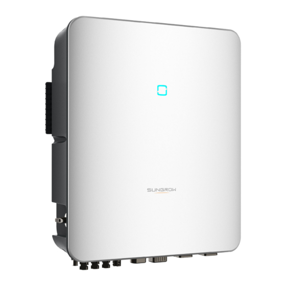
Product Description System Introduction • The inverter must only be operated with PV strings with class II protection in ac- cordance with IEC 61730, application class A. It is not allowed for the positive pole or the negative pole of the PV strings to be grounded. This can cause the inverter to be destroyed. - Page 20 2 Product Description User Manual figure 2-1 Inverter Appearance Description Name LED indicator panel Indicates the current working state of the inverter. Used to disconnect PV - only when there is no PV DC switch(Optional) production. Includes DC terminals, AC terminals, battery terminals, Electrical connection communication terminals and additional grounding area...
-
Page 21: Symbols On The Product
User Manual 2 Product Description figure 2-2 Dimensions of the Inverter Weight(kg) W(mm) H(mm) D(mm) Symbols on the Product Symbol Explanation RCM mark of conformity. TÜV mark of conformity. CE mark of conformity. EU/EEA Importer Do not dispose of the inverter together with household waste. The inverter does not have a transformer. -
Page 22: Led Indicator
2 Product Description User Manual Symbol Explanation Danger to life due to high voltages! Only qualified personnel can open and service the inverter. Do not touch live parts for 10 minutes after disconnection from the power sources. Additional grounding point. LED Indicator The LED indicator on the front of the inverter indicates the working state of the inverter. -
Page 23: Pv Energy Storage System (Pv Ess)
User Manual 2 Product Description The inverter operates automatically when input and output requirements are met. Rotate the DC switch to the “OFF” position to stop the inverter when a fault occurs. When you need to stop the inverter normally please first turn off AC and shut down the hybrid via app. Turn the DC switch to the “ON”... -
Page 24: Declaration For Back-Up Function
PV modules and batteries. If there is no available power from batteries or PV modules in backup mode, the backup power supply will be automatically terminated. SUNGROW shall hold no liability for any consequences arising from failing to observe this instruction. -
Page 25: Energy Management
User Manual 2 Product Description Normally, the Back-Up switching time is less than 20 ms. However, some external fac- tors or local regulations may cause the system to fail on Back-Up mode. Therefore, the users must be aware of conditions and follow the instructions as below: •... - Page 26 2 Product Description User Manual With current No current Energy Management during Night During night, with energy available, the battery will discharge to supply power for loads. Al- ternatively, the grid will supply power for the loads in case the discharge power of the battery is insufficient.
-
Page 27: Parallel System
User Manual 2 Product Description With current No current Parallel System 2.7.1 Grid-connected Parallel System Maximum five hybrid inverters with the same type can be connected in parallel in the PV ESS via RS485 communication. Each hybrid inverter will independently provide power to loads attached at the backup-port in case of a grid outage. - Page 28 2 Product Description User Manual figure 2-4 Parallel PV ESS (A) Master (B) Slave 1 (C) Slave 2 (D) GRID (E) BACK-UP (F) RS485 Only the hybrid GRID terminals can be connected in parallel, the BACK-UP termi- nals and the battery terminals cannot be connected together. Each hybrid must have its own BACK-UP loads.
-
Page 29: Off-Grid Parallel System
• This section is not applicable for Europe but only for other regions. Please con- tact SUNGROW for details of specific regions and models. In off-grid parallel mode, devices are controlled by the smart switch at the grid-connected point, and relevant parameters can be set on iSolarCloud App. - Page 30 2 Product Description User Manual Only 2~5 inverters can be connected in parallel. If inverters of the same power are con- nected in parallel, the output power is the sum of the power of each inverter. If inverters of different power are connected in parallel, the output power is the product of the minimum power value of a single inverter and the number of inverters.
- Page 31 User Manual 2 Product Description figure 2-7 Wiring diagram for other regions * * Ensure that only the PE cable at the backup port of the master inverter is grounded in re- gions beyond Australia and New Zealand. If there is more than one inverter in the system, the backup terminal of inverters cannot be connected to loads, nor can they be connected in parallel.
-
Page 32: Pv Storage And Ev-Charging System
2 Product Description User Manual • Off-grid mode enabling. Refer to "8.12.5 O_Off-grid_Parameters.dita". The off-grid mode is off by default and can be enabled first when inverters are turned on. • Parallel configuration. Refer to "8.12.14 Parallel Configuration" to configure the master and slave inverters on iSolarCloud App.If there is only one inverter in the system, disable the parallel configuration function. -
Page 33: Retrofitting The Existing Pv System
Remark Item Compatible with monocrystalline silicon, PV strings polycrystalline silicon, and thin-film without grounding. SH5.0RT-20/SH6.0RT-20/SH8.0RT-20/SH10RT- Inverter Three-phase Smart Measures the export power and communicates Energy Meter with the inverter via the RS485 port. Grid grounding system types: TT, TN, TN-C-S, TN-... - Page 34 2 Product Description User Manual On-grid Port to Retrofit the Existing PV System figure 2-9 On-grid Port to Retrofit the Existing PV System The AC terminal of the PV inverter and the GRID terminal of the hybrid inverter are con- nected in parallel.
-
Page 35: Retrofitted Pv Storage And Ev-Charging System
The retrofitted PV storage and charging system is as follows: figure 2-11 Retrofitted PV Storage and EV-Charger System (A) PV Inverter (B) PV Strings (C) SH5.0RT-20/SH6.0RT- 20/SH8.0RT-20/SH10RT- (D) Home Loads (E) EV Charger (F) Smart Energy Meter (G) Utility Grid... -
Page 36: Function Description
Function Description Safety Function 3.1.1 Protection Several protective functions are integrated in the inverter, including short circuit protection, grounding insulation resistance surveillance, residual current protection, anti-islanding pro- tection, DC overvoltage / over-current protection, etc. 3.1.2 Earth Fault Alarm The inverter has integrated a multiple-function dry-contact (DO relay), which can be used for the external alarm for earth fault. -
Page 37: Drm ("Au"/"Nz")
User Manual 3 Function Description • power factor (when values out of the rated values) • high altitude 3.2.2 DRM (“AU”/“NZ”) The inverter provides a terminal block for connecting to a demand response enabling device (DRED). The DRED asserts demand response modes (DRMs). The inverter detects and ini- tiates a response to all supported demand response commands within 2s. -
Page 38: Regular Operational Frequency Range
Battery Management Li-ion battery from SUNGROW, LG Chem, BYD and Pylontech are compatible with the PV ESS,further battery models will be made compatible in the future. The currently supported battery brands and models are shown in the following table. - Page 39 The table is continually updated. If the battery model is not in the table, consult SUNGROW if it is supported. To maximize the battery life, the inverter will perform battery charge, discharge, and battery maintenance based on the battery status communicated by the BMS.
-
Page 40: Charge Management
3 Function Description User Manual Port Voltage / SOC Type Empty Normal Full BYD (Battery-Box 5 %...100 %) Premium HVM / SOC < 5 % SOC = 100 % (by default) HVS) Pylontech (Power- cube-X1/X2/H1/H2) 8 %...100 % SOC < 8 % SOC = 100 % Pylontech (Force (by default) -
Page 41: Discharge Management
The emergency charge command reported to the inverter is cleared. table 3-4 Default SOC Conditions for Li-ion Battery Backup Charge Type Trigger SOC Finishing SOC SUNGROW SOC ≤ 2 % SOC ≥ 4 % LG Chem SOC ≤ 5 % SOC ≥... -
Page 42: Communication And Configuration
3 Function Description User Manual • the maximum discharge current of the inverter (30A); • the maximum / recommended discharge current from the battery manufacturer. For this reason, the battery discharge power may not reach the nominal power. • If the PV voltage is higher than 900 V, the battery cannot discharge. •... -
Page 43: Unpacking And Storage
• Check the inner contents for damage after unpacking. Contact SUNGROW or the transport company in case of any damage or incompleteness, and provide photos to facilitate services. Do not dispose of the original packing case. It is recommended to store the device in the original packing case when the product is decommissioned. -
Page 44: Scope Of Delivery
4 Unpacking and Storage User Manual Scope of Delivery figure 4-1 Scope of delivery Item Name Quantity Inverter Wall-mounting bracket * Expansion plug set M4 screws and washers AC/Backup connector set Block (Optional) Cord end terminal * PV connectors 2 ~ 3 Crimp contact 2 ~ 3 SUNCLIX/Evo2 connector set... -
Page 45: Inverter Storage
User Manual 4 Unpacking and Storage ** SH5.0– 10RT matches DTSU666 smart energy meters, and SH5.0– 10RT-20 matches DTSU666-20 smart energy meters. *** This accessory is only for SH5.0-10RT-20. The Australia and New Zealand region is equipped with 6 x 100A/0.333V CT as standard, and the other areas are equipped with 3 x 100A/0.333V CT as standard. -
Page 46: Mechanical Mounting
Mechanical Mounting Respect all local standards and requirements during mechanical installation. Safety During Mounting Make sure there is no electrical connection before installation. Before drilling, avoid the water and electricity wiring in the wall. Poor installation environment will affect system performance! •... -
Page 47: Location Requirements
User Manual 5 Mechanical Mounting Location Requirements To a large extent, a proper installation location ensures safe operation, service life, and per- formance of the inverter. • The inverter with protection rating IP65 can be installed both indoors and outdoors. •... -
Page 48: Angle Requirements
5 Mechanical Mounting User Manual 5.2.3 Angle Requirements Install the inverter vertically. Never install the inverter horizontally, or at forward/backward tilted, or upside down. 5.2.4 Clearance Requirements Reserve enough clearance around the inverter to ensure sufficient space for heat dissipation. In case of multiple inverters, reserve specific clearance between the inverters. -
Page 49: Installation Tools
User Manual 5 Mechanical Mounting Install the inverter at an appropriate height for ease of viewing LED indicator and operating switch(es). Installation Tools Installation tools include but are not limited to the following recommended ones. If necessary, use other auxiliary tools on site. Goggles Earplugs Dust mask... -
Page 50: Moving The Inverter
5 Mechanical Mounting User Manual Heat gun MC4 terminal Connector wrench Multimeter crimping tool ≥ 1000V DC 4–6mm Open-end wrench RJ45 crimping tool (16 mm, 46 mm) Moving the Inverter Before installation, remove the inverter from the packing case and move it to the installation site. -
Page 51: Installing The Inverter
User Manual 5 Mechanical Mounting Installing the Inverter Install the inverter on the wall using the provided wall-mounting bracket and expansion plug sets. The expansion plug set shown below is recommended for the installation. (1) Self-tapping (2) Expansion tube (3) Fender washer (4) Spring washer screw step 1 Install the wall-mounting bracket. - Page 52 5 Mechanical Mounting User Manual - - End...
-
Page 53: Electrical Connection
Electrical Connection Safety Instructions The PV string will generate lethal high voltage when exposed to sunlight. • Operators must wear proper personal protective equipment during electrical connections. • Must ensure that cables are voltage-free with a measuring instrument before touching DC cables. •... -
Page 54: Terminal Description
6 Electrical Connection User Manual All electrical connections must comply with local and national / regional electrical standards. • Cables used by the user shall comply with the requirements of local laws and regulations. • Only with the permission of the national / regional grid department, the inverter can be connected to the grid. - Page 55 Connector for the EMS, router, and data logger LAN terminal Additional grounding For reliable grounding terminal Connector for Smart Energy Meter, Sungrow AC011E-01 EV Charger, RS485, BMS/CAN, COM terminal DRM/DI/Ripple Control Receiver and DO AC terminal reserved for Backup loads...
- Page 56 • Connect to the Sungrow AC011E-01 EV Charger (If Meter (A2, B2) the system contains the LG Chem Li-ion battery while it also needs to connect to the EV charger.) •...
-
Page 57: Electrical Connection Overview
User Manual 6 Electrical Connection Electrical Connection Overview System Wiring Diagram The electrical connection should be realized as follows: (A) Router (B) Battery (C) PV string (D) Inverter (E) AC circuit breaker (F) Smart Energy Meter (G) Grid (H) Backup loads (I) Monitoring device Install an AC circuit breaker on the backup side. - Page 58 6 Electrical Connection User Manual Specification Type Cable Outer Cross section diameter Outdoor multi-core copper wire cable DC cable 6 ~ 9 mm 4 ~ 6 mm² Complying with 1,000V and 30A standard Outdoor multi-core copper 14 ~ 25 mm 6 ~ 10 mm²...
- Page 59 User Manual 6 Electrical Connection SH5.0/6.0RT/8.0/10RT SH5.0/6.0RT/8.0/10RT-20 ④ Depends on loads ⑤ Depends on household loads and inverter capacity ⑥⑦ 30mA RCD (Comply with local regulation) Note: * If the battery is integrated with a readily accessible internal DC breaker, no additional DC breaker is required.
-
Page 60: External Protective Grounding Connection
6 Electrical Connection User Manual SH5.0/6.0RT/8.0/10RT SH5.0/6.0RT/8.0/10RT-20 ① 40A/600V DC breaker * ② 32A/400V AC breaker ③ 25A/400V AC breaker ④ Depends on loads ⑤ Depends on household loads and inverter capacity ⑥⑦ 30mA RCD (Recommended) ⑧ 300mA RCD (Recommended) Note: * If the battery is integrated with a readily accessible internal DC breaker, no additional DC breaker is required. -
Page 61: External Protective Grounding Requirements
AC side grounding terminal are reliably grounded. The grounding connection can be made by other means if they are in accordance with the local standards and regulations, and SUNGROW shall not be held liable for the possible consequences. - Page 62 6 Electrical Connection User Manual step 1 Prepare the cable and OT/DT terminal. (1) Heat shrink tubing (2) OT/DT terminal After being crimped, the OT terminal must wrap the wires completely, and the wires must contact the OT terminal closely. When using a heat gun, protect the device from being scorched.
-
Page 63: Ac Cable Connection
Recommended Specification Inverter Model SH5.0RT/SH5.0RT-20 25 A SH6.0RT/SH6.0RT-20 SH8.0RT/SH8.0RT-20 32 A SH10RT/SH10RT-20 AC circuit breakers should be installed on the output side of the inverter and the grid side to ensure safe disconnection from the grid. •... - Page 64 6 Electrical Connection User Manual step 2 (Optional) Remove the inner sealing ring if the cable diameter is between 19 mm ~ 25 mm. Otherwise skip this step. step 3 Take out the terminal plug from the housing. step 4 Thread the AC cable of appropriate length through the swivel nut and the housing. step 5 Strip 80 mm ~ 90 mm of the cable jacked and 12 mm of the wire insulation.
- Page 65 User Manual 6 Electrical Connection The color of the cable cores in the figure is for reference only, and cables or cable cores selected must meet local standards. step 6 (Optional) When using a multi-core multi-strand copper wire cable, connect the AC wire head to the cord end terminal (hand-tight).
-
Page 66: Installing The Ac Connector
6 Electrical Connection User Manual - - End 6.5.3 Installing the AC Connector High voltage may be present in inverter! Ensure all cables are voltage-free before electrical connection. Do not connect the AC circuit breaker until all inverter electrical connections are completed. -
Page 67: Dc Cable Connection
User Manual 6 Electrical Connection step 4 (Optional) Insert the block into AC connector, as shown in the figure below. Insert block ① into AC connector ② from the side. Tighten the screw on the bottom of block ①. step 5 Connect PE cable to ground. step 6 Connect phase cable and “N”... - Page 68 6 Electrical Connection User Manual • Make sure the PV array is well insulated to ground before connecting it to the inverter. • Make sure the maximum DC voltage and the maximum short circuit current of any string never exceed inverter permitted values specified in "Technical Data". •...
-
Page 69: Pv Input Configuration
User Manual 6 Electrical Connection Note the following items when laying out cables on site: • The axial tension on PV connectors must not exceed 80 N. Avoid axial cable stress on the connector for a long time during field wiring. •... -
Page 70: Assembling The Pv Connectors
Open-circuit Voltage Limit Max. current for Input Connector SH5.0RT/SH5.0RT-20 SH6.0RT/SH6.0RT-20 1000 V 30 A SH8.0RT/SH8.0RT-20 SH10RT/SH10RT-20 6.6.2 Assembling the PV Connectors High voltage may be present in the inverter! • Ensure all cables are voltage-free before performing electrical operations. •... -
Page 71: Installing Pv Connector
User Manual 6 Electrical Connection step 2 Assemble the cable ends with the crimping pliers. 1: Positive crimp contact 2: Negative crimp contact step 3 Lead the cable through cable gland, and insert the crimp contact into the insulator until it snaps into place. - Page 72 4 Follow the foregoing steps to connect PV connectors of other PV strings. step 5 Seal any unused PV terminal with a terminal cap. SUNGROW inverters cannot be used with third-party optimizers. If the PV string is equipped with the optimizer, please refer to the optimizer manual for elec- trical connections and make sure that the polarity of the optimizer cables is correct.
-
Page 73: Communication Connection
User Manual 6 Electrical Connection Communication Connection LAN function • Through the Modbus TCP/IP protocol, the EMS or the Logger from the third party can fully control the on/off, derating, charging and discharging of the inverter. WLAN function With the WiNet-S module installed, view corresponding information through iSolarCloud App or iSolarCloud Web. - Page 74 6 Electrical Connection User Manual step 4 Insert the RJ45 plug into the front plug connector until there is an audible click, and install the rubber gasket. - - End 6.7.1.2 Installing the LAN Connector step 1 Unscrew the waterproof lid from the LAN terminal. step 2 Insert the LAN connector into LAN terminal on the bottom of the inverter.
-
Page 75: Winet-S Connection
User Manual 6 Electrical Connection 6.7.2 WiNet-S Connection The WiNet-S module supports Ethernet communication and WLAN communication. It is not recommended to use both communication methods at the same time. (A) Inverter (B) Router/Switch (C) iSolarCloud server (D) iSolarCloud App (E) iSolarCloud Internet Local access... - Page 76 6 Electrical Connection User Manual 1: RJ45 plug 2: Protective cap Skip this step if a standard network cable with RJ45 plug is prepared. step 2 Unscrew the swivel nut from the communication module and take out the inner sealing ring. step 3 Unscrew the housing from the communication module.
- Page 77 User Manual 6 Electrical Connection step 5 Insert the RJ45 plug into the front plug connector until there is an audible click and tighten the housing. Install the gasket and fasten the swivel nut. step 6 Remove the waterproof lid from the WLANterminal and install WiNet-S. step 7 Slightly shake it by hand to determine whether it is installed firmly.
-
Page 78: Rs485 Connection
6 Electrical Connection User Manual step 3 Refer to the guide delivered with the module for the set-up. - - End 6.7.3 RS485 Connection Where there is only one inverter, the RS485 can be connected to an external device for the communication. - Page 79 User Manual 6 Electrical Connection step 3 Remove the seal and lead the cable through the cable gland. step 4 Remove the cable jacket and strip the wire insulation. step 5 Plug the wires into the RS485 terminal according the labels on the bottom of the inverter. For example for connecting the energy meter, connect the RS485 cables to A2,B2.
- Page 80 6 Electrical Connection User Manual step 8 Fasten the swivel nut. - - End 6.7.3.2 Installing the COM Connector step 1 Remove the waterproof lid from the COM terminal. step 2 Insert the COM connector into COM terminal on the bottom of the inverter until there is an audible click.
-
Page 81: Smart Energy Meter Connection
"8.5.1 Feed-in Limitation". Contact SUNGROW to ensure that the Smart Energy Meter model is available locally. This section mainly describes the cable connections on the inverter side. Refer to the quick guide delivered with the Smart Energy Meter for the connections on the meter side. -
Page 82: Battery Connection
6 Electrical Connection User Manual For more information on meters, including CT installation, consult the DTSU666– 20 quick installation guide support.sungrowpower.com. Before installing, please carefully check the contents of the meter manual. • If electricity meters of other brands are used, please refer to the corresponding electric meter manual. -
Page 83: Connecting The Power Cable
All power cables are equipped with water-proof direct plug-in connectors, which match the battery terminals at the bottom of the inverter. The Sungrow SBR batteries are equipped with a DC circuit breaker, If there is no DC circuit breaker inside the battery, install an external DC circuit breaker be- tween the inverter and the battery to ensure that the inverter can be safely discon- nected from the battery. - Page 84 6 Electrical Connection User Manual figure 6-2 SUNCLIX Connector Components 1: Spring 2: Sleeve 3: Insert 4: Cable gland step 1 Strip the insulation from the cable by 15 mm. step 2 Pry the connection open and pull the sleeve and the insert apart. step 3 Insert the stripped cable into the cable gland up to the stop.
- Page 85 User Manual 6 Electrical Connection - - End 6.9.1.2 Installing the SUNCLIX Connector Only connect these connectors with other SUNCLIX connectors. When making the connections, always observe the specifications regarding nominal voltage and nominal current. The smallest common value is permissible. step 1 Plug the connectors into BAT+ and BAT- terminals.
- Page 86 6 Electrical Connection User Manual step 2 Unscrew the swivel nut of the connector. step 3 Lead the stripped cable through the swivel nut and insert it into the insulation sleeve till the end. step 4 Screw the swivel nut of the connector and gently pull the cable backward to ensure a firm connection.
-
Page 87: Connecting The Can Cable
Connection". Plug the wires into the Enable terminal according the labels on the bottom of the inverter. 6.10 EV-Charger Communication Connection The electrical connection of the Sungrow AC011E-01 EV charger can be referred to the EV- Charger manual. The inverter communicates with the EV charger through the RS485 communication interface. -
Page 88: Do Connection
6 Electrical Connection User Manual 6.11 DO Connection The inverter has one DO relay with multiple functions as follows: • Consumer load control. In this case the DO relay will control a contactor that will open or close in certain condition. Please choose the appropriate contactor according to the load power, e.g. -
Page 89: Di Connection
User Manual 6 Electrical Connection 6.12 DI Connection DRM and Ripple Control support only one function at the same time. The inverter supports the demand response modes as specified in the standard AS/NZS 4777. The inverter has integrated a terminal block for connecting to a DRED. After the connection, the DRED assert DRMs by shorting together terminals as specified in the table below. -
Page 90: Assembling The Com Connector
6 Electrical Connection User Manual Demand Response Mode Operational Instruction Switch state DRM7 Close S7 DRM8 Close S8 Ripple Control In Germany, the grid company uses the Ripple Control Receiver to convert the grid dispatch- ing signal and send it as a dry contact signal. Wiring of the ripple control receiver dry contact cables is shown in the figure below: table 6-5 Method of Asserting DI Mode Output power (in % of the Rated AC... - Page 91 User Manual 6 Electrical Connection step 3 Remove the seal and lead the cable through the cable gland. step 4 Remove the cable jacket by 7 mm–10 mm. step 5 Plug the wires into the corresponding terminal according the labels on the bottom of the inverter.
-
Page 92: Installing The Com Connector
6 Electrical Connection User Manual step 8 Fasten the swivel nut. - - End 6.12.2 Installing the COM Connector step 1 Remove the waterproof lid from the COM terminal. step 2 Insert the COM connector into COM terminal on the bottom of the inverter until there is an audible click. -
Page 93: Backup Connection
User Manual 6 Electrical Connection step 4 Connect the other end to the DRED / Ripple Control Receiver device. - - End 6.13 Backup Connection step 1 Assembling the BACK-UP Connector. Specifically, refer to "6.5.2 Assembling the AC Connector". The PE wire of Backup terminal is not required for Australia and New Zealand. step 2 Remove the waterproof lid from the BACK-UP terminal. -
Page 94: Commissioning
Commissioning Inspection Before Commissioning Check the following items before starting the inverter: • All equipment has been reliably installed. • DC switch(es) and AC circuit breaker are in the "OFF" position. • The ground cable is properly and reliably connected. •... -
Page 95: App Preparation
"8.3 Account Registration". If you have got the account and password from the distributor/installer or SUNGROW, skip this step. step 3 Download the firmware package to the mobile device in advance. Refer to “Firmware Upa- date”. This is to avoid download failure due to poor on-site network signal. - Page 96 7 Commissioning User Manual figure 7-1 Select Access Address step 2 Enter the account and password on the login interface, and tap LOGIN to log in. step 3 Tap in the upper right corner to enter the plant creation interface. step 4 Fill in the content according to actual needs, and the parameters containing * are required.
- Page 97 User Manual 7 Commissioning figure 7-2 Plant Creation Settings Parameter Description Name Plant name The name of the plant. Plant type The type of the plant, which should be set corresponding to the actual plant type. Installed power The installed power of the plant. Country/Region The country/region where the plant is located.
- Page 98 7 Commissioning User Manual Parameter Description Name Grid-connec- The way the plant is connected to the grid, including 100% Feed-in, tion type Self-Consumption, Zero Export, and Off-grid. The time when the plant is connected to the grid. Grid-connected date Owner's email Fill in the owner information of the plant, and both registered and un- address registered email addresses are supported.
- Page 99 User Manual 7 Commissioning step 6 After a device is bound, tap Device and Commissioning to go to corresponding interface. step 7 Tap Network Configuration to go to the WLAN connection interface. Tap the home net- work in the WLAN list, enter the password, and then tap Confirm.
- Page 100 7 Commissioning User Manual step 8 Enter the Activate EasyConnect interface, and press the multi-function button on the WiNet-S to enable the Easyconnect mode according to the prompt on the screen. The App automatically enters a waiting processing interface if this mode is enabled, and automatically returns to the commissioning interface after the processing is completed.
- Page 101 User Manual 7 Commissioning When the country is set to Australia, additionally set the applicable network service provider and then the grid type. The image shown here is for reference only. Refer to the actual interface for the supported network service providers.
- Page 102 7 Commissioning User Manual table 7-1 Description of Network Service Provider and Grid Type Network Service Provider Grid Type AS/NZS 4777.2:2015 AS/NZS 4777.2:2020 Australia A AS/NZS 4777.2:2020 Australia B AS/NZS 4777.2:2020 Australia C • STNW1170: single-phase < 10 kVA & ENERGEX &...
- Page 103 User Manual 7 Commissioning • Please check the country supported by this product at http:// support.sungrow- power.com/. • Set Country/Region to the country/region where the inverter is installed. Oth- erwise, the inverter may report a fault. step 10 After a plant is successfully created, return to the App home page to view the plant information.
-
Page 104: Isolarcloud App
App. * To achieve direct login via WLAN, the wireless communication module developed and manufactured by SUNGROW is required. The iSolarCloud App can also establish communi- cation connection to the inverter via Ethernet connection. -
Page 105: Account Registration
User Manual 8 iSolarCloud App Account Registration The account distinguishes two user groups, end user and distributor/installer. • The end user can view plant information, create plants, set parameters, share plants, etc. • The distributor/installer can help the end user to create plants, manage, install, or main- tain plants, and manage users and organizations. -
Page 106: Login
8 iSolarCloud App User Manual step 4 Fill in the registration information, including email, verification code, password and affirm- ance and country (region). The distributor/installer has the permission to fill in the company name and the code of upper level installer/distributor. The code of upper level distributor/installer can be obtained from the upper level distributor/installer. - Page 107 User Manual 8 iSolarCloud App figure 8-1 Enabling the WLAN Hotspot step 2 Connect the mobile phone to the WLAN network named as "SG-xxxxxxxxxxx" (xxxxxxxxxxx is the serial number indicated on the side of the communication module). step 3 Open the App to enter the login screen. Tap Local Access to enter the next screen. step 4 Tap Confirm, then enter the password and tap LOGIN.Or tap MANUAL CONNECTION at the bottom of the interface and select WiNet-S, then enter the password and tap LOGIN.
-
Page 108: Initial Settings
8 iSolarCloud App User Manual figure 8-3 WLAN Local Access step 6 After finishing the settings, tap TUNR ON DEVICE at the upper right corner and the device will be initialized. The App will send start instructions and the device will start and operate. step 7 After initialization settings, the App will return automatically to the home page. - Page 109 User Manual 8 iSolarCloud App table 8-1 Descriptions of reactive power regulation mode: Descriptions Mode The PF is fixed at +1.000. The reactive power can be regulated by the parameter PF (Power Factor). The reactive power can be regulated by the parameter Q-Var limits (in %). Q(P) The PF changes with the output power of the inverter.
- Page 110 8 iSolarCloud App User Manual Default Range Explanation Parameter QP_Enter- Voltage percentage for Q(P) 105% 100% ~ 110% Voltage function activation Voltage percentage for Q(P) 100% 90% ~ 100% ExitVoltage function deactivation Power percentage for Q(P) func- 1% ~ 100% ExitPower tion deactivation Unconditional activation/deacti-...
-
Page 111: Function Overview
User Manual 8 iSolarCloud App Default Range Explanation Parameter Value of Q/Sn at P3 on the Q QU_Q3 -60% ~ 60% (U) mode curve Grid voltage limit at P4 on the AU: 115.2% 100% ~ QU_V4 107% Q(U) mode curve 120% NZ: 110.8% Value of Q/Sn at P4 on the Q... -
Page 112: Home
8 iSolarCloud App User Manual figure 8-6 App Function Tree Map When a EV-Charger is connected, the app provides the following additional options. This section will appear automatically as soon as the EV-Charger is connected to the hybrid inverter. If the app interface does not change automatically, please logout and login again in Local Access Mode. - Page 113 If the inverter runs abnormally, the fault icon appears on the upper left corner of the screen. Users can tap the icon to view detailed fault information and corrective measures. Home page of a system that contains the Sungrow EV-Charger is shown in the following figure.
-
Page 114: Run Information
8 iSolarCloud App User Manual figure 8-9 EV charger Home Page table 8-5 Home page description Description Name Shows the PV power generation power, feed-in power, etc. The line with an arrow indicates energy Load flow chart flow between connected devices, and the arrow pointing indicates energy flow direction Shows the energy generated by the inverter today Today yield... -
Page 115: Records
User Manual 8 iSolarCloud App figure 8-10 Run Information The run information includes the PV information, inverter information, input, output, grid in- formation, load information, and battery information. Records Tap Records on the navigation bar to enter the screen, as shown in the following figure. figure 8-11 Records On Records screen, users can view chart and check fault alarm record. -
Page 116: Fault Alarm Record
8 iSolarCloud App User Manual figure 8-12 Power Curve The App displays power generation records in a variety of forms, including daily power gen- eration graph, monthly power generation histogram, annual power generation histogram, and total power generation histogram. table 8-6 Description of power generation records Item Description Daily power generation... -
Page 117: Event Records
User Manual 8 iSolarCloud App figure 8-13 Fault Alarm Record Click " " to select a time segment and view corresponding records. Select one of the records in the list and click the record, to view the detailed fault info as shown in following figure. -
Page 118: Inverter (Optional)
8 iSolarCloud App User Manual figure 8-15 Event Records 8.10 Inverter (Optional) This section will only appear once the SUNGROW EV-Charger is connected to the hybrid inverter. Tap Inverter in the navigation bar, and the inverter interface is shown below. -
Page 119: Ev-Charger (Optional)
Update. For details, please see "8.12 More" 8.11 EV-Charger (Optional) This section applies only in combination with the Sungrow three-phase Hybrid and SBR storage system that includes the Sungrow AC-Charger AC011E-01. Tap EV-Charger in the navigation bar, and the EV-Charger interface is shown below. - Page 120 8 iSolarCloud App User Manual figure 8-17 EV-Charger table 8-8 EV Charger interface description Description Name Charger name Shows the name of the connected EV-Charger Shows the current running status of a EV charger, Charger status which inculdes Unplugged, Standby,Charging, Charging Complete,and Disable Mileage added until Shows the driving distance added by this charge...
-
Page 121: Driving Distance Per Kwh
User Manual 8 iSolarCloud App Description Name The charging modes of the EV-Charger. For details, Charging mode "8.11.2 Charging Mode" Shows the cumulative charged energy from the Total Energy Charged initial charge to the current moment General operation information of the EV-Charger and the inverter, including Charger Status, General information Charging Power, Charge,Charging Voltage and... - Page 122 • If fail to set the mode, restart the App and try again. If the mode still cannot be set, contact the distributor first. If the problem persists, contact SUNGROW. • The four charging modes of the EV-Charger can be used in the self- consumption mode of the inverter.
- Page 123 User Manual 8 iSolarCloud App figure 8-20 Green Power Charging Select Green power Charging and tap Save. Fast Charging The EV-Charger can charge the vehicle with the maximum available power in this mode while not affecting the power consumption of other household appliances. In this case, the charging power may come from PV modules, batteries, power grid or all.
- Page 124 8 iSolarCloud App User Manual figure 8-21 Fast Charging Select Fast Charging and tap Save. Preset Charging In this mode, the user can input the amount of kWh they want to charge, as well as the expected pickup time, the system will intelligently switch between in the green power charging mode and fast charging mode, so that the vehicle can be charged at the lowest cost before it is picked up by the user.
- Page 125 User Manual 8 iSolarCloud App figure 8-22 Preset Charging Tap Preset Charging to enter the Add Preset Condition interface. Input Preset Charge and Time to Use EV, and tap Save. It will jump to the preset charging mode interface. Tap Save again to finish setting.
-
Page 126: Parameter Setting
8 iSolarCloud App User Manual figure 8-23 Customized Charging Select Customized Charging to enter the Add Preset Condition interface, drag to set the charging start time and end time, input Current and Charging Power, and tap Save. It will jump to the customized charging interface. TapSave again to finish setting. •... -
Page 127: Start/Stop Switch
User Manual 8 iSolarCloud App figure 8-24 Parameter Setting Tap the switch to enable the charger. Tap the switch again to disable the charger, in this case the charger will be in "Disable" status. 8.11.4 Start/Stop Switch This switch is not visible in the installer access profile, please login with "user" to see this. If the charging cable is inserted into the EV, and the parameters are set, the EV-Charger will be in a "Standby"... -
Page 128: More
8 iSolarCloud App User Manual • Only the end user account has permission to turn on/off the EV-Charger. • The EV-Charger can be started and stopped on iSolarCloud App or by the charging card. Please start and stop a charger in the same way in a single charge. -
Page 129: System Parameters
User Manual 8 iSolarCloud App figure 8-25 More The More screen supports the following operations: • Set parameters including inverter system parameters and energy management parameter. • Upgrade inverter firmware of the communication module. 8.12.1 System Parameters Tap Settings→System Parameters to enter the corresponding interface, as shown in the following figure. -
Page 130: Running Time
8 iSolarCloud App User Manual Boot/Shutdown Tap Boot/Shutdown to send the boot/shutdown instruction to the inverter. For Australia and New Zealand, when the DRM state is DRM0, the "Boot" option will be prohibited. Date Setting/Time Setting The correct system time is very important. Wrong system time will directly affect the data logging and power generation value. -
Page 131: Regular Parameters
User Manual 8 iSolarCloud App figure 8-28 Fault Recovery 8.12.4 Regular Parameters Tap Settings→Operation Parameters→Regular Parameters to enter the screen, as shown in the following figure. figure 8-29 Regular Parameters After connecting the load to the DO terminals, a relay control signal will be transmitted. Users can flexibly set the control mode of DO configuration according to individual demand. -
Page 132: Active Power Regulation
8 iSolarCloud App User Manual 8.12.6 Active Power Regulation Tap Settings→Power Regulation Parameters→Active Power Regulation to enter the screen, as shown in the following figure. figure 8-31 Active Power Regulation table 8-11 Description of active power regulation Description Range Parameter Default Switch for activating/deactivating the Active Power Soft... -
Page 133: Battery Discharge Time
User Manual 8 iSolarCloud App figure 8-32 Reactive Power Regulation table 8-12 Description of reactive power regulation Description Range Parameter Default Switch for activating/deactivating the Reactive Power function of reactive power setting Setting On / Off persistence Persistence Off / PF / Reactive Power "8.5.3 Reactive Power Regulation Qt / Q(P) /... -
Page 134: Battery Forced Charge Time
8 iSolarCloud App User Manual figure 8-33 Battery Discharge Time 8.12.9 Battery Forced Charge Time Tap Settings→Energy Management Parameter→Battery Forced Charge Time to enter the corresponding screen. These are the times of day at which the inverter will start charging the battery with rated AC power. -
Page 135: Load Control
User Manual 8 iSolarCloud App 8.12.10 Load Control Tap Settings→Energy Management Parameter→Load Control to enter the correspond- ing screen, on which you can set Load Control Mode. Load Control Mode includes Timing Mode, Switch Mode, and Intelligent Mode. figure 8-35 Load Control Timing Mode In this mode, set the Load Timing Start Time 1 and Load Timing End Time 1, the system will control the load operation during the interval. -
Page 136: Communication Parameters
8 iSolarCloud App User Manual The intelligent mode is disabled in an off-grid system. • When the inverter is installed to retrofit an exisiting PV system, the upper limit of opti- mized power is the sum of the rated power of the hybrid inverter and the rated power of the existing PV inverter. -
Page 137: Firmware Update
User Manual 8 iSolarCloud App 8.12.12 Firmware Update To avoid download failure due to poor on-site network signal, it is recommended to download the firmware package to the mobile device in advance. step 1 Enable the "Mobile data" of the mobile device. step 2 Open the App, enter the account and password on the login screen. -
Page 138: Grounding Detection
If the distributor is unable to provide the required information, contact SUNGROW. Unauthorized personnel are not allowed to log in with this account. Otherwise, SUNGROW shall not be held liable for any damages caused. Tap More→Settings→Operation Parameters→Grounding Detection to enter the corre- sponding screen. -
Page 139: Frequency Shift Power Control
User Manual 8 iSolarCloud App 8.12.15 Frequency Shift Power Control Tap More→Settings→Operation Parameters→Other Parameters to enter the corre- sponding screen. Range Parameter Default value Frequency Shift Power ON / OFF Control Frequency Shift Test ON / OFF Set Test Frequency 50.00 Hz 50.00 ~ 55.00 Hz If PV inverters are connected on the AC side during battery-backup operation, the hybrid in-... -
Page 140: Microgrid System Parameters
8 iSolarCloud App User Manual figure 8-41 Energy Management Mode Description Parameter The normal operation mode of the inverter, where the inver- ter will cover the house load with PV and battery power. if Self-Consumption Mode the PV is higher than the load and the battery is full, the power will be injected in the grid according to the Feed-in Limitation settings. - Page 141 User Manual 8 iSolarCloud App figure 8-42 MicroGrid System Parameters table 8-13 Description of microgrid system parameters Description Range Parameter Default Forced Stop / Genset Start/ Controlled Forced Start Select how to start and stop the genset by SOC / Controlled Stop Control by SOC Max.
-
Page 142: Do Configuration
8 iSolarCloud App User Manual 8.12.18 DO Configuration Tap Settings→Operation Parameters→Regular Parameters→DO Configuration to en- ter the screen, as shown in the following figure. figure 8-43 DO Configuration... -
Page 143: System Decommissioning
System Decommissioning Decommissioning the Inverter 9.1.1 Disconnecting Inverter Danger of burns! Even if the inverter is shut down, it may still be hot and cause burns. Wear protec- tive gloves before operating the inverter after it cools down. For maintenance or other service work, the inverter must be switched off. Proceed as follows to disconnect the inverter from the AC and DC power sources. -
Page 144: Disposal Of Inverter
9 System Decommissioning User Manual Before dismantling the inverter, disconnect both AC and DC connections. If there are more than two layers of inverter DC terminals, dismantle the outer DC connectors before dismantling the inner ones. If the original packing materials are available, put the inverter inside them and then seal them using adhesive tape. - Page 145 User Manual 9 System Decommissioning - - End For disposal of this product, please call the phone number listed in the warranty booklet provided at the time of purchase.
-
Page 146: Troubleshooting And Maintenance
App or the LCD. Modify the overvoltage protection values with the consent of the local electric power operator. 3. If the fault still exists, contact SUNGROW. Generally, the inverter will be reconnected to the grid after the grid recovers. If the alarm occurs frequently: 1. - Page 147 Underfrequency 2. Check, through the App, whether the protection pa- rameters are appropriately set. 3. If the alarm persists, contact SUNGROW. Generally, the inverter will be reconnected to the grid after the grid recovers. If the alarm occurs frequently: 1. Check whether the grid supplies power reliably.
- Page 148 App. 3. If the fault still exists, contact SUNGROW. 1. Check whether the corresponding string is of re- verse polarity. If so, disconnect the DC switch and ad-...
- Page 149 If so, replace the damaged cable and secure terminals to ensure a reliable connection. 5. If the fault still exists, contact SUNGROW. 1. Check whether the AC cable is correctly connected. 2. Check whether the insulation between the ground Grounding Cable cable and the live wire is normal.
- Page 150 507, 508, System Alarm rials or other environmental abnormalities, and take 510, 513, corresponding corrective measures when necessary. 516–518 3. If the alarm persists, please contact SUNGROW. 006, 007, 011, 019, 021, 025, 038, 040– 042, 048– 050, 052–...
-
Page 151: Maintenance
User Manual 10 Troubleshooting and Maintenance Contact the distributor if the measures listed in the “Troubleshooting Method” col- umn have been taken but the problem persists. Contact SUNGROW if the distribu- tor fails to solve the problem. 10.2 Maintenance 10.2.1 Maintenance Notices The DC switch can be secured with a lock in the OFF position or a certain angle beyond the OFF position.(For countries “AU”... -
Page 152: Routine Maintenance
Lethal voltage still exists in the inverter. Please wait at least 10 minutes and then perform maintenance work. There is a button cell on the inner PCB board. Contact SUNGROW for replacement when the relevant fault alarm occurs. - Page 153 User Manual 10 Troubleshooting and Maintenance Check the fastener, appearance, voltage, and resistance quarterly and annually.
-
Page 154: Appendix
11 Appendix 11.1 Technical Data Parameters SH5.0RT SH6.0RT PV Input Recommended max. PV in- 7500 W 9000 W put power Max. PV input voltage 1000 V 1000 V Startup voltage 180 V 250 V Rated input voltage 600 V 600 V MPP voltage range 150 V - 950 V 200 V - 950 V... - Page 155 User Manual 11 Appendix Parameters SH5.0RT SH6.0RT Max. AC output current 7.6 A 9.1 A Rated AC voltage 3 / N / PE, 220 / 380 V; 230 / 400 V; 240 / 415 V AC voltage range 270 - 480 Vac Rated grid frequency/Grid 50Hz / 45 - 55Hz, 60Hz / 55 - 65Hz frequency range...
- Page 156 *** Can be reached only if PV and battery power is sufficient.Detail compatibility for backup under off-grid scenario can be referred to the user manual. **** Peak power only for Resistive loads. Detail refer to SHRT backup output power document. Parameters SH8.0RT SH10RT PV Input Recommended max. PV in- 12000 W...
- Page 157 User Manual 11 Appendix Parameters SH8.0RT SH10RT MPP voltage range for rated 330 V - 850 V 280 V - 850 V power No. of MPPTs Max. number of PV strings 1 / 1 1 / 2 per MPPT Max. PV input current 25 A (12.5 A / 12.5 A)
- Page 158 11 Appendix User Manual Parameters SH8.0RT SH10RT LVRT Anti-islanding protection AC short circuit protection Leakage current protection DC switch (solar) DC Overcurrent Protection (battery) Over-voltage category III [Mains], II [PV] [Battery] DC Type II / AC Type II Battery input reverse polarity...
- Page 159 User Manual 11 Appendix Parameters SH8.0RT SH10RT Frequency range 50 Hz / 60 Hz Total hamonic factor output voltage(Linear load) Switch time to emergency < 20 ms mode 10000 W / 10000 VA Rated output power 8000 W / 8000 VA...
- Page 160 11 Appendix User Manual Parameters SH5.0RT-20 SH6.0RT-20 Short-circuit current of PV 36 A (18 A / 18 A) input Battery Data Battery type Lithium battery Battery voltage 150 V - 600 V Max. charge / discharge 30 A */ 30 A * current Max.
- Page 161 User Manual 11 Appendix Parameters SH5.0RT-20 SH6.0RT-20 Parallel operation on grid port Master-slave mode / 5 ** / Max. No. of inverters Battery input reverse polarity protection System Data Max. efficiency 98.0 % 98.2 % European efficiency 97.2 % 97.5 % Topology (solar / battery) Transformerless / Transformerless Degree of protection...
- Page 162 *** Can be reached only if PV and battery power is sufficient.Detail compatibility for backup under off-grid scenario can be referred to the user manual. **** Peak power only for Resistive loads. Detail refer to SHRT backup output power document. Parameters SH8.0RT-20 SH10RT-20 PV Input Recommended max. PV in- 12000 W...
- Page 163 User Manual 11 Appendix Parameters SH8.0RT-20 SH10RT-20 AC Input and Output Data Max. AC input power to 18600 W 20600 W battery Max. AC input power from 18600 W 20600 W grid 8000 W 10000 W Rated AC output power...
- Page 164 11 Appendix User Manual Parameters SH8.0RT-20 SH10RT-20 Operating ambient tempera- -25 ℃ - 60 ℃ ture range Allowable relative humidity 0 - 100 % range (Non-condensing) Cooling method Natural convection Max. operating altitude 4000 m Noise (Typical) 30 dB(A) Display RS485, WLAN, Ethernet, CAN, 4 ×...
-
Page 165: The Compatibility For Backup Under Off-Grid Scenario
53 ℃, 5~100% SOC). For the actual application, please refer to the maximum out- put capacity of the battery used. For those loads that not covered in this document, please contact SUNGROW to make sure the compatibility of the specific loads under off-grid scenario. SUNGROW will not be held re- sponsible for the usage of any load without confirmation. -
Page 166: Quality Assurance
• The customer shall give SUNGROW a reasonable period to repair the faulty device. Exclusion of Liability In the following circumstances, SUNGROW has the right to refuse to honor the quality guarantee: • The free warranty period for the whole machine/components has expired.
Need help?
Do you have a question about the SH8.0RT and is the answer not in the manual?
Questions and answers