Table of Contents
Advertisement
Quick Links
Introduction
The STM32H7 Nucleo-144 boards, based on the MB1364 reference board (NUCLEO-
H723ZG, NUCLEO-H743ZI (order code NUCLEO-H743ZI2), and NUCLEO-H753ZI),
provide an affordable and flexible way for users to try out new concepts and build
prototypes, by choosing from the various combinations of performance and power
consumption features provided by the STM32H7 series microcontroller. The ST Zio
connector, which extends the ARDUINO
provide an easy means of expanding the functionality of the Nucleo open development
platform with a wide choice of specialized shields. The STM32H7 Nucleo-144 boards do not
require any separate probe as they integrate the STLINK-V3E debugger/programmer. The
STM32H7 Nucleo-144 boards come with comprehensive free software libraries and
examples available with the STM32Cube MCU Package.
Note:
For NUCLEO-H743ZI (STM32H7 Nucleo-144 (MB1137) - order code NUCLEO-H743ZI),
refer to UM1974.
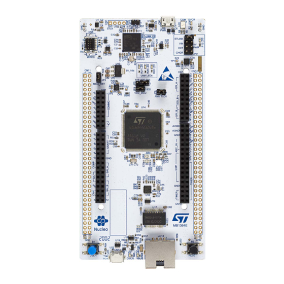
Figure 1. Nucleo-144 board (top view)
Pictures are not contractual.
June 2023
STM32H7 Nucleo-144 boards (MB1364)
®
Uno V3 connectivity, and the ST morpho headers
Figure 2. Nucleo-144 board (bottom view)
UM2407 Rev 3
UM2407
User manual
www.st.com
1/49
1
Advertisement
Table of Contents

Related Manuals for STMicroelectronics STM32H7


Summary of Contents for STMicroelectronics STM32H7
-
Page 1: Figure 1. Nucleo-144 Board (Top View)
Uno V3 connectivity, and the ST morpho headers provide an easy means of expanding the functionality of the Nucleo open development platform with a wide choice of specialized shields. The STM32H7 Nucleo-144 boards do not require any separate probe as they integrate the STLINK-V3E debugger/programmer. The STM32H7 Nucleo-144 boards come with comprehensive free software libraries and examples available with the STM32Cube MCU Package. -
Page 2: Table Of Contents
STM32H7 ........ - Page 3 UM2407 Contents 6.6.1 LEDs ........... 25 6.6.2 Push-buttons .
- Page 4 List of tables UM2407 List of tables Table 1. Ordering information ............7 Table 2.
- Page 5 USB composite device ........... . 17 Figure 9. Connecting an external debug tool to program the on-board STM32H7 ....18 Figure 10.
-
Page 6: Features
Features UM2407 Features The STM32H7 Nucleo-144 boards offer the following features: ®(a) ® • STM32H7 Arm Cortex core-based microcontroller in an LQFP144 package • Ethernet compliant with IEEE-802.3-2002 (depending on STM32H7 support) • USB OTG full-speed • 3 user LEDs •... -
Page 7: Ordering Information
MCU series in STM32 32-bit Arm Cortex STM32H7 series MCUs MCU product line in the series STM32H743 STM32 package pin count 144 pins STM32H7 flash memory size: -G for 1 Mbyte 2 Mbytes -I for 2 Mbytes Board version: void or 2 STLINK-V3E UM2407 Rev 3... -
Page 8: Development Environment
• Keil - MDK-ARM • STMicroelectronics - STM32CubeIDE Demonstration software The demonstration software, included in the STM32Cube MCU Package corresponding to the on-board microcontroller, is preloaded in the STM32 flash memory for easy demonstration of the device peripherals in standalone mode. The latest versions of the demonstration source code and associated documentation can be downloaded from www.st.com. -
Page 9: Conventions
Capacitor Cx ON Capacitor soldered Capacitor Cx OFF Capacitor not soldered In this document, for any information that is common to all sales types, the references are noted as the STM32H7 Nucleo-144 board and STM32H7 Nucleo-144 boards. UM2407 Rev 3 9/49... -
Page 10: Quick Start
Nucleo USB driver available on the www.st.com/stm32nucleo website. Power the board by connecting the STM32H7 Nucleo-144 board to a PC with a USB Type-A to Micro-B cable through the USB connector (CN1) on the ST-LINK. As a result, the PWR green LED (LD5) and COM LED (LD4) light up and the red LED (LD3) blinks. -
Page 11: Hardware Layout And Configuration
UM2407 Hardware layout and configuration Hardware layout and configuration The STM32H7 Nucleo-144 board is designed around the STM32H7 series microcontrollers in a 144-pin LQFP package. Figure 3 shows the connections between the STM32H7 and its peripherals (STLINK-V3E, push-buttons, LEDs, USB, Ethernet, ST Zio connectors, and ST morpho headers). -
Page 12: Nucleo-144 Board Layout
Hardware layout and configuration UM2407 Nucleo-144 board layout Figure 4. Nucleo-144 board top layout ST-LINK micro USB connector (CN1) ST-LINK RST (JP1) COM LED (LD4) DFU connector (CN2) (red/green) ST-LINK overcurrent LED (LD6) (red) Power LED (LD5) MIPI connector (CN5) (green) Power source selection (JP2) User LEDs (LD1-LD3) -
Page 13: Figure 5. Nucleo-144 Bottom Layout
UM2407 Hardware layout and configuration Figure 5. Nucleo-144 bottom layout IOREF Power selection (SB10, SB11, and SB20) MSv51398V3 UM2407 Rev 3 13/49... -
Page 14: Mechanical Drawing
Hardware layout and configuration UM2407 Mechanical drawing Figure 6. Nucleo-144 board mechanical drawing in millimeters 14/49 UM2407 Rev 3... -
Page 15: Figure 7. Nucleo-144 Board Mechanical Drawing In Mils
UM2407 Hardware layout and configuration Figure 7. Nucleo-144 board mechanical drawing in mils UM2407 Rev 3 15/49... -
Page 16: Embedded Stlink-V3E
In case the STM32H7 Nucleo-144 board is connected to the PC before installing the driver, the PC device manager might report some Nucleo interfaces as Unknown. To recover from this situation, after installing the dedicated driver, the association of Unknown USB devices found on the STM32H7 Nucleo-144 board to this dedicated driver must be updated in the device manager manually. -
Page 17: Stlink-V3E Firmware Upgrade
(for example new functionalities, bug fixes, and support for new microcontroller families), ST recommends keeping the STLINK-V3E firmware up to date before starting to use the STM32H7 Nucleo-144 board. The latest version of this firmware is available from the www.st.com website. -
Page 18: Table 5. Mipi-10 Debug Connector (Cn5)
Hardware layout and configuration UM2407 Figure 9. Connecting an external debug tool to program the on-board STM32H7 STLINK-V3E USB connector Power supply selection STLK_RST (JP1) External debug tool MSv61202V3 Table 5. MIPI-10 debug connector (CN5) MIPI-10 STDC14 Designation Reserved Reserved... -
Page 19: Power Supply
Power supply input from STLINK-V3E USB connector (default setting) The 5 V signal on the STLINK-V3E USB connector (CN1) can power the STM32H7 Nucleo- 144 board and its shield. Use the JP2 [1-2] configuration of the STLINK jumper (refer to Figure 10). -
Page 20: External Power Supply Input From Vin (7 To 12 V, 800 Ma Max)
, or +3.3 V. 6.4.2 External power supply input from VIN (7 to 12 V, 800 mA max) When the STM32H7 Nucleo-144 board is power supplied by VIN (refer to Table 6 Figure 11), the jumper (JP2) configuration must be [3-4] VIN. -
Page 21: External Power Supply Input 5V_Ext (5 V, 500 Ma Max)
6.4.3 External power supply input 5V_EXT (5 V, 500 mA max) When the STM32H7 Nucleo-144 board is power supplied by EXT (refer to Table 7 Figure 12), the jumper configuration must be the following: JP2 jumper on pin 5-6 ‘EXT’... -
Page 22: External Power Supply Input From A Usb Charger (5 V)
5V_EXT MSv61205V2 6.4.4 External power supply input from a USB charger (5 V) When the STM32H7 Nucleo-144 board is power supplied by a USB charger on CN1 (refer Table 8 Table 13), the jumper configuration must be JP2 [7-8] CHGR. -
Page 23: Debugging While Using Vin Or Ext As An External Power Supply
UM2407 Hardware layout and configuration Table 9. External power sources: 3V3_EXT (3.3 V) Input power name Connector pins Voltage range Max current CN8 pin 7 3 V to 3.6 V 1.3 A CN11 pin 16 Figure 14. Power supply input from 3V3_EXT (3.3 V) NO DEBUG MSv61203V1 MSv61207V2... -
Page 24: Clock Sources
• HSE on-board oscillator from X3 crystal (not provided): For its typical frequencies, capacitors, and resistors, refer to the STM32H7 series microcontroller datasheet and the application note Oscillator design guide for STM8AF/AL/S and STM32 microcontrollers (AN2867) for the oscillator design guide. The X3 crystal has the following characteristics: 25 MHz, 6 pF, 20 ppm. -
Page 25: Lse Clock (Low-Speed External Clock) - 32.768 Khz
6.6.1 LEDs User LD1: A green user LED is connected to the STM32H7 I/O PB0 (SB39 ON and SB47 OFF) or PA5 (SB47 ON and SB39 OFF) corresponding to the ST Zio D13. User LD2: A yellow user LED is connected to PE1. -
Page 26: Push-Buttons
• JP4 must be ON when STM32H7 is powered with 3V3_VDD (default) • If JP4 is OFF, an ammeter must be connected to measure the STM32H7 current. If there is no ammeter, the STM32H7 is not powered. Warning: On MB1364 REV.C, ‘VDD_MCU’ is also supplying Ethernet PHY (U15) and debug voltage translation (U1 and U10). -
Page 27: Usb Otg_Fs
STM32H7 I/Os. A green LED (LD8) lights in one of these cases: • Power switch (U12) is ON and the STM32H7 Nucleo-144 board works as a USB Host • is powered by another USB Host when the STM32H7 Nucleo-144 board works as a USB Device. -
Page 28: Ethernet
USB FS OVCR SB76 ON SB76 OFF ESD protection part is implemented on the USB port because all USB pins on STM32H7 are dedicated to USB port protection only on the STM32H7 Nucleo-144 board. USB pin ID is not used. -
Page 29: Solder Bridges And Jumpers
No incidence on ST-LINK STM32F723IEK6 NRST signal. JP1 (ST-LINK_RST) ST-LINK STM32F723IEK6 signal is connected to GND (ST-LINK reset to reduce power consumption). SWO signal of the STM32H7 (PB3) is connected to the ST- LINK SWO input. SB32 (SB26 must be OFF) (SWO) SWO signal of STM32H7 is not connected. - Page 30 PF0/PH0 is not connected to the ST morpho connector (CN11). ON, OFF PF1/PH1 is connected to the ST morpho connector (MCO is used as the main clock for STM32H7 on PF0/PH0– SB44 (PF1/PH1) SB45 ON). SB46 (PF0/PH0) PF0/PH0 and PF1/PH1 are not connected to the ST morpho...
- Page 31 NRST of STM32H7 is connected to Ethernet PHY (U15). SB74 (Ethernet nRST) RMII signal NRST of STM32H7 is not connected to Ethernet PHY (U15). USB overcurrent alarm is connected. SB76 (PG7) USB overcurrent alarm is not connected. PG7 is used as GPIO on the ST morpho connector (CN12).
- Page 32 Hardware layout and configuration UM2407 Table 14. Solder bridge and jumper configuration (continued) Bridge State Description ON, OFF PE6 is connected to SAI_A_SD (D59 of CN9) SB71, SB73 (PE6) OFF, ON PE6 is connected to TIMER_A_BKIN2 (D38 of CN10) PE2 is connected to SAI_A_MCLK (D56 of CN9). QSPI_BK1_IO2 cannot be used (D31 of CN10).
- Page 33 UM2407 Hardware layout and configuration All the other solder bridges present on the STM32H7 Nucleo-144 board are used to configure several I/Os and power supply pins for compatibility of features and pinout with the supported target STM32H7. The STM32H7 Nucleo-144 board is delivered with the solder bridges configured, according to the supported target STM32H7.
-
Page 34: Board Connectors
Board connectors UM2407 Board connectors Several connectors are implemented on the STM32H7 Nucleo-144 board. STLINK-V3E USB Micro-B connector (CN1) The USB Micro-B connector (CN1) is used to connect embedded STLINK-V3E to the PC for programming and debugging purposes. The related pinout for the USB STLINK-V3E connector is listed in Table Table 15. -
Page 35: Ethernet Rj45 Connector (Cn14)
UM2407 Board connectors Ethernet RJ45 connector (CN14) The STM32H7 Nucleo-144 board supports 10Mbps/100Mbps Ethernet communication with the PHY (U15) and integrated RJ45 connector (CN14). The Ethernet PHY is connected to the MCU via the RMII interface. The X4 oscillator generates the 25 MHz clock for the PHY. The 50 MHz clock for the MCU (derived from the 25 MHz crystal oscillator) is provided by the RMII_REF_CLK of the PHY. -
Page 36: Extension Connectors
® the bottom side. They include support for ARDUINO Uno V3. Most shields designed for ® ARDUINO Uno V3 can fit the STM32H7 Nucleo-144 board. ® To cope with ARDUINO Uno V3, apply the following modifications: • SB55 and SB62 must be ON •... - Page 37 UM2407 Extension connectors Caution:1 The I/Os of the STM32H7 series microcontroller are 3.3 V compatible instead of 5 V for ® ARDUINO Uno V3. ® Caution:2 R37 must be OFF before implementing the ARDUINO shield with V power provided REF+ on CN7 pin 6.
-
Page 38: Table 18. Zio Connector (Cn7) Pinout
NUCLEO-H723ZG, NUCLEO-H743ZI2, and NUCLEO-H753ZI pin assignments Table 18. ZIO connector (CN7) pinout STM32H7 Signal name MCU function Pin name Signal name STM32H7 pin MCU function name I2S_A_MCK I2S_2 I2C_A_SCL I2C_1_SCL I2S_A_SD PB15 I2S_2 I2C_A_SDA I2C_1_SDA I2S_A_CK PB13 I2S_2 VREFP VREFP... -
Page 39: Table 20. Zio Connector (Cn9) Pinout
Table 19. ZIO connector (CN8) pinout (continued) STM32H7 STM32H7 Pin name Signal name MCU function Pin name Signal name MCU function 3.3 V input/output SDMMC_D3 PC11 SDMMC 5 V output SDMMC_CK PC12 SDMMC ground SDMMC_CMD SDMMC ground Power input Table 20. ZIO connector (CN9) pinout... -
Page 40: Table 21. Zio Connector (Cn10) Pinout
Table 20. ZIO connector (CN9) pinout (continued) STM32H7 STM32H7 Pin name Signal name MCU function Pin name Signal name MCU function CAN_TX CAN_1 SAI_B_FS SAI_1_B 1. PE2 is connected to both CN9 pin 14 (SAI_A_MCLK) and CN10 pin 25 (QSPI_BK1_IO2). Only one function must be used at one time. -
Page 41: St Morpho Connector
STM32H7 Nucleo- 144 board. All signals and power pins of the STM32H7 are available on the ST morpho connector. An oscilloscope, logical analyzer, or voltmeter can also probe this connector. - Page 42 Extension connectors UM2407 Table 22. Pin assignment of the ST morpho connector (continued) CN11 odd pins CN11 even pins CN12 odd pins CN12 even pins Pin nbr Pin name Pin nbr Pin name Pin nbr Pin name Pin nbr Pin name PE13 PE11 PF13...
-
Page 43: Nucleo-144 Boards (Mb1364) Information
UM2407 Nucleo-144 boards (MB1364) information Nucleo-144 boards (MB1364) information Product marking The stickers located on the top or bottom side of all PCBs provide product information: • First sticker: product order code and product identification, generally placed on the main board featuring the target device. Example: Product order code Product identification... -
Page 44: Nucleo-144 Boards (Mb1364) Product History
Nucleo-144 boards (MB1364) information UM2407 Nucleo-144 boards (MB1364) product history Table 23. Product history Order Product Product change Product details Product limitations code identification description MCU: – STM32H743ZIT6 The IDD measurement of revision ‘V’ the STM32H7x3 MCU cannot be performed in MCU errata sheet: Standby mode because of NUH743ZI$AT1... -
Page 45: Board Revision History
UM2407 Nucleo-144 boards (MB1364) information Table 23. Product history (continued) Order Product Product change Product details Product limitations code identification description MCU: – STM32H723ZGT6 revision ‘Z’ MCU errata sheet: NUH723ZG$AT1 Initial revision No limitation – STM32H72xx/73xx device errata (ES0491) Board: –... -
Page 46: Federal Communications Commission (Fcc) And Ised Canada Compliance Statements
Part 15.21 Any changes or modifications to this equipment not expressly approved by STMicroelectronics may cause harmful interference and void the user's authority to operate this equipment. Part 15.105 This equipment has been tested and found to comply with the limits for a Class B digital device, pursuant to part 15 of the FCC Rules. -
Page 47: Ised Compliance Statement
UM2407 Federal Communications Commission (FCC) and ISED Canada Compliance Statements 10.2 ISED Compliance Statement Compliance Statement ISED Canada ICES-003 Compliance Label: CAN ICES-3 (B) / NMB-3 (B). Déclaration de conformité Étiquette de conformité à la NMB-003 d'ISDE Canada: CAN ICES-3 (B) / NMB-3 (B). UM2407 Rev 3 47/49... -
Page 48: Revision History
Revision history UM2407 Revision history Table 25. Document revision history Date Revision Changes 14-Mar-2019 Initial version Added: – NUCLEO-H723ZG board – Section 9 with Board revision history Known limitations 11-Jun-2020 Updated: – Section 6.3 switch to STLINK-V3E – Figure 1 Figure 5, and Figure 9... - Page 49 IMPORTANT NOTICE – READ CAREFULLY STMicroelectronics NV and its subsidiaries (“ST”) reserve the right to make changes, corrections, enhancements, modifications, and improvements to ST products and/or to this document at any time without notice. Purchasers should obtain the latest relevant information on ST products before placing orders.
Need help?
Do you have a question about the STM32H7 and is the answer not in the manual?
Questions and answers