Table of Contents
Advertisement
Advertisement
Table of Contents

Related Manuals for GE ASTAT XT QT 0008U Series


Summary of Contents for GE ASTAT XT QT 0008U Series
- Page 1 GE Consumer & Industrial ASTAT XT User Manual...
- Page 2 2. Make sure that this manual is delivered to the end user. 3. The policy of GE Industrial Systems is one of continuous improvement. The right is reserved to alter the design on any structural details of the products at any time without giving notice.
-
Page 3: Table Of Contents
• Table of Contents ASTAT-XT User Manual Generalities..............................7 1.1 Squirrel-Cage Motor Starting..............................7 1.2 Advantages of the ASTAT-XT Solid State Soft Starters....................7 Types and Ratings ............................8 2.1 IEC Ratings. Recommended Motor and Type Unit Ratings..................8 2.2 NEMA Ratings . Recommended Motor and Type Unit Ratings................. 9 2.3 Thermal Characteristics ................................10 Technical Specifications ..........................11 3.1 General Specifications ................................11... - Page 4 D.Set: Generator Parameters Wiring..........................71 8.17 8.18 Short Circuit Protection................................72 8.18.1 Type 1 Coordination ..............................72 8.18.1.1 Type 1 Coordination with GE Circuit Breakers: ..................72 8.18.1.2 Type 1 Coordination with Type aM Siba Fuses:...................72 8.18.2 Type 2 Coordination ..............................72 8.19 Transient Protection ................................73 Inside Delta Configuration..............................74...
- Page 5 • Table of Contents 8.20.4 ASTAT-XT Connected Inside Delta w/Bypass Contactor and Inside Delta Contactor ....76 8.20.5 ASTAT-XT Connected Inside Delta - Reverse Speed..................77 Dimensions..............................78 9.1 UL cUL Approved Models................................78 9.2 Non UL cUL Approved Models..............................82 Appendix A - MODBUS RTU Protocol........................86 A.1.
- Page 6 • Table of Contents C.6.1. Class Attributes (Instance 0)..........................113 C.6.2. Instance Attributes (Instances 1-2) Explicit, Polled I/O................113 C.6.3. Common Services ..............................115 C.7. Softstart Object (2D 1 Instance)...........................115 HEX - C.7.1. Class Attributes (Instance 0)..........................115 C.7.2. Instance Attributes (Instance 1) ......................... 115 C.7.2.1.
-
Page 7: Generalities
• Generalities GENERALITIES Squirrel-Cage Motor Starting There are numerous applications where soft starting and limited current peak are needed, thereby making direct starting of squirrel-cage motors impossible. Traditionally in such cases other types of starting with reduced stator voltage have been resorted to. The best-known are star-delta starters, autotransformer starters, stator resistance starters or using part winding motors. -
Page 8: Types And Ratings
• Types and Ratings TYPES AND RATINGS IEC Ratings . Recommended Motor and Type Unit Ratings. Light Normal Duty (IEC Class 10) Heavy Duty (IEC Class 20) Type Unit Duty Recommended Motor Ratings Recommended Motor Ratings Current 230V 400V 480V 575V 690V Current... -
Page 9: Nema Ratings . Recommended Motor And Type Unit Ratings
• Types and Ratings NEMA Ratings . Recommended Motor and Type Unit Ratings. Light Duty Normal Duty Heavy Duty Type Unit Nema 10 Nema 20 Nema 30 Current 230V 460V 575V Current 230V 460V 575V Current 230V 460V 575V rating rating rating QTx0008Uxxxx... -
Page 10: Thermal Characteristics
• Types and Ratings Thermal Characteristics The ASTAT-XT allows the user to select motor protection according IEC Class 10, 20 and NEMA 10, 20 or 30, selectable by Overload Class parameter (refer to section 4.7.2 page 27) -
Page 11: Technical Specifications
• Technical Specifications TECHNICAL SPECIFICATIONS General Specifications General Information: Supply Voltage: Line to line 230-690V (to be specified) + 10%-15% Frequency: 45 – 65 Hz (fixed or variable frequency source) Control Supply: Either 110VAC or 230VAC (to be specified) +10% - 15% Control Inputs: Either 90-230VAC or 24VDC (to be specified) Load:... - Page 12 • Technical Specifications Phase Loss, Under/over Trips when one or two phases are missing, or frequency is < 40Hz or > 65Hz. Frequency: Optional auto reset. Phase Sequence: Trips when phase sequence is wrong Long Slow Speed Time: Trips if operating at slow speed TRQ for more than 1-30 sec (1-250 sec Wrong Connection: Prevents starting, trips if motor is not connected / incorrectly connected to the ASTAT-XT (not active in D.Set: Generator Parameters)
-
Page 13: Weight
• Technical Specifications Weight Model Weight QTx0008Uxxxx QTx0017Uxxxx QTx0031Uxxxx 11.7 QTx0044Uxxxx 14.8 QTx0058Uxxxx 14.8 QTx0072Uxxxx 14.8 QTx0085Uxxxx 15.2 33.5 QTx0105Uxxxx 15.2 33.5 QTx0145Uxxxx 15.2 33.5 QTx0170Uxxxx 15.2 33.5 QTx0210Nxxxx 32.7 72.1 QTx0210Uxxxx 46.5 102.5 QTx0310Nxxxx 32.7 72.1 QTx0310Uxxxx 46.5 102.5 QTx0390Nxxxx 32.7 72.1... - Page 14 • Technical Specifications Terminal Function Description Terminal F Fan control An internal jumper, connected between the fan and terminal 2 enables three modes of operation (refer to section 5.6 page 51). For fan power consumption, see technical specification in section 3 page 11. Terminal 4 Input –...
- Page 15 • Technical Specifications Terminal Function Description Terminal 15 Programmable Fault Output When the At Fault Close function is selected, the relay relay (Common) is energized upon fault. The contact returns to its original position when one of the following occurs: •...
- Page 16 • Technical Specifications Terminal Function Description Terminal SG No connection • Standard RS485, half duplex with Modbus protocol, baud rate 1200, 2400, 4800, 9600 BPS. Terminal D- RS-485 communication (-) Twisted shielded pair should be used. • Connect shield to ground on the PLC/Computer side. Terminal D+ RS-485 communication (+) •...
-
Page 17: I/O Wiring
• Technical Specifications I/O Wiring... -
Page 18: Ordering Information
• Technical Specifications Ordering Information Notes: cUL Certification (*1) – ASTAT-XT up to 600V, and up to 170A (Cat Numbers up to to QT10170_ or QT20170) are always cUL certified. Option “N” not available - Units QT1 or QT2 from QTx0950_ up to QTxx1400 are not UL certified. Option “U” not available. - Units QT3x, rated to 690V, are not UL certified. -
Page 19: Operating Modes
• Technical Specifications Operating Modes Operating Mode Description Starting Voltage 5 to 80% Un. Adjustable via Starting Voltage parameter. Fixed level of 80% Un with an adjustable time, 0-1 sec., via Kickstart Kick Start Time parameter. 1-30 sec. (1-90 sec.). Adjustable via Ramp UP Time. sec.). -
Page 20: Control Keypad
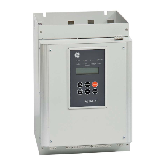
• Control Keypad CONTROL KEYPAD The control keypad is the interface between the ASTAT-XT and the user. The ASTAT-XT control keypad features: Eight indication LEDs (On, Start, Run, Soft Stop, Stop, Save/Slow Speed, Dual Set/Reverse, Fault) Two lines of 16 alphanumeric characters each with selectable languages – English, Italian, German, and Spanish. Six push-buttons - Mode, Reset, Select, Set, Up (▲) and Down (▼) keys. -
Page 21: Push-Buttons
• Control Keypad Push-Buttons Scrolls through the display and programming menus of the ASTAT-XT. Mode When a mode name is displayed, pressing this button drills down to the parameters for that mode. Select When a parameter is displayed, pressing this button scrolls to the next parameter. Allows the operator to increment adjusted values shown in the display. -
Page 22: Special Actions Performed In Test/Maintenance Mode
Press the Mode and ▼ keys simultaneously. The LCD will display: Test/Maintenance Statistics Press the Select key twice. The LCD will display: Firmware Version STRT.GE-031208 Press the Mode and ▼ keys simultaneously to exit the Test/Maintenance mode. The LCD will display: Motor Current Obtain Default Parameters 4.5.3 Press the Mode and ▼... -
Page 23: Calibrate Voltage And Current (Factory Use Only!)
• Control Keypad Press the Mode and go back to: Motor Current Calibrate Voltage and Current (Factory Use Only!) 4.5.5 Press the Mode and ▼ keys simultaneously. The LCD will display: Test/Maintenance Statistics Press the Select key five times. The LCD will display: Calibration VOLT 0 VOLT Press the Select key. -
Page 24: Overview Of All Mode Pages And Factory Defaults
• Control Keypad Overview of All Mode Pages and Factory Defaults Appears only in Maximized Display Page Main Settings Start Settings Stop Settings DUAL Settings - **** - - **** - Parameters - **** Function & Default Function & Default Function &... - Page 25 ***Statistics*** PROFI. Network ID Display and default values Auto Test S. Link Par. Set Press UP Key Disabled Firmware Version Ser. Link Control STRT-GE-270508 Disabled Store Settings Default Data Store Settings Reset Statistics COMM. Parameters COMM. Protocol Calibration VOLT DeviceNet...
-
Page 26: Display Mode
• Control Keypad Display Mode – Page 0 4.7.1 Function & Unit Description Default Displays operating current of the motor. Motor Current ASTAT-XT’s Default Display. After pressing the Mode or Select keys, a time delay is initiated. Following the delay the LCD returns to display Motor Current. -
Page 27: Main Settings
• Control Keypad Main Settings – Page 1 4.7.2 Function & Range Unit Description Default 8 – 1400 Sets ASTAT-XT’s Rated Current (Type Unit) Starter Current Check the name plate on the soft starter and make sure that 58 Amp. digits 4 to 7 of the model name are the same as the Starter Current setting. - Page 28 • Control Keypad Function & Range Unit Description Default IEC CLASS 10; Sets Overload CLASS. Overload Class IEC CLASS 20; Overload Class is operational as programmed in the IEC CLASS 10 NEMA CLASS Overload Protect parameter. (see next parameter) The O/L circuitry incorporates a thermal memory register NEMA CLASS that calculates heating minus dissipation of the motor.
-
Page 29: Start Settings
• Control Keypad Start Settings – Page 2 4.7.3 Function & Range Unit Description Default Sets ASTAT-XT’s Soft Start Curve. Soft Start Curve (Standard) Refer to section 4.7.3.1 on page 32. 0(Standard) 1 !! 2 !! 3 !! 4 (Torque) 0 –1.0 sec. - Page 30 • Control Keypad Function & Range Unit Description Default 10-50% % of Sets the motor’s Starting Voltage. Starting Voltage After mains The motor’s torque is directly proportional to the square of the 30 % reaching voltage voltage. 50% the This adjustment also determines the inrush current and display mechanical shock.
- Page 31 • Control Keypad Function & Range Unit Description Default 100-700% % of Sets the motor’s highest current during starting. Current Limit Motor A setting that is too high will increase the current drawn from 400% of Im Current mains and speed up acceleration. A setting that is too low may prevent the motor from completing the acceleration process and reaching full speed.
-
Page 32: Soft Start Parameters
• Control Keypad Function & Range Unit Description Default 1-60 sec. Sets Maximum Start Time Max. Start Time The maximum allowable start time, from the start signal to the 30 SEC. end of the acceleration process. If voltage/speed does not reach nominal during Max. - Page 33 • Control Keypad Soft Start Curves 1-3 - Pump Control - Induction motors produce peak torque of up to 3 times the rated torque towards the end of starting process. In some pump applications, this peak may cause a pressure surge in the pipes.
-
Page 34: Stop Settings
• Control Keypad Stop Settings – Page 3 4.7.4 Function & Range Unit Description Default Sets ASTAT-XT’s Soft Stop Curve. 0 (Standard) Soft Stop Curve 1 !! Refer to section 4.7.4.1 on page 34. 0(Standard) 2 !! 3 !! 4 (Torque) 1–30 Sec. -
Page 35: Soft Stop Parameters
• Control Keypad Soft Stop Parameters 4.7.4.1 The ASTAT-XT incorporates 5 stopping curves that enable you to select the suitable torque curve Soft Stop Curve 0 – Standard Curve (Default) – voltage is linearly reduced from nominal to zero. The most stable and suitable curve for preventing prolonged stopping and motor overheating. Soft Stop Curves 1, 2, 3 Pump Control –... -
Page 36: Dual Settings Parameters
• Control Keypad DUAL Settings Parameters – Page 4 4.7.5 When D.Set: Generator Parameters is required, do the following: Program PROG. Input #8 to DUAL Settings (this is its default setting). Refer to section 4.7.8 on page 40. Set dip switch #3 to ON (refer to section 5.5.3 on page 50). Connect control inputs voltage to input terminal 8. -
Page 37: Slow Speed & Energy Save Parameters
• Control Keypad Slow Speed & Energy Save Parameters – page 5 4.7.6 Function & Range Unit Description Default 0(MIN.) – Sets the required energy saving level. Energy Saving 10(MAX.) Activated when the motor has a light load for extended 0 (MIN) periods of time. -
Page 38: Fault Settings
• Control Keypad Fault Settings – Page 6 4.7.7 Function & Range Unit Description Default Enabled Sets Phase Loss trip Phase Loss Phase Loss protection trips the ASTAT-XT when 1 or 2 phases Enabled are missing. Notes: If ASTAT-XT trips on Phase Loss do the following: In cases where the current transformers are connected externally (ASTAT-XT 950-1400A models), verify that that the current transformers are not grounded. - Page 39 • Control Keypad Function & Range Unit Description Default PTC/NTC Sets input Thermistor Type Thermistor Type Measures the motor’s thermistor resistance and trips the ASTAT-XT when the level decreases below set level. Disabled, Sets ASTAT-XT’s Thermistor Trip mode of operation. Thermistor Trip 0.1–10Kohm Note:...
-
Page 40: I/O Settings Parameters
• Control Keypad I/O Settings Parameters – Page 7 4.7.8 Function & Range Unit Description Default Reset; Sets the terminal 7 function PROG. Input # 7 Slow Speed; Refer to section 4.7.8.1 on page 41. Reset Energy Saving Dual Settings; Sets the terminal 8 function PROG. -
Page 41: Terminal 7 And 8 Programming
• Control Keypad Terminal 7 and 8 Programming 4.7.8.1 Input Terminal 7 Description Programmed Function Reset (default setting) Input terminal 7 is used as Reset to reset all ASTAT-XT faults. The Reset command will take effect only if the start command is removed. (Except for Undercurrent RST when enabled. -
Page 42: Comm. Parameters - Page 8 - With The Modbus Standard Pcb
• Control Keypad COMM. Parameters – Page 8 – With the Modbus standard PCB 4.7.9 Function & Range Unit Description Default Profibus/ Sets ASTAT-XT’s communication PROTOCOL. COMM.Protocol Modbus/ Operational when the Modbus communication PCB is installed. Modbus DeviceNet 1200, Sets ASTAT-XT’s Baud Rate. Baud Rate 2400, 9600 (MODBUS) -
Page 43: Comm. Parameters - Page 8 - With The Devicenet Optional Pcb
• Control Keypad Comm. Parameters – Page 8 – With the DeviceNet Optional PCB 4.7.11 Function & Range Unit Description Default Profibus/ Sets ASTAT-XT’s communication protocol. COMM. PROTOCOL Modbus/ Operational when the optional communication PCB is DeviceNet DeviceNet installed. Set the Baud Rate by changing the position of the Baud Rate rotary switches on the optional PCB as shown on section Set Manually... -
Page 44: Statistical Data
• Control Keypad Statistical Data – page 9 4.7.12 Function & Range Unit Description Default Sec. Displays the last starting time in seconds. Last Start Time Starting time is the duration until motor current No Data drops to nominal. Displays the last starting current. Last Start Curr. -
Page 45: Non Adjustable Protection And Fault Reset
• Control Keypad Non Adjustable Protection and Fault Reset Under/Over Frequency 4.8.1 Operational when the ASTAT-XT is energized and protects the motor when the frequency is less than 45 or greater than 65Hz. Phase Loss 4.8.2 Operational when the ASTAT-XT is energized, provided this protection has not been de-activated. Phase loss protection trips the ASTAT-XT when 1 or 2 phases are missing. -
Page 46: Auto Reset
• Control Keypad Auto Reset 4.8.9 Undervoltage and Phase Loss faults can auto-reset (refer to section 4.7.7 on page 38). The ASTAT-XT will reset itself 60 seconds after voltage was fully restored, provided that the START signal is removed. Undercurrent fault can be set to auto-reset (refer to section 4.7.7 on page 38). The ASTAT-XT will reset itself when a programmed time delay has elapsed, even if the START signal is not removed. -
Page 47: Installation
• Installation INSTALLATION WARNINGS Do not interchange line and load connections When mains voltage is connected to the ASTAT-XT, even if control voltage is disconnected, full voltage may appear on the ASTAT-XT’s load terminals. Therefore if isolation is required you must connect an isolation device between the mains and the ASTAT-XT. -
Page 48: Forced Ventilation
• Installation While a 820A motor is running and the motor current is 820A, heat dissipation can be calculated as: Ploss=3x1.3x820+150=3,198Watt≈3.2kW When a bypass contactor is used this changes the previous calculation to: Ploss=3x1.3x0+150=150Watt≈0.15kW It is obvious that using a bypass contactor can significantly reduce energy consumption. You can reduce the amount of heat in an internal enclosure by using a bypass contactor and/or using additional ventilation. -
Page 49: Dip Switch Settings On The Main Pcb
• Installation ASTAT-XT main PCB. Dip switches location, software version label location and PCB hardware version identification. Dip Switch Settings on the Main PCB The dip switch has eight separate switches. It is located under the front cover of the control module (models QTx0085x-QTx1400) or under the display unit (models QTx0008x-QTx0072). -
Page 50: Switch # 2 - Not Used
• Installation Switch # 2 – Not used 5.5.2 Switch # 3 – Main/ D.Set: Generator Parameters 5.5.3 Refer to section 8.17 page 71 for information regarding the operation of this switch. WARNING When operating in D.Set: Generator Parameters, the motor must be loaded to avoid vibration during starting and stopping. -
Page 51: Internal Fan Control
• Installation Internal Fan Control An internal jumper connected between the fan and terminal 2, enables three modes of operation. For fan power consumption, see technical specification section 3 page 11. Fan control jumper J1. Refer to section 5.4 page 48 for J1 location. Continuous mode (factory default) –... -
Page 52: Remote Key-Pad Installation
• Installation Switch No. 4-20 mA* 0-20 mA 0-10VDC S1 - Switch # 1 S1 - Switch # 2 S1 - Switch # 3 S1 - Switch # 4 S2 - Switch # 1 S2 - Switch #2 Not used Not used Not used * Factory default setting... -
Page 53: Starting Procedure
• Starting Procedure STARTING PROCEDURE Note: It is necessary to connect a motor to load terminals; otherwise Shorted SCR or WRONG CONNECTION faults are activated (OC or Wrong CON.). Other loads such as incandescent light bulbs, resistors, etc. may also cause an OC or Wrong CON. -
Page 54: Standard Starting Procedure
• Starting Procedure Standard Starting Procedure Connect Control Supply voltage. On LED will light. Review all parameters with the Mode and Select keys. Set parameters as required. If necessary, return to Default Parameters (refer to section 4.5.3 page 63). Connect mains voltage to the line terminals of the ASTAT-XT. Set LCD to show Motor Current. -
Page 55: Examples Of Starting Curves
• Starting Procedure Continued from previous page Apply the START command If acceleration time is too short, increase Ramp Motor acceleration UP Time setting and/or decrease Current time to full speed is Limit setting (when decreasing Current as required? Limit, make sure that the motor increases speed gradually and does not stall). -
Page 56: Special Starting Using Dual Settings
• Starting Procedure Upon START the voltage and current increase until the current reaches the Current Limit value. The voltage remains at this value until the motor reaches close to nominal speed, where current starts to decrease and voltage continues to ramp-up to nominal. Special Starting Using DUAL Settings 6.2.3 Using two starting characteristics, the ASTAT-XT will accelerate using standard characteristics (Starting... -
Page 57: Special Starting - Using Dual Settings - Wiring Diagram
• Starting Procedure Special Starting – Using DUAL Settings – Wiring Diagram 6.2.3.1 Choosing a Suitable Pump Curve (Centrifugal Pumps) 6.2.4 Starting Curve 6.2.4.1 • Adjust Main Settings as necessary (Starter Current, Motor Current, etc.). Set Soft Starting Curve, Ramp UP Time, Current Limit, and Starting Voltage to their default •... -
Page 58: Stopping Curve
• Starting Procedure Stopping Curve 6.2.4.2 Adjust Main Parameters as necessary (Starter Current, Motor Current, etc.) • • Set Soft Stop Curve and Ramp DOWN Time to their default values (Curve 0 and 10 sec. respectively). • Stop the pump, watching the pressure gauge and check valve as the pump stops. Look for overshooting (“water hammer”) of the gauge (abruptly stops the pump and the motor). -
Page 59: Trouble Shooting
• Trouble Shooting TROUBLE SHOOTING Upon fault – motor stops, the Fault LED lights and Fault Relay chances position. The LCD shows TRIP: < fault description>. (for example: Trip: Undercurrent). Storage Error displays in case of a failure in parameter storing. Storage Error Wait 3 seconds and try to store again. - Page 60 • Trouble Shooting Trips the ASTAT-XT when line current drops below the preset level for the preset time. Undercurrent FLT Check Undercurrent FLT and Undercurrent DLY settings; check line currents of L1, L2, L3. For protection parameters settings refer to section 4.7.2 page 27. Trips the ASTAT-XT when line voltage drops below the preset level for the preset time.
- Page 61 • Trouble Shooting Trips the ASTAT-XT when one or more motor phases is not properly connected to Wrong Connection ASTAT-XT’s load terminals or if there is an internal disconnection in the motor winding. Verify that the motor is connected properly. See note 1 at the end of this section.
-
Page 62: Application Diagrams
• Application diagrams APPLICATION DIAGRAMS Terminal 21 Connections With Various Mains Mains Diagram Terminal 21 Connection 3P+N+GR - Connect terminal 21 to neutral 3P+N - Connect terminal 21 to neutral 3P+GR - Connect terminal 21 to ground 3P - Leave terminal 21 unconnected 3P - Leave terminal 21 unconnected 3P+GR - Leave terminal 21 unconnected WARNINGS... -
Page 63: Control Supply, Control Input And Mains Are From The Same Source, Neutral Connected To Terminal
• Application diagrams Control Supply, Control Input and Mains are From the Same Source, Neutral Connected to Terminal Notes: • Use this diagram when Control Supply, Control Input and mains are all from the same source, and terminal 21 is connected to neutral as per section 8.1 page 62. -
Page 64: Control Supply And Control Input From Separate Sources
• Application diagrams Control Supply and Control Input from Separate Sources Notes: • Use this diagram when Control Supply and Control Input voltages are not from the same source. • Connect terminal 21 as per section 8.1 page 62. • Supply must be protected for short circuit and over load. -
Page 65: Soft Start And Immediate Stop (No Soft Stop)
• Application diagrams Soft Start and Immediate Stop (no Soft Stop) Notes: When switch A closes the motor will • soft start. • When switch A opens the motor will stop immediately (no soft stop). • The drawing shows Control Supply and Control Input from the same source. -
Page 66: Energy Save, Slow Speed Or Reset
• Application diagrams 8.10 Energy Save, Slow Speed or Reset Notes: • Switch D can be used as an Energy Save/Slow Speed/ Reset, as programmed in I/O Programming Parameters. Refer to section 4.7.8 page 40. • Energy Save or Slow Speed functions require a maintained contact to operate. -
Page 67: External Fault
• Application diagrams 8.12 External Fault Note: Switch E can be used as an External Fault input only when terminal 21 is connected to neutral or ground. 8.13 Line Contactor Notes: • Typical wiring when ASTAT-XT is retrofitted into an existing system to reduce modifications in existing installations. -
Page 68: Bypass Contactor
• Application diagrams 8.14 Bypass Contactor Notes: • End of Ramp relay is energized after a programmed time delay EOR Relay Delay Refer to section 4.7.3 page 29 for programming. • The End of Ramp relay is de-energized when: o SOFT STOP or STOP signals are initiated o Energy Save signal is initiated o Slow Speed/ Slow Speed Reverse signal is initiated o Fault condition occurs... -
Page 69: Reversing With Two Line Contactors
• Application diagrams 8.15 Reversing with Two Line Contactors Notes: • A N.O. auxiliary contact in each of the two line contactors C1 & C2 controls the START/STOP command. Closure of either contactor will supply main power and a start signal to the ASTAT-XT. It is recommended to employ a mechanical interlock between the forward and reverse contactors. -
Page 70: Operating Via Communication Links
• Application diagrams 8.16 Operating via Communication Links Notes: • In order to operate via communication, either Modbus (standard) or Profibus (optional) or DeviceNet (optional) optional PCBs must be installed and wired properly. ASTAT-XT must be properly grounded. • • ASTAT-XT must be programmed to enable control (not only monitoring). -
Page 71: D.set: Generator Parameters Wiring
• Application diagrams 8.17 D.Set: Generator Parameters Wiring Notes: • When starting from a diesel generator make sure that its size is suitable. Based on experience, the power (kW) of a diesel generator should usually exceed at least 1.8 times the power (kW) of the motor in order to enable consistent motor starts, consult the factory if necessary. -
Page 72: Short Circuit Protection
8.18 Short Circuit Protection Type 1 Coordination 8.18.1 For Type 1 coordination either aM type fuses or Circuit breakers can be applied as shown in the tables below: 8.18.1.1 Type 1 Coordination with GE Circuit Breakers: Soft Starter GE Circuit Breaker Rated Current... -
Page 73: Transient Protection
• Application diagrams Soft Starter Bussman Fuses DIN 43620 Rated Current Rated Breaking Current Capacity P/No. Size Type 170M3808D H.S.D.I. 5000 170M3810D H.S.D.I. 10000 170M3813D H.S.D.I. 12000 170M3814D H.S.D.I. 15000 170M3814D H.S.D.I. 18000 170M3815D H.S.D.I. 50000 170M3816D H.S.D.I. 60000 170M3817D H.S.D.I. -
Page 74: Inside Delta Configuration
• Application diagrams 8.20 Inside Delta Configuration General Information 8.20.1 When the ASTAT-XT is installed Inside Delta, the individual phases of the ASTAT-XT are connected in series with the individual motor windings (6 conductor connections as with the star-delta starter). The ASTAT-XT must only conduct about 58 % (=1\√3) of the rated motor current. -
Page 75: Motor Connection And Terminals
• Application diagrams INSIDE DELTA Beware! WARNINGS Wrong connection of the ASTAT-XT or the motor may seriously damage the motor or the ASTAT-XT. When using Inside Delta connection: • It is highly recommended to use a line contactor in order to avoid possible damage of the motor if the SCR is short circuited in the ASTAT-XT. -
Page 76: Astat-Xt Connected Inside Delta W/Bypass Contactor And Inside Delta Contactor
• Application diagrams ASTAT-XT Connected Inside Delta w/Bypass Contactor and Inside Delta Contactor 8.20.4 ASTAT-XT connection Inside Delta with bypass contactor to the ASTAT-XT and Inside Delta contactor. C1 is a bypass contactor. C2 is an Inside Delta contactor. U1-U2, V1-V2, W1-W2 are motor windings. 1L1-2T1, 3L2-4T2, 5L3-6T3 are ASTAT-XT controlled phases. -
Page 77: Astat-Xt Connected Inside Delta - Reverse Speed
• Application diagrams ASTAT-XT Connected Inside Delta - Reverse Speed 8.20.5 IMPORTANT! If speed reversing is required, L1, L2 and L3 on the input of the ASTAT-XT can not be switched! This is because Phase Sequence Disabled can not be implemented when ASTAT-XT is connected Inside Delta. Thus, in order to reverse motor rotation two motor windings need to be switched as shown in the following diagram: (Winding V1-V2 is switched with winding U1-U2): Reverse speed with ASTAT-XT connection Inside Delta with bypass contactor to the ASTAT-XT... -
Page 78: Dimensions
• Dimensions DIMENSIONS UL cUL Approved Models ASTAT-XT 8A 17A 31A. Cat numbers QTx0008U_, QTx0017U_, QTx0031U_ Notes: • Mains voltage terminals: 16mm • Add 20 mm to the depth dimension when the optional remote key-pad is installed. ASTAT-XT 44A 58A. Cat numbers QTx0044U_, QTx0058U_ Notes: Mains voltage terminals ( 1L1, 3L2, 5L3) and preparation for bypass terminals (A, B, C): 16mm •... - Page 79 • Dimensions ASTAT-XT 72A. Cat number QTx0072U_ Notes: • Mains voltage terminals: 35mm Add 20 mm to the depth dimension when the optional remote key-pad is installed. • ASTAT-XT 85A 105A. Cat numbers QTx0085U_, QTx0105U_ Note: Add 20 mm to the depth dimension when the optional remote key-pad is installed.
- Page 80 • Dimensions ASTAT-XT 145A 170A. Cat numbers QTx0145U_, QTx0170U_ Note: Add 20 mm to the depth dimension when the optional remote key-pad is installed. ASTAT-XT 210A 310A 390A. Cat numbers QTx0210U_, QTx0310U_, QTx0390U_ Notes: For the dimensions of non UL cUL approved models QTx0210N_, QTx0310N_, QTx0390N_, refer to section •...
- Page 81 • Dimensions ASTAT-XT 460A. Cat number QTx0460U_ Notes: • For the dimensions of non UL cUL approved model QTx0460N_ refer to section 9.2 page 82. • Add 20 mm to the depth dimension when the optional remote key-pad is installed. ASTAT-XT 580A 820A.
-
Page 82: Non Ul Cul Approved Models
• Dimensions Non UL cUL Approved Models ASTAT-XT 210A 310A 390A. Cat numbers QTx0210N_, QTx0310N_, QTx0390N_ Notes: • For the dimensions of UL cUL approved models QTx0210U_, QTx0310U_, QTx0390U_ refer to section 9.1 page 78. • Add 20 mm to the depth dimension when the optional remote key-pad is installed. ASTAT-XT 460A. - Page 83 • Dimensions ASTAT-XT 580A. Cat number QTx0580N_ Notes: • For the dimensions of UL cUL approved model QTx0580U_ refer to section 9.1 page 78. • Add 20 mm to the depth dimension when the optional remote key-pad is installed. ASTAT-XT 650A. Cat number QTx0650N_ Note: Add 20 mm to the depth dimension when the optional remote key-pad is installed.
- Page 84 • Dimensions ASTAT-XT 950A. Cat number QTx0950N_ Notes: Must be operated with a bypass contactor • • Add space for current transformers (supplied separately from the main unit) and bus bars for preparation for bypass • Approximate current transformer dimensions: W=240mm, H=130mm, D=90mm •...
- Page 85 • Dimensions ASTAT-XT 1100A 1400A. Cat numbers QTx1100N_, QTx1400N_ Notes: • Must be operated with a bypass contactor • Add space for current transformers (Supplied separately from main unit) and bus bars for preparation for bypass Approximate current transformer dimensions: •...
-
Page 86: Appendix A - Modbus Rtu Protocol
• Appendix A - MODBUS RTU Protocol APPENDIX A - MODBUS RTU PROTOCOL A.1. Introduction This document summarizes the serial link protocol to / from the DIGITAL SOFT STARTER(ASTAT-XT). Features: • RS485 Hardware. • Asynchronous serial link. Half duplex. • •... -
Page 87: Basic Structure Of The Serial Link Frame
• Appendix A - MODBUS RTU Protocol A.2. Basic Structure of the Serial Link Frame The Modbus RTU frame has the same principal structure for both the "Query" transmission from the Master to the Slave (ASTAT-XT) and the Response transmission from the Slave to the Master: "sync": Silent Interval for at least 3.5 character times byte 1:... - Page 88 • Appendix A - MODBUS RTU Protocol Read Holding Registers. Read setting parameters. Read actual data (for Modbus Plus users). Read Input Registers. Read actual data. Force Single Coil. Force one discrete command. Preset Single Register. Write one parameter setting. Diagnostics.
-
Page 89: Actual Data (3X References & 4X References)
• Appendix A - MODBUS RTU Protocol A.7. Actual Data (3X References & 4X References) Actual data includes measured values such as voltage and current. It includes both logic and statistical information. All parameters are word (two bytes) parameters. The protocol supports only reading of these parameters. Parameter # is "1 based". - Page 90 • Appendix A - MODBUS RTU Protocol Parameter # (3x) # (4x) Comment Last Fault # of the fault that caused trip. Fault Over Temperature Short Cir. Curr. Overload Under Current Under Voltage Over Voltage Phase Loss Phase Sequence Shorted Scr Long Start Time Slow Speed Time Wrong Connection...
-
Page 91: Parameter Settings (4X References)
• Appendix A - MODBUS RTU Protocol A.8. Parameter Settings (4X References) Parameter settings include all parameters that can be set manually. These parameters determine the modes of operation of the ASTAT-XT. They also set protections level. All parameters are word (two bytes) parameters. The protocol supports both reading and modifying of (most of) these parameters. - Page 92 • Appendix A - MODBUS RTU Protocol Parameter Range Default Slow SP & Saving Parameters Energy Saving 0..10 10 ( Max Save) Slow Speed_TRQ. 1..10 Max_Slow_SP_Time 1..60 30 (Seconds) Reserved 60..63 Fault Settings Phase Loss 0..1 (0-Disabled, 1-Enabled) 1 (Enabled) Phase Sequence 0..1 (0-Disabled, 1-Enabled) 0 (Disabled)
- Page 93 • Appendix A - MODBUS RTU Protocol 5. Always wait more than 0.5 sec after using Functions 06 or 16 to preset parameter(s) before transmitting again to the same ASTAT-XT. 6. Communication parameters 81...87 can only be read through the serial link. They can only be set (written) manually.
-
Page 94: Control Register Write (4X Reference)
• Appendix A - MODBUS RTU Protocol byte 1: Serial Link No. ($80) byte 2: Function ($10) byte 3: Starting Address High ($00) byte 4: Starting Address Low ($09) byte 5: No. of Registers High ($00) byte 6: No. of Registers Low ($04) byte 7: Byte Count ($08) -
Page 95: Discrete Commands (Coils, 0X References)
• Appendix A - MODBUS RTU Protocol Notes: The Read function of the control register is not possible. To read the ASTAT-XT status, read the Logic_Status (Actual parameter # 1). Bytes 2..8 of the control frame must be exactly as in the following example. Otherwise an error message is returned. - Page 96 • Appendix A - MODBUS RTU Protocol byte 4: Starting Address Low ($00) byte 5: No. of Coils High ($00) byte 6: No. of Coils Low ($08) byte 7: CRC_Low ($XX) byte 8: CRC_High ($XX) The ASTAT-XT response when coils 7..0 are OFF OFF OFF ON OFF ON OFF OFF: byte 1: Serial Link No.
-
Page 97: Discrete Hardwired Inputs (1X References)
• Appendix A - MODBUS RTU Protocol byte 3: Coil Address High ($00) byte 4: Coils address Low ($02) byte 5: No. of Coils High ($00) byte 6: No. of coils Low ($03) byte 7: Byte Count ($01) byte 8: Force Data ($07) byte 9: CRC_Low ($XX) -
Page 98: Diagnostics
• Appendix A - MODBUS RTU Protocol Example 9: To read all discrete inputs of ASTAT-XT # 12, the host computer sends the following Query frame: byte 1: Serial Link No. ($0C) (12) byte 2: Function ($02) byte 3: Starting Address High ($00) byte 4: Starting Address Low ($00) byte 5: No. -
Page 99: Exception Responses
• Appendix A - MODBUS RTU Protocol A.13. Exception Responses When the master sends a query frame to an ASTAT-XT, one of the following four responses from the ASTAT-XT is possible: When no communication error is detected in the query, and no mistake is found by the communication program module in the ASTAT-XT, a Normal response is returned. - Page 100 • Appendix A - MODBUS RTU Protocol byte 4: CRC_Low ($XX) byte 5: CRC_High ($XX) Note: There are cases where the ASTAT-XT returns the Normal response, but the requested action cannot be performed or is modified by the ASTAT-XT. Few examples are: Requested Action Performed Action Write Parameter settings during start process...
-
Page 101: Appendix B - Profibus
• Appendix B - Profibus APPENDIX B - PROFIBUS B.1. Operation Mode in PROFIBUS: ASTAT-XT supports both DPV0 and DPV1. DPV0 (Cyclic) allows: • o Start and shutdown. o Read parameters (write parameters are not allowed via DPV0). DPV1 allows: •... -
Page 102: Read And Write From Random Registers Via Data Request
• Appendix B - Profibus Step 1: Find the register numbers In this document, we will use a simple PROFIBUS master tool to demonstrate how to change parameters. This tool is very simple and it allows you to modify the parameters only by writing the hex numbers. Go to the table in section B.4 and find the register number for each register. -
Page 103: Configure The Profibus In The Astat-Xt
• Appendix B - Profibus B.2. Configure the PROFIBUS in the ASTAT-XT All the settings to establish PROFIBUS communication are located under the Communication menu. Follow the steps below to define the PROFIBUS in the ASTAT-XT. Press the SET PAGE button until the following message appears: COMM. -
Page 104: Actual Data Register Numbers (Decimal)
• Appendix B - Profibus B.4. Actual Data Register Numbers (decimal) Number Parameter Name Description Logic status of ASTAT-XT. 1 indicates: d15: ASTAT-XT Tripped. d14: Motor Stopped. d13: Motor in Soft Stop Process. d12: Motor in Start Process. d11: Motor is Running. Logic Status d10: Dual_Adjust On. - Page 105 • Appendix B - Profibus Number Parameter Name Description Reserved External Fault Wrong Parameters EMI/RFI Fault Reserved Reserved Thermistor. Frequency. Motor Fault Current Current at trip time, Amp. Thermal Capacity Simulated winding temperature, %. 100% = trip Group of 20 actual parameters selected by setting Actual_Data_Group_1 parameters 90..109.
-
Page 106: Setting Parameters Registers For Data Request
• Appendix B - Profibus B.5. Setting Parameters Registers for Data Request Parameter Range Default Main Parameters Starter Current 8..1400 58 (Amp.) Motor Current 4..1750 58 (Amp.) Line/Delta Configuration 0 (Line), 1 (Inside Delta) 0 (Line) Undercurrent_FLT 0..90 (% of FLA) 0 (% of FLA) Undercurrent_DLY 1..40... - Page 107 • Appendix B - Profibus Parameter Range Default Thermistor Type 0 / 1 (0 - PTC, 1 - NTC) 0 (PTC) Thermistor Trip 0..100 Tenth Kohm 0.1..10 K 0 (Off) Undercurrent RST 10..120 (&121=OFF) 121 (Off) Reserved 69..71 I/O Settings Prog.
-
Page 108: Appendix C - Devicenet™ To Modbus™ Gateway
• Appendix C - DeviceNet™ to Modbus™ Gateway APPENDIX C - DEVICENET™ TO MODBUS™ GATEWAY C.1. Introduction C.1.1. Overview This is a description of the different data types that are used in the documentation of the object model. These are standard definitions of the Open DeviceNet Vendor Association (ODVA). -
Page 109: Rotary Switch Configuration
• Appendix C - DeviceNet™ to Modbus™ Gateway C.1.5. Rotary Switch Configuration Two rotary switches configure the DeviceNet MacID, and one rotary switch configures the baud rate. Use a small screwdriver to change the switch settings. The NODE ADDRESS (MAC ID) rotary switches are shown in Figure 1, and the DATA RATE rotary switch is shown Figure 2. - Page 110 • Appendix C - DeviceNet™ to Modbus™ Gateway Color State Indication Solid Unrecoverable Fault Recoverable Fault Flashing I/O Connection Timed Out Solid Normal runtime operation Green Device is idle or not Flashing allocated to a master Identify (Offline Connection Red / Green Alternating Set) The LED on the left indicates the Module Status.
-
Page 111: Identity Object
• Appendix C - DeviceNet™ to Modbus™ Gateway C.2. Identity Object (01 1 Instance) HEX - C.2.1. Class Attributes (Instance 0) Attribute Name DeviceNet Data Value Access Rule Data Type Revision UINT C.2.2. Instance Attributes (Instance 1) Attribute Name DeviceNet Data Value Access Data Type... -
Page 112: Instances)
• Appendix C - DeviceNet™ to Modbus™ Gateway Code Class Level Instance Level Get_Attribute_Single Set_Attribute_Single C.5. Assembly Object (04 – 4 Instances) C.5.1. Class Attributes (Instance 0) Attribute Name DeviceNet Data Access Rule Data Type Value Revision UINT Max Instance UINT Input Index USINT... -
Page 113: Common Services
• Appendix C - DeviceNet™ to Modbus™ Gateway Forward C.5.4. Common Services Service Implemented for Service Name Code Class Level Instance Level Get_Attribute_Single Set_Attribute_Single C.6. Connection Object (05 2 Instances) HEX – C.6.1. Class Attributes (Instance 0) Attribute Name DeviceNet Data Access Rule Data Type... - Page 114 • Appendix C - DeviceNet™ to Modbus™ Gateway Attribute Name DeviceNet Data Value Access Data Type Rule Consumed USINT Array NULL 0x62 0x37 0x30 Get / Connection (0x70 = 112) Path...
- Page 115 • Appendix C - DeviceNet™ to Modbus™ Gateway C.6.3. Common Services Service Implemented for Service Name Code Class Level Instance Level Get_Attribute_Single Set_Attribute_Single C.7. Softstart Object (2D 1 Instance) HEX - C.7.1. Class Attributes (Instance 0) Attribute Name DeviceNet Data Access Rule Data Type Value...
- Page 116 • Appendix C - DeviceNet™ to Modbus™ Gateway Run1 (Forward) BOOL Get / Set Bit 2: 40752 Bit 8-15: 0x5A Run2 (Reverse) BOOL Get / Set Always 0 Running1 BOOL Bit 11: 40257 (Forward) Ready BOOL Bit 5: 40257 Faulted BOOL Bit 15: 40257 Warning...
- Page 117 • Appendix C - DeviceNet™ to Modbus™ Gateway C.9.3. Common Services Service Implemented for Service Name Code Class Level Instance Level Get Attribute Single Set Attribute Single Clear Counters C.10. Input Object (70 1 Instance) HEX – C.10.1. Class Attributes (Instance 0) Attribute Name DeviceNet...
- Page 118 • Appendix C - DeviceNet™ to Modbus™ Gateway Attribute Name Description Access Modbus Rule Address 09: Shorted SCR. 10: Long Start Time 11: Slow Speed Time 12: Reserved 13: External Fault 14: Wrong Parameters 15: EMI/RFI Fault 16: Too Many Starts 17: Reserved.
- Page 119 • Appendix C - DeviceNet™ to Modbus™ Gateway C.11.3. Common Services Service Implemented for Service Name Code Class Level Instance Level Get Attribute Single Set Attribute Single C.12. Start Settings Object (72 1 Instance) HEX – C.12.1. Class Attributes (Instance 0) Attribute Name DeviceNet...
- Page 120 • Appendix C - DeviceNet™ to Modbus™ Gateway Data Type Rule Revision UINT C.14.2. Instance Attributes (Instance 1) Attribute Name Range Default Access Modbus Value Rule Address Starting VOLT-2 10-80 Get/Set 40049 Current Limit-2 100- Get/Set 40050 Ramp UP-2 1-90 Get/Set 40051 Ramp DOWN-2...
- Page 121 • Appendix C - DeviceNet™ to Modbus™ Gateway C.16.3. Common Services Service Implemented for Service Name Code Class Level Instance Level Get Attribute Single Set Attribute Single C.17. I/O Settings Object (77 1 Instance) HEX – C.17.1. Class Attributes (Instance 0) Attribute Name DeviceNet...
- Page 122 • Appendix C - DeviceNet™ to Modbus™ Gateway C.18.3. Common Services Service Implemented for Service Name Code Class Level Instance Level Get Attribute Single Set Attribute Single...
- Page 123 Ed. 15.03.09 © Copyright GE Power Controls 2009...
Need help?
Do you have a question about the ASTAT XT QT 0008U Series and is the answer not in the manual?
Questions and answers