Table of Contents
Advertisement
Quick Links
OPERATOR'S MANUAL
SPINDLE SHAPER
MODEL: SS-2725
Baileigh Industrial
P.O. Box 531
Manitowoc, WI 54221-0531
Phone: 920.684.4990
Fax: 920.684.3944
Baileigh-Sales@jpwindustries.com
REPRODUCTION OF THIS MANUAL IN ANY FORM WITHOUT WRITTEN APPROVAL OF BAILEIGH INDUSTRIAL IS
PROHIBITED. Baileigh Industrial, Inc. does not assume and hereby disclaims any liability for any damage or loss
caused by an omission or error in this Operator's Manual, resulting from accident, negligence, or other occurrence.
Edition 2
12/2022
© 2021 Baileigh Industrial
Advertisement
Table of Contents

Related Manuals for Baileigh Industrial SS-2725


Summary of Contents for Baileigh Industrial SS-2725
- Page 1 REPRODUCTION OF THIS MANUAL IN ANY FORM WITHOUT WRITTEN APPROVAL OF BAILEIGH INDUSTRIAL IS PROHIBITED. Baileigh Industrial, Inc. does not assume and hereby disclaims any liability for any damage or loss caused by an omission or error in this Operator’s Manual, resulting from accident, negligence, or other occurrence.
-
Page 2: Table Of Contents
Table of Contents THANK YOU & WARRANTY ................... 1 INTRODUCTION ......................3 GENERAL NOTES ......................3 SAFETY INSTRUCTIONS ....................4 SAFETY PRECAUTIONS ....................7 Dear Valued Customer: ....................7 SAFETY: SPECIFIC RULES ..................10 TECHNICAL SPECIFICATIONS ..................12 TECHNICAL SUPPORT ....................12 UNPACKING AND CHECKING CONTENTS .............. - Page 3 Straight Line Bevel Edge Shaping ................33 Contour Edge Shaping with Collar Bearing ..............34 Enclosed Edge Shaping ..................... 36 Templates ........................37 Pieced Template ......................37 Securing the Template ....................37 Horizontal Toggle Clamp .................... 38 Special Cuts ....................... 38 Stacked Cutters ......................
-
Page 4: Thank You & Warranty
THANK YOU & WARRANTY Thank you for your purchase of a machine from Baileigh Industrial. We hope that you find it productive and useful to you for a long time to come. Inspection & Acceptance. Buyer shall inspect all Goods within ten (10) days after receipt thereof. Buyer’s payment shall constitute final acceptance of the Goods and shall act as a waiver of the Buyer’s rights to inspect or reject the... - Page 5 Baileigh Industrial makes every effort to ensure that our posted specifications, images, pricing and product availability are as correct and timely as possible. We apologize for any discrepancies that may occur. Baileigh Industrial reserves the right to make any and all changes deemed necessary in the course of business including but not limited to pricing, product specifications, quantities, and product availability.
-
Page 6: Introduction
After receiving your equipment remove the protective container. Do a complete visual inspection, and if damage is noted, photograph it for insurance claims and contact your carrier at once, requesting inspection. Also contact Baileigh Industrial and inform them of the unexpected occurrence. Temporarily suspend installation. -
Page 7: Safety Instructions
IMPORTANT PLEASE READ THIS OPERATORS MANUAL CAREFULLY It contains important safety information, instructions, and necessary operating procedures. The continual observance of these procedures will help increase your production and extend the life of the equipment. SAFETY INSTRUCTIONS LEARN TO RECOGNIZE SAFETY INFORMATION This is the safety alert symbol. - Page 8 SAVE THESE INSTRUCTIONS. Refer to them often and use them to instruct others. PROTECT EYES Wear safety glasses or suitable eye protection when working on or around machinery. PROTECT AGAINST NOISE Prolonged exposure to loud noise can cause impairment or loss of hearing.
- Page 9 ENTANGLEMENT HAZARD – ROTATING SPINDLE Contain long hair, DO NOT wear jewelry or loose fitting clothing. ROTATING SPINDLE ABRASIONS DO NOT place hands or fingers near, or in contact with sanding spindle during operation. HIGH VOLTAGE USE CAUTION IN HIGH VOLTAGE AREAS. DO NOT assume the power to be off.
-
Page 10: Safety Precautions
SAFETY PRECAUTIONS Wood working can be dangerous if safe and proper operating procedures are not followed. As with all machinery, there are certain hazards involved with the operation of the product. Using the machine with respect and caution will considerably lessen the possibility of personal injury. However, if normal safety precautions are overlooked or ignored, personal injury to the operator may result. - Page 11 7. Feeding the Piece Part. ALWAYS feed the piece part against the rotation of the cutter. NEVER force materials through the shaper. Excessive force against the shaper cutter will cause dangerous kickback conditions and can result in poor cuts. 8. Hand Positioning. NEVER place hands directly over or in front of the shaper cutter. ALWAYS keep hand at least 6”...
- Page 12 23. Keep visitors a safe distance from the work area. 24. Keep children away. Children must never be allowed in the work area. DO NOT let them handle machines, tools, or extension cords. 25. DO NOT operate machine if under the influence of alcohol or drugs. Read warning labels on prescriptions.
-
Page 13: Safety: Specific Rules
SAFETY: SPECIFIC RULES READ THE MANUAL. Know the limitations and hazards in using the shaper. One SAFETY rule decal and one DANGER decal are placed on each machine as reminders of good safety practice. SHORT STOCK. Never shape stock less than 12 inches in length without special fixtures. Where practical, shape longer stock and cut to size. - Page 14 CUTTER SELECTION. Use only those cutters designed to be used on the machine, and mount only safety type cutters on the spindle. STOCK CONDITION. The danger of kicked back stock can occur when the stock has knots, holes, or foreign objects such as nails. Warped or in – wind stock should first be jointed on one surface before attempting to use it on the shaper.
-
Page 15: Technical Specifications
TECHNICAL SPECIFICATIONS Table Size 27" x 25" (686 x 635mm) Table Height 33.5" (850mm) Fence Boards 11” x 3” (280 x 76mm) Insert Opening Diameters 3", 3.5", 7" (76, 89, 177mm) Spindle Size 1/2" and 3/4" (12.7 and 19.05mm) Spindle-2 Speed 8000/10000 RPM @ 60HZ Capacity Under Nut 3”... -
Page 16: Unpacking And Checking Contents
UNPACKING AND CHECKING CONTENTS Your Baileigh machine is shipped complete. Separate all parts from the packing material and check each item carefully. Make certain all items are accounted for before discarding any packing material. WARNING: SUFFOCATION HAZARD! Immediately discard any plastic bags and packing materials to eliminate choking and suffocation hazards to children and animals. -
Page 17: Transporting And Lifting
TRANSPORTING AND LIFTING NOTICE: Lifting and carrying operations should be carried out by skilled workers, such as a truck operator, crane operator, etc. If a crane is used to lift the machine, attach the lifting chain carefully, making sure the machine is well balanced. Follow these guidelines when lifting with truck or trolley: •... -
Page 18: Anchoring The Machine
• Remove scrap and waste materials regularly, and make sure the work area is free from obstructing objects. • If long lengths of material are to be fed into the machine, make sure that they will not extend into any aisles. •... -
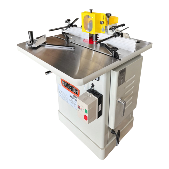
Page 19: Getting To Know Your Machine
GETTING TO KNOW YOUR MACHINE Spindle Height Magnetic Safety Switch B Cabinet Handwheel Table Extension Miter Gauge Main Table Workpiece Hold Down Guard Guard Lock Knob Dust Hood Assembly Fence Micro Adjustment L Guide Fence Forward/Reverse Motor Access Door Power Cord Switch... - Page 20 Contents Contents Qty. Contents Qty. Vertical Safety Guard w/Lenses Guard Knobs and Washers Dust Hood / Guard Assembly Router Adapter (1/2” & 1/4”) Horizontal Guard Spindle 1/2” Hold Down Plate Spindle 3/4” Fence Rail Hood Lock Lever and Washers Draw Bar Fence Lock Lever Handle Tension Bar Retainer Clamp...
-
Page 21: Assembly And Set Up
ASSEMBLY AND SET UP WARNING: For your own safety, DO NOT connect the machine to the power source until the machine is completely assembled and you read and understand the entire instruction manual. Table Extension The shaper has one extension wing that installs on the front of the main table. -
Page 22: Handwheel Handle Installation
3. Install the T-bolt portion (C) of the fence lock lever assembly into the T-slot on the fence. 4. Insert the threads of the T-bolt through the fence mounting slot (D) and install and lightly tighten the lock lever (E) to hold the fence in position. 5. -
Page 23: Spindle / Collet Installation
Spindle / Collet Installation The shaper is supplied with both 1/2" and 3/4” spindle assemblies. These assemblies are locked in a tapered seat with a draw bar and nut. 1. To change spindles, disconnect the shaper from the power source. 2. -
Page 24: Attaching Cutters And Collars To Spindles
Attaching Cutters and Collars to Spindles Each size spindle is supplied with a safety lock nut with left hand threads located above the larger spindle nut. To mount or change cutters, first remove the safety lock nut (A). Remove the spindle nut (B) by placing one wrench on the spindle nut and another wrench on the flats on top of the spindle. -
Page 25: Setting Table Inserts
Setting Table Inserts The table inserts are preinstalled at the factory. They should be adjusted so that the top surface of the insert is level with the tabletop. If any adjustment is necessary: 1. Place a straight edge across the inserts and table top to determine if the inserts are level, high, or low as compared to the table top. -
Page 26: Electrical
ELECTRICAL CAUTION: HAVE ELECTRICAL UTILITIES CONNECTED TO MACHINE BY A CERTIFIED ELECTRICIAN! Check if the available power supply is the same as listed on the machine nameplate. WARNING: Make sure the grounding wire (green) is properly connected to avoid electric shock. DO NOT switch the position of the green grounding wire if any electrical plug wires are switched during hookup. -
Page 27: Power Cord Connection
• Improper connection of the equipment-grounding conductor can result in risk of electric shock. The conductor with insulation having an outer surface that is green with or without yellow stripes is the equipment-grounding conductor. If repair or replacement of the electric cord or plug is necessary, do not connect the equipment-grounding conductor to a live terminal. -
Page 28: Adjustments
ADJUSTMENTS Check all mounting screws and bolts to see that they are tight. CAUTION: When changing tools, adjusting the drive belt, or doing cleanup and maintenance, always turn the machine off and unplug the machine from its power source. Fence Positioning & Alignment Fence Positioning The fence adjustment largely involves moving the fence forward or aft to expose more or less of the cutting blade. -
Page 29: Raising And Lowering The Spindle
Raising and Lowering the Spindle The Spindle can be raised or lowered by turning the handwheel (A). 1. Loosen the spindle height lock knob on the side of the left side of the cabinet. 2. To raise the spindle height, turn the handwheel clockwise. -
Page 30: Operation
OPERATION WARNING: For the sake of clarity, the shaper guard has been omitted from most illustrations. All shaper operations must be done with the proper guard in place and any other device which ensures the safety of the operator. CAUTION: Always wear proper eye protection with side shields, face shield, safety footwear, and leather gloves to protect from, chips, dust, burrs, and slivers. -
Page 31: Rotation
Rotation CAUTION: Always check the direction of cutter rotation before any shaping operation. Cutters rotating backwards will cause unsafe conditions. Your shaper is equipped with a FORWARD/ REVERSE switch (A). In many instances, it will be necessary to flip the cutter over and reverse cutter rotation. Whenever possible, mount the cutter so the board is milled on the bottom side (the side away from the operator). -
Page 32: Using Collars
Freehand Shaping Freehand Shaping is shaping without the use of a miter gauge or fence. 1. Beginning the cut is the most dangerous part of freehand shaping. Many times when the workpiece first contacts the cutter, the workpiece will tend to kickback or jerk, which can surprise the operator. -
Page 33: Counter Clock Wise Setup
Between two Cutters The advantage of this setup is that you can make two profile cuts in a single pass so it is frequently used when both edges of the workpiece are to be shaped. The disadvantage with this method, like the “Below the Cutter”... -
Page 34: Straight Edge Shaping
Straight Edge Shaping Straightedge shaping is always performed with the work piece against the fence. To set up: 1. UNPLUG OR DISCONNECT SHAPER FROM POWER SOURCE AND LOCK OUT POWER. 2. Check to see that the fence faces are parallel, properly in line or offset if necessary, and securely tightened. -
Page 35: Edge Shaping: Long Boards
Edge Shaping: Long Boards When edge shaping ling boards, the work piece must be at least 12 inches long. 1. Use the hold-in and hold-down plates as shown in figure to firmly hold the work piece down and against the fence. If work piece is too wide for the hold-ins to be used, clamp a scrap board to the table to substitute for the hold-ins. -
Page 36: On-Edge Shaping
On-Edge Shaping If the shaper fence does not firmly support wide stock, use the existing bolts in the fence to attach a special rigid high fence. Note: Be sure the bolt holes are countersunk in the special fence. End Shaping WARNING: End shaping a narrow workpiece without a special guide could result in the workpiece rocking into the cutterhead causing minor, or major,... -
Page 37: Contour Edge Shaping With Collar Bearing
Contour Edge Shaping with Collar Bearing To shape contoured edges, the operator must first remove the fence assembly. In order to control the workpiece and limit the depth-of-cut, the operator must use an anti-friction collar with the cutter(s). The collar may be positioned above or below the cutter (s), and its function is to ride against the workpiece or template. - Page 38 When the workpiece is not contoured all around, start the cut as shown. With this operation, the workpiece is positioned against the start pin and the end swung into place to start the cut. When the cut has begun and the work piece firmly against the collar, swing the stock away from the pin and proceed with cut.
-
Page 39: Enclosed Edge Shaping
Enclosed Edge Shaping WARNING: Enclosed edge shaping is extremely dangerous. The operator must be aware at all times of the direction of feed. WARNING: Unless the workpiece is attached to a larger wooden base, NEVER perform enclosed edge shaping if there is less than 12” of workpiece material all around the opening. -
Page 40: Templates
Templates The template, which is usually made of 3/4” scrap material, must be thick enough to provide a solid bearing edge against a collar. When constructing a template similar to the one shown, keep in mind that it serves only as a guide for the cutter. -
Page 41: Horizontal Toggle Clamp
Horizontal Toggle Clamp The horizontal toggle clamp, similar to those illustrated, is especially useful when ordinary “C” clamps will not allow the freedom of movement often required in shaping. The toggle clamp also allows the operator to firmly control the workpiece without the additional pressure required to keep workpiece and template together by hand. - Page 42 This figure shows the first shaping cut with the sash cutter for the matching door stile sash. This is the same cut with the stock flipped. This figure shows the first shaping out for a window-sash stile utilizing a sash cutter, collar, collar, and a 1/2" groove cutter.
-
Page 43: Butt Joints
Butt Joints All butt type joints require both workpieces to be perfectly square and straight-edged. Glue Butt Joint: To perform a glue butt joint, both fences are kept in-line and adjusted for a depth of cut. The cuts on both workpieces are part-edge cuts which do not reduce the stock width during the cutting procedure. -
Page 44: Tenoning
Tenoning The tenoning fixture illustrated, shows a miter gauge equipped with a hold down for shaping the ends of narrow workpieces. The miter gauge can also be adapted to cut square and centered tenons at the ends of legs for tables, chairs, etc. -
Page 45: Maintenance
MAINTENANCE WARNING: Make sure the electrical disconnect is OFF before working on the machine. Maintenance should be performed on a regular basis following proper safety precautions. This shaper requires very little maintenance other than minor lubrication and cleaning. The following sections detail what will need to be done in order to assure continued operation of your shaper. -
Page 46: Lubrication
Lubrication The only parts on this machine that require periodic lubrication are the ways where the cartridge slide rides on the elevation housing and where the worm gear and bushing are located. Use a light grease or anti-seizing compound on the ways and worm gear and give the shaft mount a shot of light oil. -
Page 47: Cabinet Parts Diagram
CABINET PARTS DIAGRAM... -
Page 48: Motor And Quill Parts Diagram
MOTOR AND QUILL PARTS DIAGRAM... -
Page 49: Spindle Parts Diagram
SPINDLE PARTS DIAGRAM... -
Page 50: Fence And Hood Parts Diagram
FENCE AND HOOD PARTS DIAGRAM... -
Page 51: Parts List
Parts List Item Part No. Description Qty. SS2725-1 Stand Assembly SS2725-2N Switch SS2725-3 Screw 5/32" X 1"L SS2725-3A Screw 5/32" X 4"L SS2725-4 Forward-Reverse Switch SS2725-4A Forward-Reverse Switch Cover SS2725-4B Connector SS2725-5 Nut. Hex 5/32" SS2725-6 SS2725-7 Miter Gauge SS2725-8 Screws Set 5/16"... - Page 52 Item Part No. Description Qty. SS2725-30 SS2725-31 Set Screw 5/16" X 3/8" SS2725-32 Motor Pulley SS2725-33 Knob SS2725-34 Motor Base SS2725-35 Motor SS2725-36 Screw 5/16" X 5/8" SS2725-37 Spring SS2725-38 Spring Shaft SS2725-39 Washer 1/2" SS2725-40 Spring Washer 1/4" SS2725-41 Screw 1/4"...
- Page 53 Item Part No. Description Qty. SS2725-65 Gear Washer SS2725-66 Gear SS2725-67 Collar SS2725-68 SS2725-69 Gear Shaft SS2725-70 Hex Nut 5/8" SS2725-71 Hex Nut 3/4" SS2725-72 Collar 3/4" X 1/2" SS2725-73 Collar 3/4" X 3/4" SS2725-74 Collar 3/4" X 1" SS2725-75 Spindle 3/4"...
- Page 54 Item Part No. Description Qty. SS2725-111 Lock Lever SS2725-112 Washer SS2725-113 Knob SS2725-114 Knob SS2725-115 Screw SS2725-116 Bolt SS2725-117 Fence Travel Bushing SS2725-118 Lock Handle SS2725-119 Washer SS2725-120 Bracket SS2725-121B T-Screw SS2725-122B Fence SS2725-123 Bolt SS2725-124 Set Screw SS2725-125 Knob Screw SS2725-126 T-Hex Nut 3/8"...
- Page 55 NOTES...
- Page 56 BAILEIGH INDUSTRIAL 1625 D , WI 54220 UFEK RIVE ANITOWOC : 920. 684. 4990 F : 920. 684. 3944 HONE www.baileigh.com...