Table of Contents
Advertisement
Quick Links
OPERATOR'S MANUAL
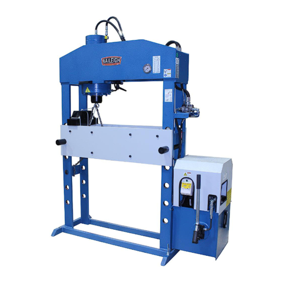
66 TON HYDRAULIC SHOP PRESS
MODEL: HSP-66M-HD
Baileigh Industrial, Inc.
P.O. Box 531
Manitowoc, WI 54221-0531
Phone: 920.684.4990
Fax: 920.684.3944
sales@baileigh.com
REPRODUCTION OF THIS MANUAL IN ANY FORM WITHOUT WRITTEN APPROVAL OF BAILEIGH INDUSTRIAL, INC.
IS PROHIBITED. Baileigh Industrial, Inc. does not assume and hereby disclaims any liability for any damage or loss
caused by an omission or error in this Operator's Manual, resulting from accident, negligence, or other occurrence.
Rev. 1/2017
© 2017 Baileigh Industrial, Inc.
Advertisement
Table of Contents

Related Manuals for Baileigh Industrial HSP-66M-HD


Summary of Contents for Baileigh Industrial HSP-66M-HD
- Page 1 REPRODUCTION OF THIS MANUAL IN ANY FORM WITHOUT WRITTEN APPROVAL OF BAILEIGH INDUSTRIAL, INC. IS PROHIBITED. Baileigh Industrial, Inc. does not assume and hereby disclaims any liability for any damage or loss caused by an omission or error in this Operator’s Manual, resulting from accident, negligence, or other occurrence.
-
Page 2: Table Of Contents
Table of Contents THANK YOU & WARRANTY ..................1 INTRODUCTION ......................3 GENERAL NOTES ......................3 SAFETY INSTRUCTIONS ....................4 SAFETY PRECAUTIONS ....................6 Dear Valued Customer: ....................6 TECHNICAL SPECIFICATIONS ..................9 TECHNICAL SUPPORT ....................9 UNPACKING AND CHECKING CONTENTS ..............10 Cleaning ........................ - Page 3 ELECTRIC HYDRAULIC PUMP PARTS DIAGRAM ............. 38 Electric Hydraulic Pump Parts List ................39 ELECTRICAL SCHEMATIC ..................40 ELECTRICAL PARTS LIST ..................41 HYDRAULIC PARTS LIST .................... 41 HYDRAULIC DIAGRAM ....................42 TROUBLESHOOTING ....................43...
-
Page 4: Thank You & Warranty
THANK YOU & WARRANTY Thank you for your purchase of a machine from Baileigh Industrial. We hope that you find it productive and useful to you for a long time to come. Inspection & Acceptance. Buyer shall inspect all Goods within ten (10) days after receipt thereof. Buyer’s payment shall constitute final acceptance of the Goods and shall act as a waiver of the Buyer’s rights to inspect or... - Page 5 A 30% re-stocking fee applies to all returns. Baileigh Industrial makes every effort to ensure that our posted specifications, images, pricing and product availability are as correct and timely as possible. We apologize for any discrepancies that may occur. Baileigh Industrial reserves the right to make any and all changes deemed necessary in the course of business including but not limited to pricing, product specifications, quantities, and product availability.
-
Page 6: Introduction
After receiving your equipment remove the protective container. Do a complete visual inspection, and if damage is noted, photograph it for insurance claims and contact your carrier at once, requesting inspection. Also contact Baileigh Industrial and inform them of the unexpected occurrence. Temporarily suspend installation. -
Page 7: Safety Instructions
IMPORTANT PLEASE READ THIS OPERATORS MANUAL CAREFULLY It contains important safety information, instructions, and necessary operating procedures. The continual observance of these procedures will help increase your production and extend the life of the equipment. SAFETY INSTRUCTIONS LEARN TO RECOGNIZE SAFETY INFORMATION This is the safety alert symbol. - Page 8 SAVE THESE INSTRUCTIONS. Refer to them often and use them to instruct others. PROTECT EYES Wear safety glasses or suitable eye protection when working on or around machinery. PROTECT AGAINST NOISE Prolonged exposure to loud noise can cause impairment or loss of hearing.
-
Page 9: Safety Precautions
HIGH VOLTAGE USE CAUTION IN HIGH VOLTAGE AREAS. DO NOT assume the power to be off. FOLLOW PROPER LOCKOUT PROCEDURES. EMERGENCY STOP BUTTON In the event of incorrect operation or dangerous conditions, the machine can be stopped immediately by pressing the E-STOP button. Twist the emergency stop button clockwise (cw) to reset. - Page 10 ! ..P SAFELY! LEASE ENJOY YOUR AILEIGH MACHINE LEASE ENJOY IT 1. Only trained and qualified personnel can operate this machine. 2. Make sure guards are in place and in proper working order before operating machinery. 3. Remove any adjusting tools. Before operating the machine, make sure any adjusting tools have been removed.
- Page 11 18. DO NOT touch live electrical components or parts. 19. Turn off power before checking, cleaning, or replacing any parts. 20. Be sure all equipment is properly installed and grounded according to national, state, and local codes. 21. Inspect power and control cables periodically. Replace if damaged or bare wires are exposed.
-
Page 12: Technical Specifications
TECHNICAL SPECIFICATIONS Press Power 66tons (60metric tons) Maximum pressure 3814psi (263bar) 9.85” (250mm) Stroke Piston diameter Ø7.08”x4.72”mm (Ø180x120mm) .31”/sec) (8mm/sec) Advance Speed Working Speed .16”/sec) (4mm/sec) .39”/sec) (10mm/sec) Return Speed 40.94” (1040mm) Table Width Power 220V, 3ph, 60hz Motor 5.3hp (4kw) 220V / 3ph / 60hz / 15A Oil Capacity 15.85gal (60L) Oil Type... -
Page 13: Unpacking And Checking Contents
UNPACKING AND CHECKING CONTENTS Your Baileigh machine is shipped complete. Separate all parts from the packing material and check each item carefully. Make certain all items are accounted for before discarding any packing material. WARNING: SUFFOCATION HAZARD! Immediately discard any plastic bags and packing materials to eliminate choking and suffocation hazards to children and animals. -
Page 14: Transporting And Lifting
TRANSPORTING AND LIFTING IMPORTANT: Lifting and carrying operations should be carried out by skilled workers, such as a truck operator, crane operator, etc. If a crane is used to lift the machine, attach the lifting chain carefully, making sure the machine is well balanced. Follow these guidelines when lifting with truck or trolley: ... -
Page 15: Installation
Check if the load is properly balanced by lifting it an inch or two. Lift the machine, avoiding sudden accelerations or quick changes of direction. Locate the machine where it is to be installed, and lower slowly until it touches the floor. INSTALLATION IMPORTANT: Consider the following when looking for a suitable location to place the machine:... -
Page 16: Anchoring The Machine
Anchoring the Machine WARNING: Before operating the press, make sure it is firmly anchored the floor. If it tips over on you, it could cause severe injury or death. Once positioned, anchor the machine to the floor, as shown in the diagram, using bolts and expansion plugs or sunken tie rods that connect through holes in the base of the stand. -
Page 17: Foundation Diagram
FOUNDATION DIAGRAM... -
Page 18: Dimensions
DIMENSIONS 40.94” 82.67” 70.86” 34.45” 10.23” 27.56” 53.34” (1040mm) (1355mm) (2100mm) (1800mm) (875mm) (260mm) (700mm) Table Holes – Center to Center 6.5” (165mm) 2.25” (57mm) Minimum Table to Ram Height (Cap ON) 34.875” (885mm) Maximum Table to Ram Height (Cap ON) - Page 19 91.34” 104.7” 31.49” 27.56” 31.49” 15.75” 73.23” 15.75” (2320mm) (2660mm) (800mm) (700mm) (800mm) (400mm) (1860mm) (400mm)
-
Page 20: Getting To Know Your Machine
GETTING TO KNOW YOUR MACHINE... - Page 21 Item Description Main Frame; Supports the entire machine components and work material. Support Pins; Supports the work table at the desired work height. Heal Blocks / V-Blocks; used to support the material during the pressing operation. Work Table Lift Chain; Used to lift and lower the work table using the cylinder to provide the lifting and lowering force.
-
Page 22: Electrical
ELECTRICAL WARNING: Baileigh Industrial is not responsible for any damage caused by wiring up to an alternative 3-phase power source other than direct 3-phase. If you are using an alternate power source, consult a certified electrician or contact Baileigh Industrial prior to energizing the machine. -
Page 23: Power Cord Connection
WARNING: Make certain any receptacle in question is properly grounded. If you are not sure, have a qualified electrician check the receptacle Improper connection of the equipment-grounding conductor can result in risk of electric shock. The conductor with insulation having an outer surface that is green with or without yellow stripes is the equipment-grounding conductor. -
Page 24: Operation Preplanning
OPERATION PREPLANNING This is a general discussion on press operation and is not intended to be an exact step-by-step procedure. This is intended to create a broad thought process to be considered prior to using the press to stimulate the operator into thinking about as many possible scenarios that could cause injury or material damage. -
Page 25: General Information
Fasteners and Retainers: Make sure that all retaining rings, pins, or fasteners are removed, and no hidden secondary retainers are present. Hidden Objects: Some components house one or more pieces such and springs, retaining rings, or spacers. Make sure that the part to be dismantled with the press has the applicable caging system to catch hidden items. -
Page 26: Press Functions
PRESS FUNCTIONS On /Off Switch The On / Off switch is located on the front of the electrical panel on top of the hydraulic tank. Turn the switch to the ON position to supply power to the electrical controls. The indicator light on the electrical box will light up as long as the switch is ON. -
Page 27: Direction Control Valve
Direction Control Valve The direction control valve is located on the right side of the press frame. The valve has 4 lever (A) positions labeled Fast 2, Slow 1, Stop 0, and Back R. Stop 0 position: When the lever has not been operated, the valve will always return to this position. -
Page 28: Pressure Regulation Valve
Pressure Regulation Valve CAUTION: NEVER EXCEED THE MAXIMUM PRESSURE SETTING! The pressure regulation valve is located on the hydraulic control valve. With this valve the maximum pressure, referring to the maximum press capacity, can be changed. Turning the adjustment clockwise will increase the pressure, turning the adjustment counter clockwise will decrease the pressure. -
Page 29: Air Purge
Air Purge When starting up for the first time or when maintenance on the hydraulic system has been performed, the hydraulic system needs to be purged. 1. Make sure there is no work piece on the table. 2. Start the hydraulic unit. 3. - Page 30 Table Adjustment IMPORTANT: NEVER lift or lower the table with tooling or material or pressure from the ram on the table. This will damage the machine voiding the warranty. Lifting the table is performed using the lifting chain attached from the ram to the table. 1.
-
Page 31: Using The Machine
Using the Machine: Incorrect Correct... - Page 32 Incorrect Correct...
-
Page 33: Operation
OPERATION CAUTION: Always wear proper eye protection with side shields, safety footwear, and leather gloves to protect from burrs and sharp edges. 1. Place the work piece on the table so that it is aligned with the piston rod. If this is not possible, reposition the cylinder to achieve the best alignment. -
Page 34: Understanding Springback
UNDERSTANDING SPRINGBACK Springback, also known as elastic recovery, is the result of the metal wanting to return to its original shape after undergoing compression and stretch. After the bending leaf is removed from the metal and the load is released, the piece part relaxes, forcing the bent portion of the metal to return slightly to its original shape. -
Page 35: Lubrication And Maintenance
LUBRICATION AND MAINTENANCE WARNING: Make sure the electrical disconnect is OFF before working on the machine. Maintenance should be performed on a regular basis by qualified personnel. Always follow proper safety precautions when working on or around any machinery. Note: Proper maintenance can increase the life expectancy of your machine. Daily Maintenance ... -
Page 36: Changing The Hydraulic Oil
Two Year Maintenance Replace the hydraulic oil of the unit. Changing the Hydraulic Oil The hydraulic oil is the primary medium for transmitting pressure and also must lubricate the running parts of the pump. Replace the hydraulic oil at least once a year. 1. -
Page 37: Overall Machine Parts Diagram
OVERALL MACHINE PARTS DIAGRAM... -
Page 38: Overall Machine Parts List
Overall Machine Parts List Item Description Mail Frame Cylinder Pressure Gauge Plate Plate Fixing Shaft Bolt Plate Shaft... -
Page 39: Ram Parts Diagram
RAM PARTS DIAGRAM... -
Page 40: Ram Parts List
Ram Parts List Item Description Cylinder Cylinder Cap Neck Flange Dust Cap Cylinder Flange Piston Compact Seal Teflon Stripe O–Ring Scraper Neck Seal Bushing Band Press Frame Bolt... -
Page 41: Electric Hydraulic Pump Parts Diagram
ELECTRIC HYDRAULIC PUMP PARTS DIAGRAM... -
Page 42: Electric Hydraulic Pump Parts List
Electric Hydraulic Pump Parts List Item Description Head Arm Control Pressure Pipe Crossover Tube Emergency Vent Block Block Bolts Distributer Block Absorb Pipe Absorb Filter Block Pressure Bolt Connecting Bolt Connecting Plate O – Ring Hydraulic Pump O – Ring Connecting Plate Oil Sight Gauge And Temperature Read–Out Pressure Bolt... -
Page 43: Electrical Schematic
ELECTRICAL SCHEMATIC... -
Page 44: Electrical Parts List
ELECTRICAL PARTS LIST Item Description Motor Protection Overload Thermal Relay (6-10A) (GV2 ME14 Telemecanique) Indicator Lamp (GV2 SN33 Telemecanique) Voltage Trips (GVAU385 Telemecanique) Enclosure (Plastic Box) (GV2 MC01 Telemecanique) Emergency Stop Module (GV2 K021 Telemecanique) HYDRAULIC PARTS LIST Item Description Specification Qty. -
Page 45: Hydraulic Diagram
HYDRAULIC DIAGRAM... -
Page 46: Troubleshooting
TROUBLESHOOTING WARNING: Make sure the electrical disconnect is OFF before working on the machine. FAULT PROBABLE CAUSE REMEDY Check pressure gauge. Repair or Gauge Failure replace as needed. Plugged oil passage in relief Clean valve(s). Replace if needed. valve or check valve. Low Pressure Check and tighten any loose or leaking Oil leak at hose fittings. - Page 47 NOTES...
- Page 48 , WI 54220 UFEK RIVE ANITOWOC : 920. 684. 4990 F : 920. 684. 3944 HONE www.baileigh.com BAILEIGH INDUSTRIAL, INC. 1455 S. C , CA 91761 AMPUS VENUE NTARIO : 920. 684. 4990 F : 920. 684. 3944 HONE BAILEIGH INDUSTRIAL LTD. U...
Need help?
Do you have a question about the HSP-66M-HD and is the answer not in the manual?
Questions and answers