Table of Contents
Advertisement
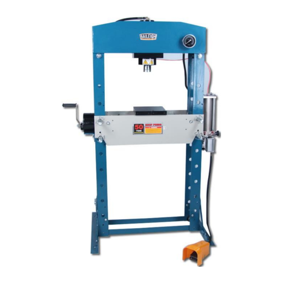
OPERATOR'S MANUAL
50 TON SHOP PRESS
MODEL: HSP-50A
Baileigh Industrial Holdings LLC
P.O. Box 531
Manitowoc, WI 54221-0531
Phone: 920.684.4990
Fax: 920.684.3944
sales@baileigh.com
REPRODUCTION OF THIS MANUAL IN ANY FORM WITHOUT WRITTEN APPROVAL OF BAILEIGH INDUSTRIAL
HOLDINGS LLC IS PROHIBITED. Baileigh Industrial Holdings LLC, Inc. does not assume and hereby disclaims any
liability for any damage or loss caused by an omission or error in this Operator's Manual, resulting from accident,
negligence, or other occurrence.
Rev. 10/2019
© 2019 Baileigh Industrial Holdings LLC
Advertisement
Table of Contents

Related Manuals for Baileigh Industrial HSP-50A


Summary of Contents for Baileigh Industrial HSP-50A
- Page 1 REPRODUCTION OF THIS MANUAL IN ANY FORM WITHOUT WRITTEN APPROVAL OF BAILEIGH INDUSTRIAL HOLDINGS LLC IS PROHIBITED. Baileigh Industrial Holdings LLC, Inc. does not assume and hereby disclaims any liability for any damage or loss caused by an omission or error in this Operator’s Manual, resulting from accident, negligence, or other occurrence.
-
Page 2: Table Of Contents
Table of Contents THANK YOU & WARRANTY ..................1 INTRODUCTION ......................3 GENERAL NOTES ......................3 SAFETY INSTRUCTIONS ....................4 SAFETY PRECAUTIONS ....................6 Dear Valued Customer: ....................6 MACHINE SAFETY LABELS ..................8 TECHNICAL SPECIFICATIONS ..................9 TECHNICAL SUPPORT ....................9 UNPACKING AND CHECKING CONTENTS .............. -
Page 3: Thank You & Warranty
THANK YOU & WARRANTY Thank you for your purchase of a machine from Baileigh Industrial Holdings LLC. We hope that you find it productive and useful to you for a long time to come. Inspection & Acceptance. Buyer shall inspect all Goods within ten (10) days after receipt thereof. Buyer’s payment shall constitute final acceptance of the Goods and shall act as a waiver of the Buyer’s rights to inspect or... - Page 4 We apologize for any discrepancies that may occur. Baileigh Industrial Holdings LLC reserves the right to make any and all changes deemed necessary in the course of business including but not limited to pricing, product specifications, quantities, and product availability.
-
Page 5: Introduction
INTRODUCTION The quality and reliability of the components assembled on a Baileigh Industrial Holdings LLC machine guarantee near perfect functioning, free from problems, even under the most demanding working conditions. However, if a situation arises, refer to the manual first. If a solution cannot be found, contact the distributor where you purchased our product. -
Page 6: Safety Instructions
IMPORTANT PLEASE READ THIS OPERATORS MANUAL CAREFULLY It contains important safety information, instructions, and necessary operating procedures. The continual observance of these procedures will help increase your production and extend the life of the equipment. SAFETY INSTRUCTIONS LEARN TO RECOGNIZE SAFETY INFORMATION This is the safety alert symbol. - Page 7 SAVE THESE INSTRUCTIONS. Refer to them often and use them to instruct others. PROTECT EYES Wear safety glasses or suitable eye protection when working on or around machinery. PROTECT AGAINST NOISE Prolonged exposure to loud noise can cause impairment or loss of hearing.
-
Page 8: Safety Precautions
SAFETY PRECAUTIONS Metal working can be dangerous if safe and proper operating procedures are not followed. As with all machinery, there are certain hazards involved with the operation of the product. Using the machine with respect and caution will considerably lessen the possibility of personal injury. However, if normal safety precautions are overlooked or ignored, personal injury to the operator may result. - Page 9 7. Dressing material edges. Always chamfer and deburr all sharp edges. 8. Do not force tool. Your machine will do a better and safer job if used as intended. DO NOT use inappropriate attachments in an attempt to exceed the machines rated capacity. 9.
-
Page 10: Machine Safety Labels
MACHINE SAFETY LABELS... -
Page 11: Technical Specifications
TECHNICAL SPECIFICATIONS Maximum Capacity 50 ton (45 ton) Hydraulic System Pressure 9053psi. (62.42MPa) Moveable Cylinder 28.5” (724mm) Working Width 7.8” (200mm) Cylinder Stroke 6” (152mm) Cylinder Diameter 2” (50.8mm) Piston Rod Diameter 2.75” (70mm) Piston Head Diameter 2.4” ~ 41” (62 ~ 1042mm) Working Range Power Requirement Pneumatic/Manual... -
Page 12: Unpacking And Checking Contents
UNPACKING AND CHECKING CONTENTS Your Baileigh machine is shipped complete. Separate all parts from the packing material and check each item carefully. Make certain all items are accounted for before discarding any packing material. WARNING: SUFFOCATION HAZARD! Immediately discard any plastic bags and packing materials to eliminate choking and suffocation hazards to children and animals. -
Page 13: Transporting And Lifting
TRANSPORTING AND LIFTING NOTICE: Lifting and carrying operations should be carried out by skilled workers, such as a truck operator, crane operator, etc. If a crane is used to lift the machine, attach the lifting chain carefully, making sure the machine is well balanced. Follow these guidelines when lifting with truck or trolley: •... -
Page 14: Installation
INSTALLATION IMPORTANT: Consider the following when looking for a suitable location to place the machine: • Overall weight of the machine. • Weight of material being processed. • Sizes of material to be processed through the machine. • Space needed for auxiliary stands, worktables, or other machinery. •... -
Page 15: Anchoring The Machine
Anchoring the Machine WARNING: Before operating the press, make sure it is firmly anchored the floor. If it tips over on you, it could cause severe injury or death. • Once positioned, anchor the machine to the floor, as shown in the diagram. -
Page 16: Overall Dimensions
OVERALL DIMENSIONS 8.00" [203.20] 29.00" 9.00" [736.60] [228.60] 10.00" [254.00] 36.00" 31.50" [914.40] [800.10] 40.62" [1031.85] 52.75" [1339.85] 38.12" [968.35] 1.25" [31.75]... - Page 17 Provide adequate clearance for the equipment in an environment that is clean, non-flammable, non-corrosive, and dust free. 40.00" [1016.00] 40.00" [1016.00]...
-
Page 18: Getting To Know Your Machine
GETTING TO KNOW YOUR MACHINE Hardware... - Page 19 Item Description Base Angles Hex Bolt M12 x 35mm Brace Supports Hex Nut M12 Lock Washer M12 Flat Washer M12 Bed Frame Pin Circlip Bed Frame Heel Block Main Frame w/Hydraulics Pressure Gauge Hex Bolt M10 x 20mm Flat Washer M10 Handle...
-
Page 20: Assembly
ASSEMBLY Mounting Support Structure While the base (32) is lying on its side, slide the bed frame (23) from the bottom of the base. This provides for better access when attaching the lower support structure. 1. Attach the base section angle (01) to the base (32) with two M12 x 35mm hex bolts (02), flat washers (06), lock washers (05), and nuts (04). - Page 21 Hanging the Cylinder Assembly 1. Move the cylinder assembly (34) to the outside of the base frame (32) as shown and attach to the frame members using four M10 x 20mm hex bolts (47) and flat washers (48). Tighten securely. Position the foot operated air valve on the floor. Attaching Hydraulic Lines 1.
-
Page 22: Setup And Adjustments
Mounting the Bed Frame Winch 1. Move the hand winch (11) to the outside of the frame and attach the angle to the flatbar member with two M10 x 20mm lg. hex bolts (02), flat washers (06), lock washers (05), and M10 hex nuts (04). -
Page 23: Purging The System
Purging the System Air-In 1. Securely fasten this hydraulic press to a level concrete floor. Fitting 2. Make sure there is adequate lighting and a 40” (1,016mm) minimum clearance around the entire machine. 3. Before using for the first time, pour a teaspoon of good quality air tool lubricant into the air supply inlet of the lift control valve. - Page 24 3. Preload the workpiece prior to proceeding with the full pressing operation. 4. View the setup from various angles and verify that the ram remains aligned with and centered with the workpiece and the bed. 5. Relieves the hydraulic pressure and allows the ram to return to the retracted position. WARNING: Failure to center the piece part on the blocks and the ram to the piece part may cause serious injury.
-
Page 25: Operation
OPERATION CAUTION: Always wear proper eye protection with side shields, safety footwear, and leather gloves to protect from burrs and sharp edges. Moving the Bed Frame IMPORTANT: NEVER lift or lower the bed with tooling or material or pressure from the ram on the bed. -
Page 26: Sequence Of Operation
Sequence of Operation 1. Insert the piece part into the V-blocks or onto the flat blocks. 2. Close the release valve (50) by turning it clockwise (cw) until it is off. 3. Connect the quick air valve air-in fitting to a 120 psi. (.83 MPa) air source. 4. -
Page 27: Material Selection
MATERIAL SELECTION CAUTION: It must be determined by the customer that materials being processed through the machine are NOT potentially hazardous to operator or personnel working nearby. When selecting materials keep these instructions in mind: • Material must be clean and dry. (without oil) •... -
Page 28: Checking The Hydraulic Oil
Checking the Hydraulic Oil Oil Fill 1. Remove the oil filler nut on top of the reservoir. 2. If oil is low, refill with 22 ISO6743 hydraulic jack oil or equivalent. 3. Replace the oil fill nut. 4. Purge air from the hydraulic system. Checking the Cable Check integrity of bed frame lift system. -
Page 29: Parts Diagram
PARTS DIAGRAM... -
Page 30: Parts List
Parts List Item Description Qty. Item Description Qty. Base Section Bolt Bolt Ram Assembly Support Bolt Screw Lock Washer Serrated Saddle Washer Pressure Gauge Nylon Ring Circlip Gauge Fitting Roller Connecting Plate HCS M12-1.75 x 35 Zinc O-Ring Hand Winch Junction Rod Bed Frame Pin Bolt... - Page 31 Item Description Qty. Item Description Qty. Connecting Plate Cable Cable...
-
Page 32: Parts Identification - Main Cylinder
PARTS IDENTIFICATION – MAIN CYLINDER... -
Page 33: Parts List - Main Cylinder
Parts List – Main Cylinder Item Description Qty. Ring for ram O-ring O-ring Screw Copper Washer Ring O-ring Circlip Valve rod Ball Spring Screw Nylon Screw Ring O-ring Spring Cylinder Screw Ring Fitting... -
Page 34: Hydraulic Schematic
HYDRAULIC SCHEMATIC Handle... -
Page 35: Troubleshooting
Air Motor Does Not Work. Air motor is damaged. Replace the air motor. Contact Baileigh Industrial at 920.684.4990 Damaged or worn out cylinder Replace the seals. seals. Leaking oil Screwed parts loose. Re-tighten screws. Damaged hose or hoses. Contact Baileigh Industrial at 920.684.4990... - Page 36 BAILEIGH INDUSTRIAL HOLDINGS LLC 1625 D , WI 54220 UFEK RIVE ANITOWOC : 920. 684. 4990 F : 920. 684. 3944 HONE www.baileigh.com BAILEIGH INDUSTRIAL HOLDINGS LTD. U WIFT OINT WIFT ALLEY NDUSTRIAL STATE UGBY , CV21 1QH U IDLANDS...
Need help?
Do you have a question about the HSP-50A and is the answer not in the manual?
Questions and answers