Table of Contents
Advertisement
OPERATOR'S MANUAL
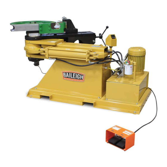
ROTARY DRAW BENDER
MODEL: RDB-500
Baileigh Industrial, Inc.
P.O. Box 531
Manitowoc, WI 54221-0531
Phone: 920.684.4990
Fax: 920.684.3944
sales@baileigh.com
REPRODUCTION OF THIS MANUAL IN ANY FORM WITHOUT WRITTEN APPROVAL OF BAILEIGH INDUSTRIAL, INC.
IS PROHIBITED. Baileigh Industrial, Inc. does not assume and hereby disclaims any liability for any damage or loss
caused by an omission or error in this Operator's Manual, resulting from accident, negligence, or other occurrence.
Rev. 03/2015
© 2015 Baileigh Industrial, Inc.
Advertisement
Table of Contents

Related Manuals for Baileigh Industrial RDB-500


Summary of Contents for Baileigh Industrial RDB-500
- Page 1 REPRODUCTION OF THIS MANUAL IN ANY FORM WITHOUT WRITTEN APPROVAL OF BAILEIGH INDUSTRIAL, INC. IS PROHIBITED. Baileigh Industrial, Inc. does not assume and hereby disclaims any liability for any damage or loss caused by an omission or error in this Operator’s Manual, resulting from accident, negligence, or other occurrence.
-
Page 2: Table Of Contents
Table of Contents THANK YOU & WARRANTY ..................1 INTRODUCTION ......................3 GENERAL NOTES ......................3 SAFETY INSTRUCTIONS ....................4 SAFETY PRECAUTIONS ....................7 TECHNICAL SPECIFICATIONS ..................9 TECHNICAL SUPPORT ....................9 UNPACKING AND CHECKING CONTENTS ..............10 Cleaning ........................10 TRANSPORTING AND LIFTING .................. - Page 3 Lead Screw Assembly Parts Diagram ............... 42 Encoder Assembly Parts Diagram ................43 Adaptor Plate Assembly Parts Diagram ..............44 Parts List ........................45...
-
Page 4: Thank You & Warranty
THANK YOU & WARRANTY Thank you for your purchase of a machine from Baileigh Industrial. We hope that you find it productive and useful to you for a long time to come. Inspection & Acceptance. Buyer shall inspect all Goods within ten (10) days after receipt thereof. Buyer’s payment shall constitute final acceptance of the Goods and shall act as a waiver of the Buyer’s rights to inspect or... - Page 5 A 30% re-stocking fee applies to all returns. Baileigh Industrial makes every effort to ensure that our posted specifications, images, pricing and product availability are as correct and timely as possible. We apologize for any discrepancies that may occur. Baileigh Industrial reserves the right to make any and all changes deemed necessary in the course of business including but not limited to pricing, product specifications, quantities, and product availability.
-
Page 6: Introduction
After receiving your equipment remove the protective container. Do a complete visual inspection, and if damage is noted, photograph it for insurance claims and contact your carrier at once, requesting inspection. Also contact Baileigh Industrial and inform them of the unexpected occurrence. Temporarily suspend installation. -
Page 7: Safety Instructions
IMPORTANT PLEASE READ THIS OPERATORS MANUAL CAREFULLY It contains important safety information, instructions, and necessary operating procedures. The continual observance of these procedures will help increase your production and extend the life of the equipment. SAFETY INSTRUCTIONS LEARN TO RECOGNIZE SAFETY INFORMATION This is the safety alert symbol. - Page 8 SAVE THESE INSTRUCTIONS. Refer to them often and use them to instruct others. PROTECT EYES Wear safety glasses or suitable eye protection when working on or around machinery. PROTECT AGAINST NOISE Prolonged exposure to loud noise can cause impairment or loss of hearing.
- Page 9 KEEP CLEAR OF MOVING OBJECTS Always be aware of the position of the material and the swing area in which the material will travel. The material will swing with significant force. This swing area will create pinch points and the force of the material movement may cause serious bodily injuries.
-
Page 10: Safety Precautions
SAFETY PRECAUTIONS Metal working can be dangerous if safe and proper operating procedures are not followed. As with all machinery, there are certain hazards involved with the operation of the product. Using the machine with respect and caution will considerably lessen the possibility of personal injury. However, if normal safety precautions are overlooked or ignored, personal injury to the operator may result. - Page 11 11. Do not overreach. Maintain proper footing and balance at all times. DO NOT reach over or across a running machine. 12. Stay alert. Watch what you are doing and use common sense. DO NOT operate any tool or machine when you are tired. 13.
-
Page 12: Technical Specifications
TECHNICAL SPECIFICATIONS Maximum Center Line Radius (CLR)* 20" (508mm) Minimum Center Line Radius (CLR)* .5" (12.7mm) Minimum OD .25" (6.35mm) Mild Steel Pipe (Schedule 40) 3" (76.2mm) Aluminum Pipe (Schedule 40) 3" (76.2mm) Stainless Steel Pipe (Schedule 40) 2.5" (63.5mm) Mild Steel Round Tube (Wall) 3"... -
Page 13: Unpacking And Checking Contents
UNPACKING AND CHECKING CONTENTS Your Baileigh machine is shipped complete in one crate. Separate all parts from the packing material and check each item carefully. Make certain all items are accounted for before discarding any packing material. WARNING: SUFFOCATION HAZARD! Immediately discard any plastic bags and packing materials to eliminate choking and suffocation hazards to children and animals. -
Page 14: Transporting And Lifting
TRANSPORTING AND LIFTING CAUTION: Lifting and carrying operations should be carried out by skilled workers, such as a truck operator. Make sure the machine is well balanced. Choose a location that will keep the machine free from vibration and dust from other machinery. -
Page 15: Assembly And Set Up
Keep the floor free of oil and make sure it is not slippery. Remove scrap and waste materials regularly, and make sure the work area is free from obstructing objects. If long lengths of material are to be fed into the machine, make sure that they will not extend into any aisles. -
Page 16: Getting To Know Your Machine
GETTING TO KNOW YOUR MACHINE... -
Page 17: General Design Description
GENERAL DESIGN DESCRIPTION You have made a practical choice in purchasing the RDB-500 Hydraulic Bending Machine. It has been carefully built of high quality materials and designed to give many years of efficient service. -
Page 18: Electrical
ELECTRICAL WARNING: Baileigh Industrial is not responsible for any damage caused by wiring up to an alternative 3-phase power source other than direct 3-phase. If you are using an alternate power source, consult a certified electrician or contact Baileigh Industrial prior to energizing the machine. - Page 19 WARNING: In all cases, make certain the receptacle in question is properly grounded. If you are not sure, have a qualified electrician check the receptacle Improper connection of the equipment-grounding conductor can result in risk of electric shock. The conductor with insulation having an outer surface that is green with or without yellow stripes is the equipment-grounding conductor.
-
Page 20: Operation
OPERATION CAUTION: Always wear proper eye protection with side shields, safety footwear, and leather gloves to protect from burrs and sharp edges. CAUTION: Keep hands and fingers clear of the dies and swing arms. Stand to the front of the machine to avoid getting hit with the material during the bending process. - Page 21 7. The digital control and preset should only be used in whole degrees. For example 90, 91, 92 not 90.1 or 90.5. If any number is entered after the decimal the control will add 1 to the final degree. So it’s best to leave it at 0. 8.
-
Page 22: Die Selection And Installation
Bronze Counter Die Insert “0” Mark Note: Pipe and Tube are not the same, (see table 1) for nominal pipe sizes. All BAILEIGH INDUSTRIAL dies are color coded to avoid confusion between pipe and tube (see table 2). IMPORTANT: Damaged or worn tooling should be replaced before attempting to bend material. - Page 23 Spindle Die Drive Pins 1/2-13 Tapped holes for bolting down dies Center Pin Hitch Pin 4. To install the counter die, remove the hitch pin and insert the counter die in the opening in the counter die mount until the 3/4” holes line up. 5.
-
Page 24: Material Insertion
Bending some thicker or harder material may require the use of a special counterdie with a 1-1/4” pin mounting hole. To install the counterdie with the larger hole the two reducer collars (N) must be removed. To do this loosen the (2) set screw (casting type counter die mount) or the 5/16 socket head screws (welded type counterdie mount) and slip them out of the holes. - Page 25 Important: Liberally apply lubricant along the counterdie and the 1/2 of the material that contacts the counter die (A) with a WD-40 style lubricant or equivalent. Do not lubricate the bending die. Lubricating the bending die will encourage slipping of material in the bending die.
- Page 26 Material Removal 1. After reaching the desired angle, the material needs to be removed. 2. Press the reverse (left) foot pedal. Both the die and the counter die will retract simultaneously. Run in reverse until all bending pressure is released from the bend. Activating the quick release lever 3.
-
Page 27: Material Insertion Limitations
Material Insertion Limitations Left Right The left figure shows the recommended minimum / correct amount of material remaining to be fully supported in plastic slide. The right figure shows the maximum amount the material can be pulled through the counterdie. -
Page 28: Bending More Than 180 Degrees
Bending More than 180 Degrees This machine is capable of bending more than 180 degrees. Contact Baileigh Industrial about your application. o It will require a password to make the machine go past 200 degrees. o Requires special tooling to allow removal of bent part. If standard tooling is used, the material will be locked onto the die. - Page 29 Another program available is BEND-TECH which is a program specifically designed for tube bending and will give you all of the required data to make a part. This software is available from Baileigh Industrial. Bending with a rotary draw bender requires determining the start of bend point which will line up with the “0”...
-
Page 30: Pipe And Tube Bending Diagrams
PIPE AND TUBE BENDING DIAGRAMS L = Arc length (outside) R = Rise (inside) D = Tube outside diameter t = Tube wall thickness a = First bend arc angle H = Height of offset b = Second bend arc angle L = Length of offset A = First tangent R1 = First radius... -
Page 31: Bending Glossary
BENDING GLOSSARY Arc Length The length of material along the centerline of the tubing Distance in inches from the center of curvature to the centerline Centerline Radius (CLR) axis of the tube bending or pipe bending bends. Abbreviated as CLR. See Tube Bending and Pipe Bending Diagram Angle in degrees to which the tube/pipe bends are formed (i.e. -
Page 32: Bending Suggestions
If using BAILEIGH INDUSTRIAL’s standard counterdie is not producing desired results, roller counter dies are also available. BAILEIGH INDUSTRIAL has both steel rollers as well as plastic rollers. Plastic rollers are used primarily for polished aluminum. Steel rollers would be used for non-polished materials. -
Page 33: Bending With Square Dies
Bending With Square Dies Die Parts Main Bending Die Die Cap Quick Release Handles Hook-Arm Hook-Arm Clamp Plastic Slide Slide Mount Quick Release Studs Square Tooling Setup 1. Install the bending die (1) on to the spindle. Be careful not to pinch your fingers as you lower the die on to the spindle. -
Page 34: Large Size Square
If the square material slips in the hook arm, use the supplied clamp and bolts to hold in place. BAILEIGH INDUSTRIAL offer crush bend dies to form a concave crease on the inside of square bends to reduce the possibility of wrinkling. -
Page 35: Lubrication And Maintenance
1/2 full, fill to the top with AW-46 hydraulic fluid. Hydraulic fluid and the filter should be changed when the filter gauge reads “Change Filter”. Check periodically for leaks. If a leak is detected, consult Baileigh Industrial. There are four grease zerks on the machine, at the main spindle pivots. Grease these zerks every month with only two pumps from a standard grease gun. -
Page 36: Electrical Schematic
ELECTRICAL SCHEMATIC... -
Page 37: Troubleshooting
TROUBLESHOOTING WARNING: Make sure the electrical disconnect is OFF before working on the machine. Problem Solution Cylinders not retracting all the Do the dry run sequence as outlined in section 8 of the way or not in sequence manual under operation Check that the solenoid valve has its wires connected. -
Page 38: Tables, Charts, & Diagrams
TABLES, CHARTS, & DIAGRAMS Table 1 Standard Pipe Sizes and Schedules PIPE O.D. Pipe Schedules and Wall Thickness SIZES XX STRONG 0.405 0.400 0.050 0.068 0.095 0.540 0.500 0.070 0.088 0.119 0.675 0.500 0.070 0.091 0.126 0.840 0.700 0.080 0.109 0.147 0.188 0.294... - Page 39 Table 3 ARC LENGTH TABLE EXAMPLE: Arc Length = Constant x Bend Radius. Example: 90deg bend with 6” clr EXAMPLE: 1.575 (from table) x 6” (clr) = 9.45” (Arc Length) For bends more than 90deg, Constants can be added together. Degrees Constant Degrees...
-
Page 40: Diagram 1
Diagram 1... -
Page 41: Diagram 2
Diagram 2... -
Page 42: Parts Diagram
PARTS DIAGRAM Base Assembly Parts Diagram... -
Page 43: Main Tube Assembly Parts Diagram
Main Tube Assembly Parts Diagram... -
Page 44: Swing Arm Assembly Parts Diagram
Swing Arm Assembly Parts Diagram... -
Page 45: Lead Screw Assembly Parts Diagram
Lead Screw Assembly Parts Diagram... -
Page 46: Encoder Assembly Parts Diagram
Encoder Assembly Parts Diagram... -
Page 47: Adaptor Plate Assembly Parts Diagram
Adaptor Plate Assembly Parts Diagram... -
Page 48: Parts List
Parts List Item Part Number Description Qty. M500-5A008 M500 Base Assembly BS-0323 Foot Pad Shaft M350-7A071 Leveling Foot 5/8-11 Hex Nut M500-6A040 Cabinet Assembly PP-0023 Cord Grip PP-0290 3/4" Cord Grip PP-0021 45 Degree Cord Grip PP-0549 Schneider Switch Assembly M12 X 1.75 X 30 Hex Flange M12 X 1.75... - Page 49 Item Part Number Description Qty. M175-6A059 Box Cover M5 X 0.8 X 10 PPMS M500-7A023 Upper Bushing M500-7A022 Lower Bushing M500-7A010 Thrust Bearing (Top) M500-7A011 Thrust Bearing (Middle) M500-7A012 Thrust Bearing ME-M500-6A001 Swing Arm (Top) ME-M500-6A003 Tie Block (Long) ME-M500-6A004 Tie Block (Short) ME-M500-6A021 Tie Block (Front)
- Page 50 Item Part Number Description Qty. PP-1256 Encoder M500-6A038 Encoder Spacer M500-6A037 Encoder Mount M3 X .05 X 8 SHCS M6 X 1.0 X 80 SHCS ME-M500-6A007 Slide Block ME-M350-7A046 Lead Screw Nut PP-0209 Thrust Ball Bearing M500-5A006 Lead Screw Assembly ME-M350-7A047 Stop Nut M10 X 1.5 X 12...
- Page 51 Item Part Number Description Qty. PP-1424 M500 Power Unit M10 X 1.5 X 20 Hex Flange M10 X 1.5 Flange Nut NOTES...
- Page 52 , WI 54220 UFEK RIVE ANITOWOC : 920. 684. 4990 F : 920. 684. 3944 HONE BAILEIGH BAILEIGH INDUSTRIAL, INC. 1455 S. C , CA 91761 AMPUS VENUE NTARIO : 920. 684. 4990 F : 920. 684. 3944 HONE BAILEIGH INDUSTRIAL LTD. U...
Need help?
Do you have a question about the RDB-500 and is the answer not in the manual?
Questions and answers