Table of Contents
Advertisement
Quick Links
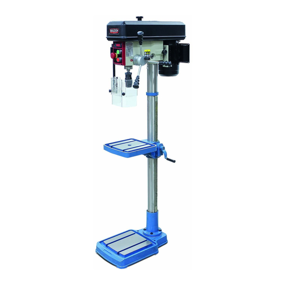
OPERATOR'S MANUAL
MULTI-SPEED BELT DRIVE DRILL PRESS
MODEL: DP-0625E
Baileigh Industrial, Inc.
P.O. Box 531
Manitowoc, WI 54221-0531
Phone: 920.684.4990
Fax: 920.684.3944
sales@baileigh.com
REPRODUCTION OF THIS MANUAL IN ANY FORM WITHOUT WRITTEN APPROVAL OF BAILEIGH INDUSTRIAL, INC.
IS PROHIBITED. Baileigh Industrial, Inc. does not assume and hereby disclaims any liability for any damage or loss
caused by an omission or error in this Operator's Manual, resulting from accident, negligence, or other occurrence.
Rev. 11/2018
© 2018 Baileigh Industrial, Inc.
Advertisement
Table of Contents

Related Manuals for Baileigh Industrial DP-0625E


Summary of Contents for Baileigh Industrial DP-0625E
- Page 1 REPRODUCTION OF THIS MANUAL IN ANY FORM WITHOUT WRITTEN APPROVAL OF BAILEIGH INDUSTRIAL, INC. IS PROHIBITED. Baileigh Industrial, Inc. does not assume and hereby disclaims any liability for any damage or loss caused by an omission or error in this Operator’s Manual, resulting from accident, negligence, or other occurrence.
-
Page 2: Table Of Contents
Table of Contents THANK YOU & WARRANTY ..................1 INTRODUCTION ......................3 GENERAL NOTES ......................3 SAFETY INSTRUCTIONS ....................4 SAFETY PRECAUTIONS ....................6 Dear Valued Customer: ....................6 TECHNICAL SPECIFICATIONS ..................9 TECHNICAL SUPPORT ....................10 UNPACKING AND CHECKING CONTENTS ..............10 Cleaning ........................ -
Page 3: Thank You & Warranty
THANK YOU & WARRANTY Thank you for your purchase of a machine from Baileigh Industrial. We hope that you find it productive and useful to you for a long time to come. Inspection & Acceptance. Buyer shall inspect all Goods within ten (10) days after receipt thereof. Buyer’s payment shall constitute final acceptance of the Goods and shall act as a waiver of the Buyer’s rights to inspect or... - Page 4 • A 30% re-stocking fee applies to all returns. Baileigh Industrial makes every effort to ensure that our posted specifications, images, pricing and product availability are as correct and timely as possible. We apologize for any discrepancies that may occur. Baileigh Industrial reserves the right to make any and all changes deemed necessary in the course of business including but not limited to pricing, product specifications, quantities, and product availability.
-
Page 5: Introduction
After receiving your equipment remove the protective container. Do a complete visual inspection, and if damage is noted, photograph it for insurance claims and contact your carrier at once, requesting inspection. Also contact Baileigh Industrial and inform them of the unexpected occurrence. Temporarily suspend installation. -
Page 6: Safety Instructions
IMPORTANT PLEASE READ THIS OPERATORS MANUAL CAREFULLY It contains important safety information, instructions, and necessary operating procedures. The continual observance of these procedures will help increase your production and extend the life of the equipment. SAFETY INSTRUCTIONS LEARN TO RECOGNIZE SAFETY INFORMATION This is the safety alert symbol. - Page 7 SAVE THESE INSTRUCTIONS. Refer to them often and use them to instruct others. PROTECT EYES Wear safety glasses or suitable eye protection when working on or around machinery. PROTECT AGAINST NOISE Prolonged exposure to loud noise can cause impairment or loss of hearing.
-
Page 8: Safety Precautions
TIP OVER HAZARD THIS MACHINE MUST BE ANCHORED TO THE FLOOR. To prevent possible tip over from unbalanced operation, properly anchor this machine to a suitable floor surface. If not familiar with such anchoring, consult a machinery rigging company trained and familiar with such installations and operations. - Page 9 3. Make sure guards are in place and in proper working order before operating machinery. 4. Remove any adjusting tools. Before operating the machine, make sure any adjusting tools have been removed. 5. Keep work area clean. Cluttered areas invite injuries. 6.
- Page 10 21. Keep children away. Children must never be allowed in the work area. DO NOT let them handle machines, tools, or extension cords. 22. Store idle equipment. When not in use, tools must be stored in a dry location to inhibit rust. Always lock up tools and keep them out of reach of children.
-
Page 11: Technical Specifications
TECHNICAL SPECIFICATIONS Drilling Capacity 0.625” (16mm) Chuck Keyless, B16, 0.039” – 0.625” (1 – 16mm) Spindle Travel 3.14” (80mm) Spindle Taper Quill Diameter 1.75” (45mm) Swing 14” (360mm) Min. Distance Spindle to Table 6” (152mm) Max. Distance Spindle to Table 35.43”... -
Page 12: Technical Support
TECHNICAL SUPPORT Our technical support department can be reached at 920.684.4990, and asking for the support desk for purchased machines. Tech Support handles questions on machine setup, schematics, warranty issues, and individual parts needs: (other than die sets and blades). For specific application needs or future machine purchases contact the Sales Department at: sales@baileigh.com, Phone: 920.684.4990, or Fax: 920.684.3944. -
Page 13: Transporting And Lifting
Your machine may be shipped with a rustproof waxy coating and/or grease on the exposed unpainted metal surfaces. Fully and completely remove this protective coating using a degreaser or solvent cleaner. Moving items will need to be moved along their travel path to allow for cleaning the entire surface. -
Page 14: Installation
• Level the machine so that all the supporting feet are taking the weight of the machine and no rocking is taking place. Follow these guidelines when lifting crane or hoist: • Always lift and carry the machine with the lifting holes provided at the top of the machine. •... -
Page 15: Anchoring The Machine
• WORKING CLEARANCES: Take into consideration the size of the material to be processed. Make sure that you allow enough space for you to operate the machine freely. • POWER SUPPLY PLACEMENT: The power supply should be located close enough to the machine so that the power cord is not in an area where it would cause a tripping hazard. -
Page 16: Getting To Know Your Machine
GETTING TO KNOW YOUR MACHINE... - Page 17 Item Description Base with work surface and T-slots. Work table with T-slots. Chuck Guard with safety interlock. Keyless Chuck. Operator Controls Removable Drive Cover. Provides access to the sheave to change the spindle speed. Drive Motor. Belt tension lock knobs. Two, one on each side. Head to Column Clamping Bolt.
-
Page 18: Assembly And Set Up
ASSEMBLY AND SET UP WARNING: For your own safety, DO NOT connect the machine to the power source until the machine is completely assembled and you read and understand the entire instruction manual. Note: A lifting device will be needed, and an assistant is highly recommended. 1. - Page 19 9. Position the headstock directly over the base by using a plumb bob and measuring tape or ruler across the drill press base to find its center. 10. Suspend the plumb line from the center of the headstock and lower the bob until it is near the tape/ruler as shown.
-
Page 20: Electrical
ELECTRICAL CAUTION: HAVE ELECTRICAL UTILITIES CONNECTED TO MACHINE BY A CERTIFIED ELECTRICIAN! Check if the available power supply is the same as listed on the machine nameplate. WARNING: Make sure the grounding wire (green) is properly connected to avoid electric shock. DO NOT switch the position of the green grounding wire if any electrical plug wires are switched during hookup. - Page 21 • Improper connection of the equipment-grounding conductor can result in risk of electric shock. The conductor with insulation having an outer surface that is green with or without yellow stripes is the equipment-grounding conductor. If repair or replacement of the electric cord or plug is necessary, do not connect the equipment-grounding conductor to a live terminal.
-
Page 22: Electrical Schematic
ELECTRICAL SCHEMATIC... -
Page 23: Operating Adjustments
OPERATING ADJUSTMENTS Belt / Speed Change 1. Disconnect the drill from the power supply. 2. Remove the lock knob and washer from the top of the belt cover. 3. Remove the belt cover 4. Use the chart on the face of the control panel to determine the rpm desired. -
Page 24: Depth Stop
Depth Stop This drill press comes with a depth stop adjustment for use when drilling. 1. Loosen the depth collar lock knob (A). 2. Secure the material you will be drilling onto the drill press table. 3. With the desired bit installed, lower the spindle until the tip of the bit just touches the material you will be drilling. -
Page 25: Drill Protection Guard
Drill Protection Guard The machine is provided with a security drill guard. Before pressing the starting push button, set the drill guard in the working position, otherwise the machine controls will not start. Important: If the guard is opened when operating the machine, the machine will stop. -
Page 26: Operating Precautions
OPERATING PRECAUTIONS The following operating and safety precautions must be observed in order to avoid harm to the operator or damage to the drill press. 1. Safety is the responsibility of the user/purchaser since conditions differ between jobs. Use and enforce safety procedures at each operation location and provide for any changes in conditions to provide maximum safety. -
Page 27: Indication Of Extreme Speeds And Feeds
9. Use the feed handle to feed the drill into the material. Use a smooth steady motion with enough force to allow the drill to cut. It may be necessary to raise the drill from time to time to allow the flutes to clear the material. 10. -
Page 28: Lubrication And Maintenance
LUBRICATION AND MAINTENANCE WARNING: Make sure the electrical disconnect is OFF before working on the machine. Maintenance should be performed on a regular basis by qualified personnel. Always follow proper safety precautions when working on or around any machinery. Daily Maintenance •... -
Page 29: Greasing The Machine
• Inspect regularly for tension and wear. Check pulleys to ensure that they are properly aligned. Note: Proper maintenance can increase the life expectancy of your machine. Greasing the Machine 1. Grease the gear rack on the column to keep the table moving smoothly. 7. - Page 30 Excessive feed rate for size of drill and material being drilled. Reduce feed pressure or use cutting fluid. No cutting fluid or improper Use correct cutting fluid. cutting fluid. Drill dull. Sharpen drill. Check that all T-slot hold-downs are tight, Lack of rigidity in hold-down and that table-lock and drill head bolts are method.
-
Page 31: Parts Diagram
PARTS DIAGRAM... -
Page 32: Parts List
Parts List Item Part No. Description S1601001 Base S1401015 Column support S1401010 Rack M12X40GB5783B Hex Cap Screw S1401003-02 Column M6X6GB80B Socket Set Screw S1401017 Retaining Ring S1401012 Lock Handle S1601009-01 Handle S1601008 Cone Gear Shaft S1601018 Pinion Shaft S1601020 Helical Gear S1401014-01 Table Φ45X4... - Page 33 Item Part No. Description BRG6203GB276 Bearing CLP40GB893D1B Spacer CLP17GB894D1B Rubber Washer S1402001 Headstock PIN4X16GB879D1B S1609009 Indicator M4X8GB818B Cross Pan Head Screw s14040020 Shaft S1604003 Scale Ring S1604013 Setting Ring S1604013 Bolt S1402005 Block S1604001 Handle seat S1604004 Locking Assembly S1604005 Handle Shift S1604011 Handle Ball...
- Page 34 Item Part No. Description M5X16GB818B Cross Pan Head Screw S1405002 Cover S1605010 Rubber Washer S1605013 Plate M5GB6170Z M5X12GB818B Cross Pan Head Screw BRG6005GB276 Bearing S1402023 Bearing Washer S1402022 Driving Sleeve S1605006-01 Spindle M24GB93B Spring Washer M24X1.5GB810B S1405001 Cover M4GB6170B WSH12GB96D1B Enlarged Washer S1605008 Handle...
- Page 35 Item Part No. Description M5X20GB823Z Cross Pan Head Screw S1409005 Block M8X20GB70D1B Hex Cap Screw M10X8GB77B Hex Socket Cap Screw Steel Ball SV-165-1C25 Micro Switch S1402004 Spacer NOTES...
- Page 36 , WI 54220 UFEK RIVE ANITOWOC : 920. 684. 4990 F : 920. 684. 3944 HONE www.baileigh.com BAILEIGH INDUSTRIAL, INC. 1455 S. C , CA 91761 AMPUS VENUE NTARIO : 920. 684. 4990 F : 920. 684. 3944 HONE BAILEIGH INDUSTRIAL LTD. U...
Need help?
Do you have a question about the DP-0625E and is the answer not in the manual?
Questions and answers