Table of Contents
Advertisement
Quick Links
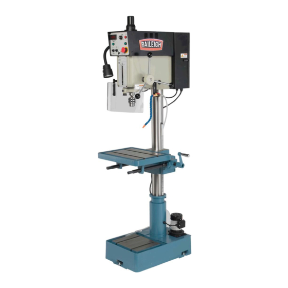
OPERATOR'S MANUAL
VARIABLE SPEED DRILL PRESS
REPRODUCTION OF THIS MANUAL IN ANY FORM WITHOUT WRITTEN APPROVAL OF BAILEIGH INDUSTRIAL
HOLDINGS LLC IS PROHIBITED. Baileigh Industrial Holdings LLC, Inc. does not assume and hereby disclaims any
liability for any damage or loss caused by an omission or error in this Operator's Manual, resulting from accident,
negligence, or other occurrence.
MODEL: DP-1000VS
Baileigh Industrial Holdings LLC
P.O. Box 531
Manitowoc, WI 54221-0531
Phone: 920.684.4990
Fax: 920.684.3944
sales@baileigh.com
© 2020 Baileigh Industrial Holdings LLC
Rev. 08/2020
Advertisement
Table of Contents

Related Manuals for Baileigh Industrial DP-1000VS


Summary of Contents for Baileigh Industrial DP-1000VS
- Page 1 REPRODUCTION OF THIS MANUAL IN ANY FORM WITHOUT WRITTEN APPROVAL OF BAILEIGH INDUSTRIAL HOLDINGS LLC IS PROHIBITED. Baileigh Industrial Holdings LLC, Inc. does not assume and hereby disclaims any liability for any damage or loss caused by an omission or error in this Operator’s Manual, resulting from accident, negligence, or other occurrence.
-
Page 2: Table Of Contents
Table of Contents THANK YOU & WARRANTY ..................1 INTRODUCTION ......................3 GENERAL NOTES ......................3 SAFETY INSTRUCTIONS ....................4 SAFETY PRECAUTIONS ....................7 Dear Valued Customer: ....................7 TECHNICAL SPECIFICATIONS ................... 10 TECHNICAL SUPPORT ....................11 UNPACKING AND CHECKING CONTENTS ..............12 TRANSPORTING AND LIFTING .................. - Page 3 CHUCK GUARD PART DIAGRAM ................45 Chuck Guard Parts List ..................... 46 ELECTRICAL SCHEMATIC ..................47 ELECTRICAL ENCLOSURE COMPONENTS .............. 48 Electrical Component Parts List ................. 49 TROUBLESHOOTING ....................50 TROUBLESHOOTING THE INVERTER ............... 52...
-
Page 4: Thank You & Warranty
THANK YOU & WARRANTY Thank you for your purchase of a machine from Baileigh Industrial Holdings LLC. We hope that you find it productive and useful to you for a long time to come. Inspection & Acceptance. Buyer shall inspect all Goods within ten (10) days after receipt thereof. Buyer’s payment shall constitute final acceptance of the Goods and shall act as a waiver of the Buyer’s rights to inspect or... - Page 5 We apologize for any discrepancies that may occur. Baileigh Industrial Holdings LLC reserves the right to make any and all changes deemed necessary in the course of business including but not limited to pricing, product specifications, quantities, and product availability.
-
Page 6: Introduction
INTRODUCTION The quality and reliability of the components assembled on a Baileigh Industrial Holdings LLC machine guarantee near perfect functioning, free from problems, even under the most demanding working conditions. However, if a situation arises, refer to the manual first. If a solution cannot be found, contact the distributor where you purchased our product. -
Page 7: Safety Instructions
IMPORTANT PLEASE READ THIS OPERATORS MANUAL CAREFULLY It contains important safety information, instructions, and necessary operating procedures. The continual observance of these procedures will help increase your production and extend the life of the equipment. SAFETY INSTRUCTIONS LEARN TO RECOGNIZE SAFETY INFORMATION This is the safety alert symbol. - Page 8 SAVE THESE INSTRUCTIONS. Refer to them often and use them to instruct others. PROTECT EYES Wear safety glasses or suitable eye protection when working on or around machinery. PROTECT AGAINST NOISE Prolonged exposure to loud noise can cause impairment or loss of hearing.
- Page 9 HIGH VOLTAGE USE CAUTION IN HIGH VOLTAGE AREAS. DO NOT assume the power to be off. FOLLOW PROPER LOCKOUT PROCEDURES. EMERGENCY STOP BUTTON In the event of incorrect operation or dangerous conditions, the machine can be stopped immediately by pressing the E-STOP button. Twist the emergency stop button clockwise (cw) to reset.
-
Page 10: Safety Precautions
SAFETY PRECAUTIONS Metal working can be dangerous if safe and proper operating procedures are not followed. As with all machinery, there are certain hazards involved with the operation of the product. Using the machine with respect and caution will considerably lessen the possibility of personal injury. However, if normal safety precautions are overlooked or ignored, personal injury to the operator may result. - Page 11 7. Dressing material edges. Always chamfer and deburr all sharp edges. 8. Do not force tool. Your machine will do a better and safer job if used as intended. DO NOT use inappropriate attachments in an attempt to exceed the machine’s rated capacity. 9.
- Page 12 24. Inspect power and control cables periodically. Replace if damaged or bare wires are exposed. Bare wiring can kill! DO NOT touch live electrical components or parts. 25. DO NOT bypass or defeat any safety interlock systems. Additional Safety Precautions •...
-
Page 13: Technical Specifications
TECHNICAL SPECIFICATIONS Motor and Electricals: Power Input Requirements 220V, 1Ph, 60hz Motor Type TEFC Induction 2HP (1.5kw), 220V, 3ph, 60hz, 6.6A, Motor Power 1720rpm Starting Amps 9.2A Running Amps (No Load) 1.7A Inverter M-Type Power Cable 14awg, 6 Ft Power Plug Not included Recommended Circuit and Fuse/Breaker Size 20A Sound Emission Without Load... -
Page 14: Technical Support
.625” [5/8”] (15.857mm) T-Slot Size T-Slot Centers 7.4375” (188.1mm) Table Weight Capacity 154lbs (70kg) Column Diameter 3.62" (92mm) Base: Base Size 23.5" x 15.82" (597 x 402mm) Base Working Surface 14-3/4 X 11-13/16 In. (375 X 300mm) T-Slot Number T-Slot Size 5/8 In. -
Page 15: Unpacking And Checking Contents
UNPACKING AND CHECKING CONTENTS Your Baileigh machine is shipped complete. Separate all parts from the packing material and check each item carefully. Make certain all items are accounted for before discarding any packing material. WARNING: SUFFOCATION HAZARD! Immediately discard any plastic bags and packing materials to eliminate choking and suffocation hazards to children and animals. -
Page 16: Transporting And Lifting
TRANSPORTING AND LIFTING NOTICE: Lifting and carrying operations should be carried out by skilled workers, such as a truck operator, crane operator, etc. If a crane is used to lift the machine, attach the lifting chain carefully, making sure the machine is well balanced. Follow these guidelines when lifting with truck or trolley: •... -
Page 17: Installation
• Use lift equipment such as straps, chains, capable of lifting 1.5 to 2 times the weight of the machine. • Take proper precautions for handling and lifting. • Check if the load is properly balanced by lifting it an inch or two. •... -
Page 18: Anchoring The Machine
• POWER SUPPLY PLACEMENT: The power supply should be located close enough to the machine so that the power cord is not in an area where it would cause a tripping hazard. Be sure to observe all electrical codes if installing new circuits and/or outlets. Anchoring the Machine •... -
Page 19: Overall Dimensions
OVERALL DIMENSIONS... -
Page 20: Getting To Know Your Machine
GETTING TO KNOW YOUR MACHINE... - Page 21 Motor Cover Contains the motor and drive components Electrical Enclosure Houses the electrical components Down - Feed Handle Controls up-down movement of the spindle Column Supports the table and head Gear Rack Engages the table for height adjustment Handle Table height adjustment at two locations Coolant Pump Pumps coolant to the chuck Base...
- Page 22 DIGITAL INDICATOR 150-3000RPM SPINDLE SPEED Coolant Pump Selector Switch Starts the coolant flow for cutting. Reverse Button Reverses the spindle rotation for tapping only. Digital Indicator Displays the rate of spindle rotation in RPM. Spindle Speed Knob Changes the speed of spindle rotation. Drilling / Tapping Selector Switch Selects the mode of operation: drilling or tapping.
-
Page 23: The Drill Head
The Drill Head The drill head attaches to the top of the column. It houses the motor, spindle, controls, and transfer mechanisms. Attached to it is the electrical enclosure, the protective guard, the work light, and the coolant valve with nozzle. The Work Table The sturdy work table can be positioned at varying heights and rotated 180°... -
Page 24: Electrical
ELECTRICAL CAUTION: HAVE ELECTRICAL UTILITIES CONNECTED TO MACHINE BY A CERTIFIED ELECTRICIAN! Check if the available power supply is the same as listed on the machine nameplate. WARNING: Make sure the grounding wire (green) is properly connected to avoid electric shock. DO NOT switch the position of the green grounding wire if any electrical plug wires are switched during hookup. - Page 25 • Improper connection of the equipment-grounding conductor can result in risk of electric shock. The conductor with insulation having an outer surface that is green with or without yellow stripes is the equipment-grounding conductor. If repair or replacement of the electric cord or plug is necessary, do not connect the equipment-grounding conductor to a live terminal.
-
Page 26: Set Up And Adjustments
SET UP AND ADJUSTMENTS Adjusting the Gear Rack Height CAUTION: Failure to lock the collar can result in personal injury or damage to the machine. 1. Raising the table to an adequate working height may require raising the column gear rack. 2. -
Page 27: Operation
OPERATION CAUTION: Always wear proper eye protection with side shields, safety footwear, and leather gloves to protect from burrs and sharp edges. When handling large heavy materials make sure they are properly supported. Drilling DIGITAL INDICATOR 1. Load and secure the piece part to the table. 2. -
Page 28: Tapping
Tapping 1. Load and secure the piece part to the table. 1. Secure tapping tool in the chuck. DIGITAL INDICATOR 2. Unlock the table, adjust to the desired height, and relock the table. 150-3000RPM SPINDLE SPEED 3. Adjust the safety guard up or down as needed. 4. -
Page 29: Drilling Recommendations
DRILLING RECOMMENDATIONS Drilling Speeds The speed of a drill is usually measured in terms of the rate at which the outer periphery of the tool moves in relation to the work being drilled. The common term for this is Surface Feet per Minute (SFM). - Page 30 Speeds for High Speed Steel Drills Material Speed (SFPM) Alloy Steel — 300 to 400 Brinell 20-30 Stainless Steel 30-40 Automotive Steel Forgings 40-50 Tool Steel, 1.2C 50-60 Steel, .4C to .5C 70-80 Mild Machinery Steel, .2C to .3C 80-110 Hard Chilled Cast Iron 30-40 Medium Hard Cast Iron...
-
Page 31: Lubrication And Maintenance
LUBRICATION AND MAINTENANCE WARNING: Make sure the electrical disconnect is OFF before working on the machine. Maintenance should be performed on a regular basis by qualified personnel. Always follow proper safety precautions when working on or around any machinery. Daily Maintenance •... -
Page 32: Spindle Return Spring Adjustment
Spindle Return Spring Adjustment The spindle return is preset by the manufacturer and should not need adjustment. If future attention is ever required, proceed as follows: 1. Do NOT remove spring cap. 2. Loosen screw (E) just enough to rotate spring cap (F) past pin (Inside case. -
Page 33: Timing Belt Replacement
Timing Belt Replacement This machine is designed with a timing pulley and belt to provide greater braking response and torsion strength. The timing belt should be replaced when the belt is worn or broken. 1. Lockout power to the machine. 2. -
Page 34: Drill Head Parts Diagram
DRILL HEAD PARTS DIAGRAM A8-3 A2-1 A21-1 A21-2 A3-1 A15-1 A21 A20-2 A19-3 A19-2... - Page 35 A8-2 A8-1 A6-4 A6-1 A5-1 A6-3 A6-2 A19-1 A33-1...
- Page 36 A9-1 A20-8 A9-2 A20-9 A20-6 A30-1 A17-1 A31-1 A17-2 A20-5 A20-4 A18-1 A20-7 A20-2...
-
Page 37: Drill Head Parts List
Drill Head Parts List Item Part No. Description Qty. DP1000VS-A1 Pulley Cover DP1000VS-A2 Plate Bracket DP1000VS-A3 Electric Control Box A3-1 DP1000VS-A3-1 Hex. Socket Cap Screw M6x12 DP1000VS-A4 Q1, Safety Door Switch DP1000VS-A5 Drive Pulley Set Screw 5/16”X3/8” A5-1 DP1000VS-A5-1 A6-1 DP1000VS-A6-1 Spindle Pulley #MT3 Hex. - Page 38 Item Part No. Description Qty. DP1000VS-A18 Handle Rod A18-1 DP1000VS-A18-1 Knob DP1000VS-A19 Right Lock Sleeve A19-1 DP1000VS-A19-1 Left Lock Sleeve A19-2 DP1000VS-A19-2 Lock Handle Hex Nut 1/2” A19-3 DP1000VS-A19-3 Spindle Assembly (A20-2 ⁓ A20-9) DP1000VS-A20 A20-2 DP1000VS-A20-2 Spindle Shaft #MT3 A20-4 DP1000VS-A20-4 Quill #MT3 A20-5 DP1000VS-A20-5...
-
Page 39: Base, Column And Table Parts Diagram
BASE, COLUMN AND TABLE PARTS DIAGRAM B10-1... - Page 40 B6-1 B5-1 B5-2 B8-1...
-
Page 41: Base, Column And Table Parts List
Base, Column and Table Parts List Item Part No. Description Qty. DP1000VS-B1 Table DP1000VS-B2 Column DP1000VS-B3 Rack DP1000VS-B4 Crank shaft B5-1 DP1000VS-B5-1 Gear bracket B5-2 DP1000VS-B5-2 Hex. socket cap screw M8x1.25 Hex. socket cap screw 1/4”x1-1/2” DP1000VS-B6 Hex. Nut 1/4” B6-1 DP1000VS-B6-1 DP1000VS-B8... - Page 42 TABLE GEAR PARTS DIAGRAM B5-14 B5-13 B5-15 B5-12 B5-16 B5-11 B5-17 B5-1 B5-2 B5-10 B5-9 B5-18 B5-8 B5-3 B5-7 B5-4 B5-6 B5-5...
- Page 43 Table Gear Parts List Item Part No. Description Qty. B5-1 DP1000VS-B5-1 Gear bracket B5-2 DP1000VS-B5-2 Hex. socket cap screw M8x35 B5-3 DP1000VS-B5-3 Key 5x5x30 B5-4 DP1000VS-B5-4 Shaft Gear/set screw 1/4”x 3/8” B5-5 DP1000VS-B5-5 Worm gear/set screw 1/4”x3/8” B5-6 DP1000VS-B5-6 B5-7 DP1000VS-B5-7 Worm shaft B5-8...
-
Page 44: Coolant Pump Assembly Parts Diagram
COOLANT PUMP ASSEMBLY PARTS DIAGRAM... -
Page 45: Coolant Pump Assembly Parts List
Coolant Pump Assembly Parts List Item Part No. Description DP1000VS-B15 Reservoir Cover DP1000VS-B16 M2, Coolant Pump B16-1 DP1000VS-B16-1 Hex Nut B16-2 DP1000VS-B16-2 Washer B16-3 DP1000VS-B16-3 Hex Cap Bolt B16-4 DP1000VS-B16-4 Cord B16-5 DP1000VS-B16-5 Hose Nipples B16-6 DP1000VS-B16-6 Worm Drive Hose Clamp B16-7 DP1000VS-B16-7 Discharge Tube/Hose... -
Page 46: Control Panel Parts Diagram
CONTROL PANEL PARTS DIAGRAM... -
Page 47: Control Panel Parts List
Control Panel Parts List Item Part No. Description DP1000VS-D1 Control Panel LD DP1000VS-D2 SB2, Stop Switch DP1000VS-D3 SB5, Reverse Switch DP1000VS-D4 Digital Readout Assembly DP1000VS-D5 VR, Speed Control Knob DP1000VS-D6 SB6, Pump Switch DP1000VS-D7 SB4, Drill / Tapping Switch DP1000VS-D8 SB3, Start Switch DP1000VS-D9 SB1, Emergency Stop Switch... -
Page 48: Chuck Guard Part Diagram
CHUCK GUARD PART DIAGRAM... -
Page 49: Chuck Guard Parts List
Chuck Guard Parts List Item Part No. Description Qty. DP15VSF-G1 Spring Pin, 3x16mm DP15VSF-G2 Support Bracket Bar DP15VSF-G3 Bushing DP15VSF-G4 Spacer DP15VSF-G5 Rachet Lock Handle M6x20 DP15VSF-G6 C-Clip S30 DP15VSF-G7 Bracket DP15VSF-G8 Safety Shield, Lexan 410x210mm DP15VSF-G9 Lower Bracket Bar DP15VSF-G10 Hex Socket Head Cap Screw M8x12 DP15VSF-G11... -
Page 50: Electrical Schematic
ELECTRICAL SCHEMATIC VFD-B 200W 220V... -
Page 51: Electrical Enclosure Components
ELECTRICAL ENCLOSURE COMPONENTS... -
Page 52: Electrical Component Parts List
Electrical Component Parts List Item Description Data Main Disconnect Switch 500VAC,16A,60Hz Fuses 500V~10 x 38, .5A Fuses 500V~10 x 38, .5A Fuses 500V~10 x 38, 3A Coil 24V, 50/60 Hz, Ui=660V, AC1=25A, AC# Contactor 220V, 2.2KW, 380V, 4.0KW, 4<<a>> Coil 24V, 50/60 Hz, Ui=660V, AC1=25A, AC# Contactor 220V, 2.2KW, 380V, 4.0KW, 4<<a>>... -
Page 53: Troubleshooting
TROUBLESHOOTING WARNING: Make sure the electrical disconnect is OFF before working on the machine. FAULT PROBABLE CAUSE REMEDY Wrong voltage Make sure the machine voltage matches the nameplate. Emergency switch has been pressed. Turn E-Stop switch clockwise (cw) to reset. Wait 10 sec. for the Delta motor Electrical enclosure door controller to reset. - Page 54 Noisy motor Check motor bearings or loose fan motor. Excessive speed. Reduce speed. Chips not clearing. Use pecking operation to clear chips. Drill or Tool Heats Dull tool. Sharpen tool or replace. up or Burns Work Feed rate too slow. Increase feed enough to clear chips.
-
Page 55: Troubleshooting The Inverter
TROUBLESHOOTING THE INVERTER Prior to operating or adjusting any electronic component, qualified personnel must take the following aspects into consideration: • Disconnect machine from the power supply. • DO NOT use bare hands or metal tools to remove or install sensitive electronic parts. •... - Page 56 BAILEIGH INDUSTRIAL HOLDINGS LLC 1625 D , WI 54220 UFEK RIVE ANITOWOC : 920. 684. 4990 F : 920. 684. 3944 HONE www.baileigh.com BAILEIGH INDUSTRIAL HOLDINGS LTD. U WIFT OINT WIFT ALLEY NDUSTRIAL STATE UGBY , CV21 1QH U IDLANDS...
Need help?
Do you have a question about the DP-1000VS and is the answer not in the manual?
Questions and answers