Table of Contents
Advertisement
OPERATOR'S MANUAL
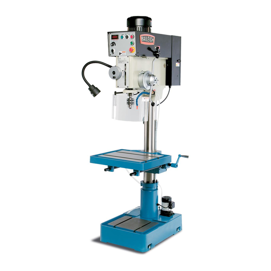
VARIABLE SPEED DRILL PRESS
REPRODUCTION OF THIS MANUAL IN ANY FORM WITHOUT WRITTEN APPROVAL OF BAILEIGH INDUSTRIAL
HOLDINGS LLC IS PROHIBITED. Baileigh Industrial Holdings LLC, Inc. does not assume and hereby disclaims any
liability for any damage or loss caused by an omission or error in this Operator's Manual, resulting from accident,
negligence, or other occurrence.
MODEL: DP-1500VS
Baileigh Industrial Holdings LLC
P.O. Box 531
Manitowoc, WI 54221-0531
Phone: 920.684.4990
Fax: 920.684.3944
sales@baileigh.com
© 2020 Baileigh Industrial Holdings LLC
Rev. 08/2020
Advertisement
Table of Contents

Subscribe to Our Youtube Channel
Related Manuals for Baileigh Industrial DP-1500VS


Summary of Contents for Baileigh Industrial DP-1500VS
- Page 1 REPRODUCTION OF THIS MANUAL IN ANY FORM WITHOUT WRITTEN APPROVAL OF BAILEIGH INDUSTRIAL HOLDINGS LLC IS PROHIBITED. Baileigh Industrial Holdings LLC, Inc. does not assume and hereby disclaims any liability for any damage or loss caused by an omission or error in this Operator’s Manual, resulting from accident, negligence, or other occurrence.
-
Page 2: Table Of Contents
Table of Contents THANK YOU & WARRANTY ..................1 INTRODUCTION ......................3 GENERAL NOTES ......................3 SAFETY INSTRUCTIONS ....................4 SAFETY PRECAUTIONS ....................7 Dear Valued Customer: ....................7 TECHNICAL SPECIFICATIONS ................... 10 TECHNICAL SUPPORT ....................11 UNPACKING AND CHECKING CONTENTS ..............12 TRANSPORTING AND LIFTING .................. - Page 3 Parts List C – Column/Table/Base ................47 PARTS IDENTIFICATION DRAWING D ............... 49 Parts List D – Electrical Control Panel ............... 50 PARTS IDENTIFICATION DRAWING E ............... 51 Parts List E – Electrical Enclosure ................52 CHUCK GUARD PART DIAGRAM ................53 Chuck Guard Parts List .....................
-
Page 4: Thank You & Warranty
THANK YOU & WARRANTY Thank you for your purchase of a machine from Baileigh Industrial Holdings LLC. We hope that you find it productive and useful to you for a long time to come. Inspection & Acceptance. Buyer shall inspect all Goods within ten (10) days after receipt thereof. Buyer’s payment shall constitute final acceptance of the Goods and shall act as a waiver of the Buyer’s rights to inspect or... - Page 5 We apologize for any discrepancies that may occur. Baileigh Industrial Holdings LLC reserves the right to make any and all changes deemed necessary in the course of business including but not limited to pricing, product specifications, quantities, and product availability.
-
Page 6: Introduction
INTRODUCTION The quality and reliability of the components assembled on a Baileigh Industrial Holdings LLC machine guarantee near perfect functioning, free from problems, even under the most demanding working conditions. However, if a situation arises, refer to the manual first. If a solution cannot be found, contact the distributor where you purchased our product. -
Page 7: Safety Instructions
IMPORTANT PLEASE READ THIS OPERATORS MANUAL CAREFULLY It contains important safety information, instructions, and necessary operating procedures. The continual observance of these procedures will help increase your production and extend the life of the equipment. SAFETY INSTRUCTIONS LEARN TO RECOGNIZE SAFETY INFORMATION This is the safety alert symbol. - Page 8 SAVE THESE INSTRUCTIONS. Refer to them often and use them to instruct others. PROTECT EYES Wear safety glasses or suitable eye protection when working on or around machinery. PROTECT AGAINST NOISE Prolonged exposure to loud noise can cause impairment or loss of hearing.
- Page 9 ENTANGLEMENT HAZARD – ROTATING SPINDLE Contain long hair, DO NOT wear jewelry or loose fitting clothing. EMERGENCY STOP BUTTON In the event of incorrect operation or dangerous conditions, the machine can be stopped immediately by pressing the E-STOP button. Twist the emergency stop button clockwise (cw) to reset. Note: Resetting the E-Stop will not start the machine.
-
Page 10: Safety Precautions
SAFETY PRECAUTIONS Metal working can be dangerous if safe and proper operating procedures are not followed. As with all machinery, there are certain hazards involved with the operation of the product. Using the machine with respect and caution will considerably lessen the possibility of personal injury. However, if normal safety precautions are overlooked or ignored, personal injury to the operator may result. - Page 11 8. Do not force tool. Your machine will do a better and safer job if used as intended. DO NOT use inappropriate attachments in an attempt to exceed the machine’s rated capacity. 9. Use the right tool for the job. DO NOT attempt to force a small tool or attachment to do the work of a large industrial tool.
- Page 12 Additional Safety Precautions • Turn off main power to the machine and wait for the drill bit, or cutting tool to stop turning before removing debris, removing or securing the piece part, or changing the position of the work table. •...
-
Page 13: Technical Specifications
TECHNICAL SPECIFICATIONS Motor and Electricals: Power Input Requirements 220V, 1Ph, 60hz Motor Type TEFC Induction Motor Power 2HP (1.5kw), 220V, 3ph, 60hz, 10A, 1720rpm Inverter M-Type Power Cable 14awg, 6 Ft Power Plug Not included Recommended Circuit and Fuse/Breaker Size 20A Sound Emission Without Load 70db Coolant Pump... -
Page 14: Technical Support
.625” [5/8”] (15.857mm) T-Slot Size T-Slot Centers 7.4375” (188.1mm) Table Weight Capacity 154lbs (70kg) Column Diameter 4.52" (115mm) Base: Base Size 27" x 19" (686 x 483mm) Base Working Surface 14-3/4 X 11-13/16 In. (375 X 300mm) T-Slot Number .625” [5/8”] (15.857mm) T-Slot Size Main Materials: Head... -
Page 15: Unpacking And Checking Contents
UNPACKING AND CHECKING CONTENTS Your Baileigh machine is shipped complete. Separate all parts from the packing material and check each item carefully. Make certain all items are accounted for before discarding any packing material. WARNING: SUFFOCATION HAZARD! Immediately discard any plastic bags and packing materials to eliminate choking and suffocation hazards to children and animals. -
Page 16: Transporting And Lifting
TRANSPORTING AND LIFTING NOTICE: Lifting and carrying operations should be carried out by skilled workers, such as a truck operator, crane operator, etc. If a crane is used to lift the machine, attach the lifting chain carefully, making sure the machine is well balanced. Follow these guidelines when lifting with truck or trolley: •... -
Page 17: Installation
• Use lift equipment such as straps, chains, capable of lifting 1.5 to 2 times the weight of the machine. • Take proper precautions for handling and lifting. • Check if the load is properly balanced by lifting it an inch or two. •... -
Page 18: Anchoring The Machine
• POWER SUPPLY PLACEMENT: The power supply should be located close enough to the machine so that the power cord is not in an area where it would cause a tripping hazard. Be sure to observe all electrical codes if installing new circuits and/or outlets. Anchoring the Machine •... -
Page 19: Getting To Know Your Machine
GETTING TO KNOW YOUR MACHINE... - Page 20 Motor Provides power to the chuck Changes spindle speed RPM. DO NOT change spindle 2-Speed Hi-Lo RPM until the spindle has stopped completely Electrical Enclosure Houses the electrical components View Port Used to see that the rear worm shaft has grease Down-Feed Handle Changes down-feed from Auto to Manual Column...
- Page 21 Oil Level Gauge Shows current level of gear oil Limit Switch Stops machine when guard is swung away Grease Fitting Use to grease the rear worm shaft Guard Knob Use to hold guard after pivoting sideways Automatic Down Feed Select from 3 speeds for automatic down feed Guard Adjustment Knob Change guard height and lock with knob DIGITAL INDICATOR...
- Page 22 High / Low Gear Selector A gear transmission lever that selects Hi or Low speeds. IMPORTANT: Use only while the machine is stopped. Failure to do so will cause damage to the gear system. Drill Head The Drill Head attaches to the top of the column. It houses the motor, spindle, controls, and transfer mechanisms.
-
Page 23: Electrical
ELECTRICAL CAUTION: HAVE ELECTRICAL UTILITIES CONNECTED TO MACHINE BY A CERTIFIED ELECTRICIAN! Check if the available power supply is the same as listed on the machine nameplate. WARNING: Make sure the grounding wire (green) is properly connected to avoid electric shock. DO NOT switch the position of the green grounding wire if any electrical plug wires are switched during hookup. - Page 24 • Improper connection of the equipment-grounding conductor can result in risk of electric shock. The conductor with insulation having an outer surface that is green with or without yellow stripes is the equipment-grounding conductor. If repair or replacement of the electric cord or plug is necessary, do not connect the equipment-grounding conductor to a live terminal.
-
Page 25: Operation Setup And Description
OPERATION SETUP AND DESCRIPTION CAUTION: Always wear proper eye protection with side shields, safety footwear, and leather gloves to protect from burrs and sharp edges. Changing the Spindle Speed 1. Change speed ranges with the Hi/Low gear selector lever (B). IMPORTANT: Use only while the machine is stopped. -
Page 26: Setting The Depth Stop
Setting the Depth Stop This machine has some built-in control stops that activate when either the front depth scale or side depth scale ring reaches zero. Their functions include stop drilling, reverse tapping, or return the drill bit to the start height. 1. -
Page 27: Manual Down-Feed
Manual Down-feed The down-feed rate changes can only be made while the motor is running and the selector switch (AE) is set to drilling mode. DIGITAL INDICATOR 245-2000 65-540 1. Start machine by pressing start button (AG). 2. Set the down-feed rate to “0” using handle (X). 3. -
Page 28: Micro-Feed Hand Wheel
Note: If the bit has difficulty drilling or the spindle Remove bounces during the drilling process, stop drilling immediately. Check to see that the drill bit is sharp and that the material is not too hard. When the machine is used for heavy drilling over a long period of time, it is recommended to check the loading capacity of automatic quill feeding on a regular basis. -
Page 29: Operation
OPERATION CAUTION: Always wear proper eye protection with side shields, safety footwear, and leather gloves to protect from burrs and sharp edges. 1. Check that the head is secure to the column. 2. Secure the piece part to the table. 3. -
Page 30: Tapping Mode
Tapping Mode In general, speeds for tapping require low transmission mode with speeds lower than 150 RPM. Note: All tapping must be done while in manual mode. 1. Set the down-feed rate to “0” using the down-feed handle (X). Refer to manual down-feed. 2. -
Page 31: Drilling Recommendations
DRILLING RECOMMENDATIONS Drilling Speeds The speed of a drill is usually measured in terms of the rate at which the outer periphery of the tool moves in relation to the work being drilled. The common term for this is Surface Feet per Minute (SFM). - Page 32 Speeds for High Speed Steel Drills Material Speed (SFPM) Alloy Steel — 300 to 400 Brinell 20-30 Stainless Steel 30-40 Automotive Steel Forgings 40-50 Tool Steel, 1.2C 50-60 Steel, .4C to .5C 70-80 Mild Machinery Steel, .2C to .3C 80-110 Hard Chilled Cast Iron 30-40 Medium Hard Cast Iron...
-
Page 33: Lubrication And Maintenance
LUBRICATION AND MAINTENANCE WARNING: Make sure the electrical disconnect is OFF before working on the machine. Maintenance should be performed on a regular basis by qualified personnel. Always follow proper safety precautions when working on or around any machinery. Daily Maintenance •... -
Page 34: Return Spring
If an adjustment becomes necessary, please contact a service representative at Baileigh Industrial. Ph: (920-684-4990) The figure at right shows the spring cap which houses the spring. Replacing Gearbox Oil •... -
Page 35: Greasing The Machine
Greasing the Machine 1. Keep gear shaft lubricated with grease fitting (V). (View the shaft through the portal on the opposite side of the drill head). 2. Grease the gear rack on the column to keep the table moving smoothly. 3. -
Page 36: Motor / Drive Belt Replacement
Motor / Drive Belt Replacement 1. Disconnect machine from power source. Disconnect electrical power to drill press to avoid possibility of inadvertent operation and exposure to potentially lethal voltage levels. Note: Prefer to the parts diagram as needed to aid in disassembly and assembly. 2. -
Page 37: Parts Identification Drawing A
PARTS IDENTIFICATION DRAWING A... -
Page 39: Parts List A - Head/Spindle Assembly
Parts List A – Head/Spindle Assembly Item Part No. Description Qty. A-01 DP1500VS-A-01 Flat Head Screw M6x16 A-02 DP1500VS-A-02 Cover A-03 DP1500VS-A-03 Feed Clutch Rod A-04 DP1500VS-A-04 A-05 DP1500VS-A-05 Roll Pin A-06 DP1500VS-A-06 Set Screw M5x6 A-07 DP1500VS-A-07 Grip A-08 DP1500VS-A-08 Feed Handle A-09... - Page 40 Item Part No. Description Qty. A-33 DP1500VS-A-33 Screw Bushing A-34 DP1500VS-A-34 Sleeve A-35 DP1500VS-A-35 Ball Bearing 6004ZZ A-37 DP1500VS-A-37 Key 5x15 A-38 DP1500VS-A-38 Worm Shaft Support A-39 DP1500VS-A-39 Set Screw M6x12 A-40 DP1500VS-A-40 Screw M5x6 A-42 DP1500VS-A-42 Set Knob A-46 DP1500VS-A-46 Hex Socket Cap Screw M6x16 A-47...
- Page 41 Item Part No. Description Qty. A-73 DP1500VS-A-73 Guide Plate A-74 DP1500VS-A-74 Spring A-75 DP1500VS-A-75 Jaw Clutch A-76 DP1500VS-A-76 Special Spring A-77 DP1500VS-A-77 Jaw Clutch Cover A-78 DP1500VS-A-78 Flat Head Screw M6x16 A-79 DP1500VS-A-79 Adjustable Screw A-80 DP1500VS-A-80 Ball Bearing 6305ZZ A-81 DP1500VS-A-81 Feed Cover...
- Page 42 Item Part No. Description Qty. A-110 DP1500VS-A-110 C-Clip R-35 A-111 DP1500VS-A-111 Cover Plate A-112 DP1500VS-A-112 Spring Washer M6 A-113 DP1500VS-A-113 Hex Socket Cap Screw M6x16 A-114 DP1500VS-A-114 Hex Nut M20 A-115 DP1500VS-A-115 Spacer A-116 DP1500VS-A-116 Belleville Spring Washer A-117 DP1500VS-A-117 Worm A-118 DP1500VS-A-118...
- Page 43 Item Part No. Description Qty. A-165 DP1500VS-A-165 Micro Switch Support Rod A-166 DP1500VS-A-166 QS2, QS3, Micro Switch A-167 DP1500VS-A-167 Cross Head Screw M3x16 Set Screw 1/4”x1/4” A-168 DP1500VS-A-168 A-176 DP1500VS-A-176 A-177 DP1500VS-A-177 Hand wheel Handle A-178 DP1500VS-A-178 Pin Hole Plate A-179 DP1500VS-A-179 Pointer...
-
Page 44: Parts Identification Drawing B
PARTS IDENTIFICATION DRAWING B... -
Page 46: Parts List B - Motor/Pulley Assembly
Parts List B – Motor/pulley Assembly Item Part No. Description Qty. B-01 DP1500VS-B-01 Hex Hand Plugs 3/8" B-02 DP1500VS-B-02 Sight Glass B-03 DP1500VS-B-03 Ball Bearing 6202ZZ B-04 DP1500VS-B-04 C-Clip S-31 B-05 DP1500VS-B-05 Gear M=2, T=32 B-06 DP1500VS-B-06 Key 6x20mm B-07 DP1500VS-B-07 Drive Shaft M=2, T=13 B-08... - Page 47 Item Part No. Description Qty. B-34 DP1500VS-B-34 Set Screw M6x8 B-35 DP1500VS-B-35 Hex Socket Cap Screw M8x35 B-36 DP1500VS-B-36 Oil Seal 25x5mm B-37 DP1500VS-B-37 Taper Pin 5x38mm B-38 DP1500VS-B-38 Gear Box B-39 DP1500VS-B-39 Oil Filter 3/8"x3/8" B-40 DP1500VS-B-40 Tube B-41 DP1500VS-B-41 Oil Seal 62x35x10mm B-42...
- Page 48 Item Part No. Description Qty. B-67 DP1500VS-B-67 Spring Washer M8 B-68 DP1500VS-B-68 Spindle Speed Sensor B-69 DP1500VS-B-69 Sensor Support B-70 DP1500VS-B-70 Sensor Bracket B-71 DP1500VS-B-71 Screw M4x20 B-72 DP1500VS-B-72 Screw M4x6 B-73 DP1500VS-B-73 Hex Socket Cap Screw M5x10 B-74 DP1500VS-B-74 Hex Socket Cap Screw 3/16"x3/4"...
-
Page 49: Parts Identification Drawing C
PARTS IDENTIFICATION DRAWING C... -
Page 50: Parts List C - Column/Table/Base
Parts List C – Column/Table/Base Item Part No. Description Qty. C-01 DP1500VS-C-01 Coolant Base C-02 DP1500VS-C-02 Spring Pin 4x50m C-03 DP1500VS-C-03 Hex Head Plugs 3/8" C-04 DP1500VS-C-04 Set Screw 1/2"x1" C-05 DP1500VS-C-05 Cable Relief C-06 DP1500VS-C-06 Column C-07 DP1500VS-C-07 Brass Block 3/8" C-08 DP1500VS-C-08 Set Screw 3/8"x5/1 6"... - Page 51 Item Part No. Description Qty. C-34 DP1500VS-C-34 Crank Shaft C-35 DP1500VS-C-35 Ball Bearing 6005Z C-36 DP1500VS-C-36 Bevel Gear C-37 DP1500VS-C-37 Set Screw 1/4"x3/8" C-38 DP1500VS-C-38 Gear Bracket C-39 DP1500VS-C-39 Small Bevel Gear C-40 DP1500VS-C-40 Flange C-41 DP1500VS-C-41 Spring Washer M6 C-42 DP1500VS-C-42 Hex Socket Cap Screw M6x25...
-
Page 52: Parts Identification Drawing D
PARTS IDENTIFICATION DRAWING D... -
Page 53: Parts List D - Electrical Control Panel
Parts List D – Electrical Control Panel Item Part No. Description Qty. D-01 DP1500VS-D-01 SB3, Start Switch D-02 DP1500VS-D-02 SB2, Stop Switch D-03 DP1500VS-D-03 SB1, Emergency Stop Switch D-05 DP1500VS-D-05 SB6, Coolant Pump Switch D-06 DP1500VS-D-06 VR, Speed Control w/Knob D-07 DP1500VS-D-07 Speed Controller Display (DRO) -
Page 54: Parts Identification Drawing E
PARTS IDENTIFICATION DRAWING E... -
Page 55: Parts List E - Electrical Enclosure
Parts List E – Electrical Enclosure Item Part No. Description Qty. E-01 DP1500VS-E-01 Electric Control Box w/Door and Latch E-02 DP1500VS-E-02 Plastic Plate E-03 DP1500VS-E-03 Screw M4x6 E-04 DP1500VS-E-04 Cover E-05 DP1500VS-E-05 Electric Base Plate E-06 DP1500VS-E-06 Cable Relief E-07 DP1500VS-E-07 Washer M8 E-08... -
Page 56: Chuck Guard Part Diagram
CHUCK GUARD PART DIAGRAM... -
Page 57: Chuck Guard Parts List
Chuck Guard Parts List Item Part No. Description Qty. DP15VSF-G1 Spring Pin, 3x16mm DP15VSF-G2 Support Bracket Bar DP15VSF-G3 Bushing DP15VSF-G4 Spacer DP15VSF-G5 Rachet Lock Handle M6x20 DP15VSF-G6 C-Clip S30 DP15VSF-G7 Bracket DP15VSF-G8 Safety Shield, Lexan 410x210mm DP15VSF-G9 Lower Bracket Bar DP15VSF-G10 Hex Socket Head Cap Screw M8x12 DP15VSF-G11... -
Page 58: Electrical Schematic
ELECTRICAL SCHEMATIC VFD-B 200W 220V... -
Page 59: Electrical Enclosure Components
ELECTRICAL ENCLOSURE COMPONENTS... -
Page 60: Electrical Component Parts List
Electrical Component Parts List Item Description Data Main Disconnect Switch 500VAC,16A,60Hz Fuses 500V~10 x 38, 0.5A Fuses 500V~10 x 38, 0.5A Fuses 500V~10 x 38, 3A Coil 24V, 50/60 Hz, Ui=660V, AC1=25A, AC# Contactor 220V, 2.2KW, 380V, 4.0KW, 4<<a>> Coil 24V, 50/60 Hz, Ui=660V, AC1=25A, AC# Contactor 220V, 2.2KW, 380V, 4.0KW, 4<<a>>... -
Page 61: Troubleshooting
TROUBLESHOOTING WARNING: Make sure the electrical disconnect is OFF before working on the machine. FAULT PROBABLE CAUSE REMEDY 1. Wrong voltage 1. Make sure the machine voltage matches the nameplate. 2. Emergency switch has been 2. Turn E-Stop switch clockwise (cw) pressed. -
Page 62: Troubleshooting The Inverter
FAULT PROBABLE CAUSE REMEDY 1. Excessive speed. 1. Reduce speed. 2. Chips not clearing. 2. Use pecking operation to clear chips. Drill or Tool Heats 3. Dull tool. 3. Sharpen tool or replace. up or Burns Work 4. Feed rate too slow. 4. - Page 63 * When the display continues to show the same code, contact Baileigh Industrial at (920)684-4990 * Internal EEPROM can not be read or programmed. C.F1~3 or others * Current sensor error. * Return to Baileigh Industrial. * U-phase error. * W-phase error...
- Page 64 BAILEIGH INDUSTRIAL HOLDINGS LLC 1625 D , WI 54220 UFEK RIVE ANITOWOC : 920. 684. 4990 F : 920. 684. 3944 HONE www.baileigh.com BAILEIGH INDUSTRIAL HOLDINGS LTD. U WIFT OINT WIFT ALLEY NDUSTRIAL STATE UGBY , CV21 1QH U IDLANDS...
Need help?
Do you have a question about the DP-1500VS and is the answer not in the manual?
Questions and answers